By Urban Rudez, Rajne Ilievska, Denis Sodin, Janez Zakonjsek, Rafael Mihalic, Slovenia
Acknowledgements: This work was funded by the Slovenian Research Agency through the research program Electric Power Systems No. P2-0356 and project Resource management for low latency reliable communications in smart grids-LoLaG, J2-9232. Furthermore, this work was supported by European Regional Development Fund through the OIS-AIR project with the financial support of the ADRION program. We gratefully acknowledge Relematika Ltd. for their efforts in the algorithm implementation and the donation of TOR 300 IED. This work is a subject to a pending International Patent Application No. PCT/EP2018/059048 filled on April 9, 2018.
The power-engineering community uses the term frequency with great ease and with high confidence. This is probably a result of frequency efficiently driving both the control and protection mechanisms of power-systems for decades. However, when it comes to its first time derivative RoCoF (Rate-of-Change-of-Frequency), the attitude of engineers is much more cautious, despite RoCoF being already widely present in individual machine protection installations.
There are only a handful of attempts, in which modernization of under-frequency load shedding (UFLS) includes ANSI 81R relays (ANSI numbers identify the functions of medium voltage microprocessor devices, where 81R refers to a ROCOF function). In fact, system operators show strong reservations about more sophisticated use of RoCoF for emergency active-power balancing.
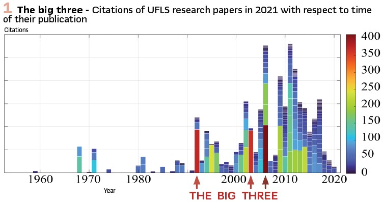
At first glance, the reasons for such an attitude seem understandable. Electrical-voltage frequency measurements are known for their high noise rate, which is significantly intensified when a time derivative is performed. In order to distillate usable RoCoF values, measuring windows of several cycles are required. This appears to be a main obstacle since power systems are facing new challenges invoked by decreased amounts of inertial masses. Not only that frequency changes faster in low-inertia systems, such systems are also more sensitive to power changes. System operators are obviously determined to adapt to fast frequency changes by improving the speed of interventions and ignoring the need for accuracy of interventions. It is interesting to notice that the research community also shows a similar inclination, which can be confirmed by Figure 1. The diagram shows the citation quantity (as available in 2021) of UFLS research papers, published from 1960 to 2020. Of the approximately 400 considered papers, only three red-colored ones stand out and all three of them focus on speeding up the UFLS process by utilizing RoCoF. The “big three” strongly influence the majority of the remaining papers that more or less offer a variation of the original concept with some marginal improvements. Thus, they form some kind of a mainstream line of thoughts. It is therefore not surprising that outlier papers with less-known ideas have a hard time penetrating the minds of system-operator decision makers.
To break this knot, one of such outlier ideas is presented in this article, and its concept is proved by means of hardware-in-the-loop testing. The authors claim that by continuously monitoring RoCoF, frequency relays can be equipped with a very effective situational-awareness feature that contributes to a more accurate UFLS as a whole. Even though the concept can be applied to different frequency-control mechanisms of modern power systems, we will demonstrate a special use case in which a RoCoF-based function can operate alongside the conventional frequency-driven UFLS criterion and together form a fast and accurate power-balancing system-integrity protection. It might just be what both RoCoF and system operators have been waiting for.
Power-system frequency and emergency consumption tripping
The entire fuss related to the power-system frequency control and protection revolves around the need to maintain mechanical rotational speed of turbines (mostly gas and steam), driving synchronous machines, within quite narrow limits. At the moment, synchronous machines are still generating most of the electrical energy around the world and it is not unreasonable to expect that the transition towards 100% environmentally friendly and sustainable electricity generation will take its share of time. Since a significant share of the future power generation is expected to be distributed, UFLS will also need to be redesigned to intervene at low-voltage instead on medium-voltage level. Some even argue that UFLS will eventually be replaced by fast-frequency response of converter-interfaced generation (CIG). While this may be so, the entire transformation of the existing frequency control and protection concepts will not be sudden. It is a fact that in electric power systems, changes are not implemented in the course of a couple of days. In the meantime, conventional and new technologies/solutions will have to coexist, meaning that the frequency control and protection will remain an important aspect of power-system operation for quite some time.
Angular rotational speed of turbines/generators m (fm =2π m) is a physical quantity and therefore very tangible. Similar as in vehicles, fm at a certain point in time (instantaneous speed) can be determined and quite accurately and promptly measured. For protection and control mechanisms outside power plants on the other hand, fm is not easily accessible. Therefore, at best fm can be observed indirectly by estimating the frequency of the electrical voltage fe at a given network location. Under steady-state conditions, the two are the same. On the other hand, it is impossible to obtain the exact one-to-one transformation between fe and fm during the dynamic events.

By the definition in the broadest sense of the word, the term frequency indicates the number of occurrences/cycles N of a repeating event per unit time ∆T. However, by such definition the term instantaneous frequency does not make any sense as the cycle cannot be completed in an instant. This makes it different from the instantaneous speed, since we cannot calculate the frequency by making ∆T infinitesimally small (∆T is limited downwards to at least 1 full cycle). Considering this, there is no guarantee that the observed process is uniform. In fact, this is exactly what happens in electric power systems when power imbalances occur.
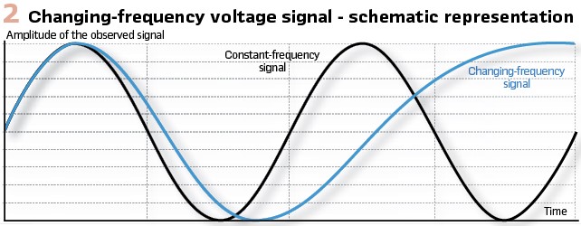
We are no longer dealing with a constant-frequency voltage signal, but rather with a changing-frequency voltage signal as schematically depicted in Figure2. When dealing with the latter, we can at best determine the average frequency over a time interval. This means that speaking of frequency in electric power systems is a bit tricky, since the concept of frequency can be defined only for ideal harmonic signals. For other signals we should use terms like average frequency and average frequency estimation.
In conventional power systems, the speed of synchronous machines does not change extremely fast. This means that ignoring the above distinction has not caused significant errors in frequency-driven control and protection. In CIG-dominated power systems however, this is no longer the case. Therefore, both the frequency as well as RoCoF demand wider measuring time windows. In any case, we should eliminate the term accurate RoCoF measurement from our vocabulary.
For decades, most of power systems around the world have used conventional emergency consumption tripping (UFLS) to stabilize the frequency when frequency control fails to do so in timely manner. Conventional UFLS is a system-integrity protection scheme that involves numerous frequency relays installed in most medium-voltage substations. Relays are tripped once they detect that the estimated fe falls below the static frequency setting. To handle various power imbalances, UFLS is equipped with several frequency settings (called static stages), each of which disconnects predefined group of medium-voltage feeders from the grid as soon as it is exceeded.
As the proportion of distributed generation increases, it becomes increasingly difficult to rely on the pre-defined decrease of system loading in each static stages. A solution to this problem is summarized in the next section.
Frequency-stability Margin
Microprocessor-based relays, referred to in this article as Intelligent Electronic Devices (IEDs), are capable of running different frequency-estimation fe algorithms (intellectual property of different vendors) and the purely mathematical calculation of its time derivative RoCoF (Figure 3). Due to high noise level in these signals, authors suggest to apply the moving-average and Median filtering as indicated by grey-coloured blocks in Figure 3. This suffices for supporting the algorithm, presented in the continuation.
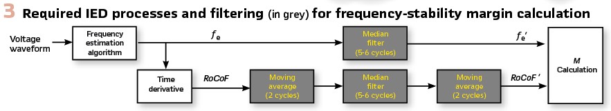
Once IED input signals are appropriately filtered, fe’ and RoCoF’ can jointly offer a better insight into power-system conditions as would fe by itself. Our research has shown that one of a very effective outcomes of combining these two time-dependent variables is a continuous yet still very simple estimation of the remaining time M (standing for frequency stability margin) before a violation of an arbitrary frequency limit fLIM is expected in a worst-case scenario. By the worst-case scenario we mean that both the frequency control and protection fail to do their task and consequently, unaltered frequency-decrease rate is expected. We depicted this graphically in the left-hand side of Figure 4, in which at time t = t1 a forecast of M is performed for two different power-imbalance cases (we used a yellow colour for ∆P1 and blue colour for ∆P2). We should note that under stabile (steady state) conditions, M value is infinite in theory.
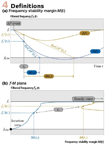
Our research has shown that the information carried by M can be efficiently exploited in the locus diagram (frequency fe’ versus frequency-stability margin M), the so-called f–M plane (provided in right-hand side of Figure 4). One can observe a very clear distinction between a yellow and blue case. After power imbalance occurs, locus point begins to follow a trajectory, starting on the far right-hand-side of the diagram and at fe’ = fr (rated system frequency). If frequency stabilizes without violating fLIM (yellow curve), trajectory is soon diverted back towards high M values (i.e. to the right). If this is not the case (blue curve), the trajectory continues to point towards the left-bottom part of the diagram (fe’ = fLIM and M = 0 to be precise, called location zero). It is important to remember that the location of a point in f–M plane corresponds to frequency prediction (see left-hand-side of Figure 4).
The strategy we developed was to surround the location zero with multiple load-shedding stages, forming UFLS zones. This is similar to a well-known distance protection concept with distance-protection zones. By doing this, static UFLS frequency thresholds fthr are replaced by M-dependent thresholds fthr(M). Even though infinite number of fthr(M) functions/strategies are possible, we will focus on the simplest (L-shaped) one in this article for the sake of clarity.
Use Case
The efficiency of a new type of UFLS thresholds setting was verified on two types of models:
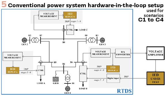
i) A conventional power system model (Figure 5) and
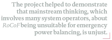
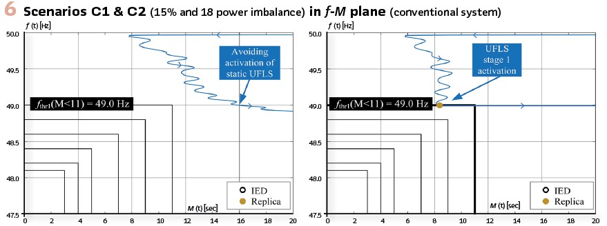
ii) A microgrid model (Figure8) For the conventional model, IEEE 9-bus system was used, whereas for microgrid model we adopted a library model of the used real-time digital simulator (RTDS) from RTDS Technologies Inc., Canada. In both cases, we simulated islanding event under different power-imbalance conditions by switching off the grid element. This caused the frequency to drop to such an extent that UFLS had to intervene. The implemented UFLS strategy followed these settings: fthr1(M < 11s) = 49.0 Hz (10% load decrease), fthr2(M < 9s) = 48.8 Hz (10% load decrease), fthr3(M < 7s) = 48.6 Hz (10% load decrease), fthr4(M < 5s) = 48.4 Hz (10% load decrease), fthr5(M < 4s) = 48.2 Hz (10% load decrease) and fthr6(M < 3s) = 48.1 Hz (5% load decrease). A graphical representation of these settings in f–M plane can be seen in any of Figures 6, 7, 9 or 10.
Initially, UFLS strategy was implemented on a protection relay, i.e. a TOR 300 series IED. However, since UFLS is a system-wide scheme involving numerous relays and we had only one available, we had to create a digital replica of UFLS functionalities, performed by the IED. In this way we were able to perform load control (grey shaded areas in Figure 5 and Figure 8) in more than one substation, where a single substation was controlled by the physical IED and the remaining substation by the replicas. This can be seen in Figure 5 and Figure 8 where the boundaries of the RTDS computer model are marked by a blue rectangle. Outside the simulator, the IED receives three-phase voltage signal from a specified substation, appropriately amplified. Then it obtains fe’(t), RoCoF’(t) and M(t) according to Figure 3. IED offered only three binary outputs, allowing only three UFLS stages to be controlled. The remaining three were controlled by the replica.
Hardware-in-the-loop Simulation Results – Conventional power system: Tests, performed by hardware-in-the-loop setup from Figure 5, included four scenarios with 15%, 18%, 40% and 50% power imbalance, respectively. High values of M(t) in scenario C1 (Figure 6 left) indicate slow frequency decay. As a result, frequency successfully stabilizes without UFLS scheme being activated (static UFLS setting would unnecessarily trigger stage 1).
In contrast, in scenario C2 (Figure 6 right) intervention of first stage is required because at the time of the violation of fthr1, M(t) value was below 11s. A close examination reveals that only IED replicas controlling loads in substations B5 and B8 were activated. This is due to the fact that we were unable to fully replicate IED frequency-measurement technique, as it is the intellectual property of a particular manufacturer. It was also difficult to properly identify the time requirement of a physical switching within the relay. This slight difference between the IED and its digital replica caused the replica to activate faster, which sufficed for power balancing. IED correctly detected a sudden increase in M(t) over 11s and blocked the trip. This proves that in the algorithm RoCoF changes are detected fast enough and that a RoCoF-based function enables partial UFLS stage activations, which is beneficial for accurate power balancing. By this we welcome unsynchronized tripping of different frequency relays.
Scenarios C3 (Figure 7 left) and C4 (Figure 7 right) show that the new UFLS strategy works extremely well under high power-imbalance conditions as well. After first few UFLS stages were successfully activated (three in scenario C3 and four in scenario C4), the remaining stages were avoided even though static UFLS setting would activate them (stage four in scenario C3 and stages five and six in scenario C4). In both cases, M(t) had already strongly improved and unnecessary tripping would certainly result in over-shedding and potential frequency overshoot, which might trigger generators over-frequency protection and jeopardize system stability. In scenario C4 results it can be seen that IED controlled only stages 1 to 3.
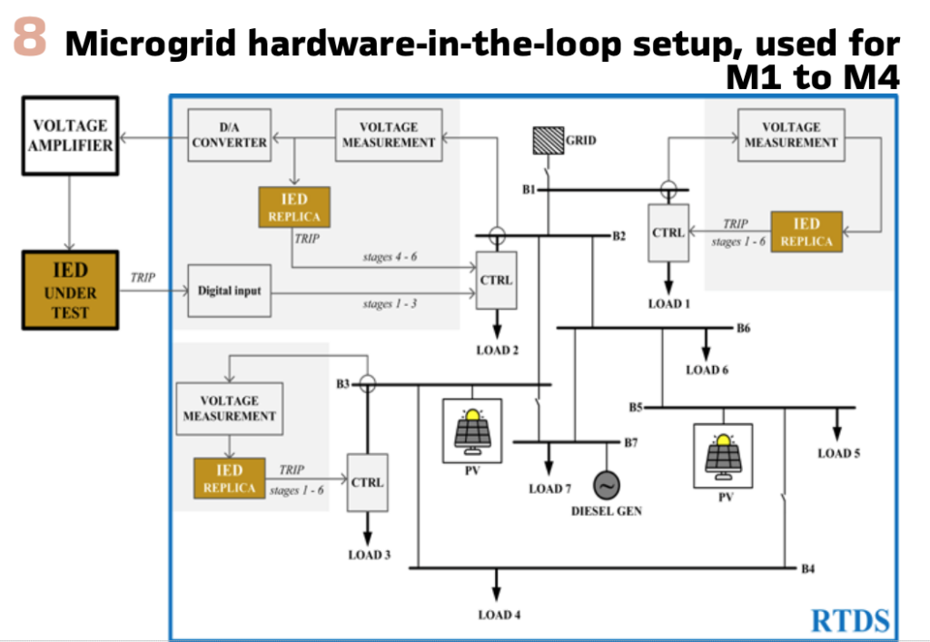
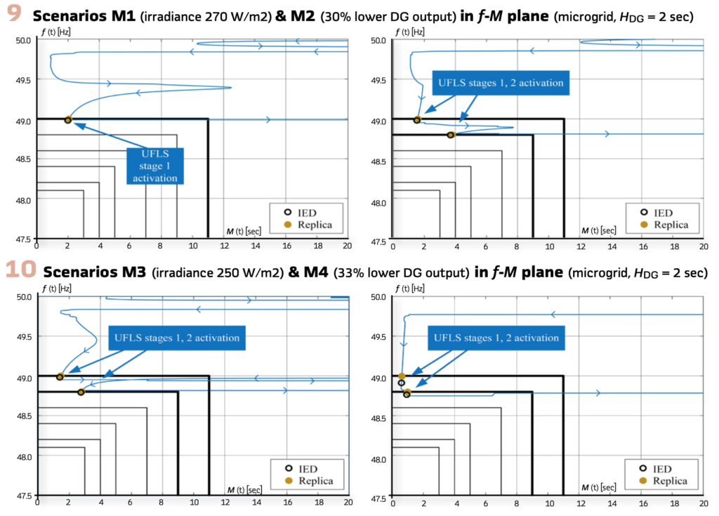
Hardware-in-the-loop Simulation Results – microgrid: Tests, performed by hardware-in-the-loop setup from Figure 8, were a subject to changes in i) inertial mass of a single diesel generator (DG), ii) solar irradiance affecting photovoltaic (PV) generation and iii) DG generation. A total of four scenarios were investigated. Scenarios M1 and M2 both consider inertia constant of DG to be HDG = 2 sec but differ in a cause of the power imbalance. In M1 the cause was decreased solar irradiance down to 270 W/m2, whereas in M2 the cause was a 30% decrease in DG output. Scenarios M3 and M4, on the other hand, both assume halving HDG = 1 sec. The difference between both is again in decreased solar irradiance down to 250 W/m2 (M3) and decreased DG output for 33%.
The difference between results of M1 and M2 is the activation of the second UFLS stage. Once the frequency reached the threshold value of 49.0 Hz, M(t) was less than 11 s in both cases, causing first stage activation. Estimated RoCoF at 49.0 Hz in both scenarios is -0.725 Hz/s and -0.960 Hz/s, respectively.
Both results indicate that IED and its digital replica tripped almost simultaneously, with just a slight difference occurring for the same reasons as above.
In both M3 and M4 scenarios, frequency is stabilized after the activation of two UFLS stages. This proves how sensitive microgrids are to any kind of variations in inertia and power imbalance. Frequency decay rate is larger (-1.09 Hz/s in M3 and -2.58 Hz/s in M4) and under such turbulent circumstances it is impossible to expect any significant improvements in terms of decreased amounts of tripping or smoother frequency response. On the other hand, we can confirm that the application of RoCoF did not introduce any undesired delays to the UFLS performance. In fact, RoCoF-based strategy behaves identically to a static UFLS. This confirms that implementing RoCoF in a described manner has no negative impacts on system security.
Conclusions
This article evaluates a new, adaptive RoCoF-based concept for emergency active-power balancing in electric power systems. Evaluation was performed using a hardware-in-the-loop testing principle, involving real-time digital simulator and an intelligent electronic device running the new algorithm.
Results obtained with two different power-system models (one of which is a microgrid with a significant share of inverter-based generation) confirmed more accurate power balancing compared to using static UFLS thresholds. The concept was proved to be robust and efficient despite involvement of RoCoF. The project helped to demonstrate that mainstream thinking, which involves many system operators, about RoCoF being unsuitable for emergency power balancing, is unjust.
Biographies:

Urban Rudez is a team member of Laboratory of electric power and supply in University of Ljubljana, Faculty of Electrical Engineering (Slovenia). His areas of interest include mainly power-system stability, power-system dynamic simulations and wide area measurement, protection and control applications. He is engaged in numerous research projects and an active member of CIGRE and IEEE. He (co)authored 28 original scientific papers and (co)presented more than 70 scientific contributions in domestic and international conferences.

Rajne Ilievska received B.Sc. degree in Electrical Engineering and Information Technologies from Ss. Cyril and Methodius University in Skopje, N. Macedonia in 2017, and in 2019 she received M.Sc. degree in Electrical Engineering from University of Ljubljana, Slovenia. She is currently working as a data scientist with the electricity distribution company Elektro Ljubljana in Ljubljana, Slovenia. Her areas of interest include data analytics and smart grids.

Denis Sodin received his B. Sc. and M. Sc. degrees in Electrical Engineering from the University of Ljubljana, Slovenia, in 2014 and 2017, respectively. Since graduation, he has been working at the Jozef Stefan Institute as a research assistant and at ComSensus as a research & innovation engineer and domain expert. His areas of interest include improvement of conventional under-frequency load shedding, applicability of PMU data for fault detection, localization/classification in power distribution networks and hardware-in-the-loop testing with a real-time digital simulator.

Janez Zakonjsek completed his M.Sc. studies at Faculty of electrical Engineering in Ljubljana, Slovenia in 1977.He started his international career as relay protection engineer at ISKRA company. In 1991 he joined former ABB Relays in Sweden, where he was active as Senior Application Specialist all around the world. In 1977 he also joined CIGRE organization where he participated actively in different working groups as a convener or regular member as well as within Slovenian and international CIGRE SC B5. Today he is active as independent consultant within his RELARTE company.

Rafael Mihalic received his Dipl. Eng., M.Sc. and Ph.D. degrees from Faculty of Electrical Engineering, University of Ljubljana, Ljubljana, Slovenia. He was a member of the Siemens Power Transmission and Distribution Group, Erlangen, Germany, a Visiting Researcher at ETH Zuerich and TEI of Crete. Since 2005 he is a full professor in the Department of Power Systems and Devices, head of Lab. for Electric Power Supply and leads the national research program Electric Power Systems. His areas of interest include power system dynamics and analysis and FACTS devices. He is a member of IEEE and a distinguished member of CIGRE.