Renewable Energy (RE) – Rich Grid
by Pankaj Kumar Jha, Brijendra B. Singh, Kuleshwar Sahu, Power Grid Corporation of India Limited, India
Introduction: The large-scale integration of IBRs into the Indian Grid is presenting new challenges for protection engineers. IBRs behave differently from traditional synchronous sources during short circuits. While short circuit currents from synchronous sources are high-magnitude and uncontrolled, IBRs produce low-magnitude, controlled currents managed by fast switching power electronics. This control ensures that short circuit currents are limited to avoid damaging power electronics but may not meet traditional protection expectations.
Conventional protection schemes, which rely on high-magnitude, inductive short circuit currents, may fail to operate properly when IBRs are involved, either tripping unnecessarily for external faults or failing to trip for internal faults. Additionally, weather conditions affect IBR output, further complicating protection reliability. This article aims to serve as a resource for protection engineers, helping them understand and address the protection challenges posed by the growing integration of renewable energy sources into the Indian Grid.
Section 2 of this article discusses briefly about the connectivity standards in India and scope of IEEE2800 as applicable to IBRs. Section 3 discusses protection challenges near RE generator ends, including issues with distance protection, carrier-aided protection, differential and directional protection. Section 4 real world case studies of protection mis-operation near IBRs. Section 5 explores protection coordination challenges in the Indian Grid due to widespread RE integration.
Connectivity standards in India and scope of IEEE2800
The connectivity standards in India, particularly those outlined by the Central Electricity Authority (CEA) and the Indian Electricity Grid Code (IEGC,) do not explicitly reference IEEE 2800. However, they establish requirements for the integration of IBRs, into the Indian power grid. These standards address key aspects like voltage and frequency ride-through, fault ride-through, power quality, and protection, which are also covered by IEEE 2800. While IEEE 2800 is not directly mentioned, its technical criteria and protection mechanisms for IBR integration, such as voltage and frequency support and fault current characteristics, align with India’s grid code and connectivity standards.
IEEE 2800 does not mandate specific protection types for IBR plants, it only requires that any protection applied, including for auxiliary loads, must enable the plant to meet its ride-through requirements. The standard addresses protection needs for frequency, rate of change of frequency (ROCOF), overvoltage, and overcurrent. Protection against unintentional islanding and interconnection system protection must comply with the Transmission System (TS) owner’s requirements, ensuring that IBRs operate safely and reliably within the grid.
Since IEEE 2800 does not specify any particular protection for IBRs at the Point of Common Connection (PCC), and neither the CEA connectivity standards nor the IEGC provide specific protection systems for IBRs at PCC, utilities continue to use distance and directional protection schemes designed for grids with large inertia and predominantly synchronous generation. These protection schemes often fail to operate correctly during faults due to the differing fault current characteristics of IBRs compared to synchronous generators. The next section will discuss the fault current characteristics of IBRs and the limitations of various protection systems near IBRs
Protection Challenges Near IBRs
The voltage at the IBR terminals is determined by the grid, while the fault current is limited by the inverter control characteristics, potentially causing differences in the frequencies of the fault current and fault voltage at the time of fault inception, which can impact phasor estimation in numerical relays and affect the performance relays near IBRs. It is also to be noted that the fault current contribution from IBR is low and limited by the inverter’s current rating and the amount of negative sequence current is minimal and depends upon grid code requirements. The effects of these fault current characteristics on different types of protection system is described below.
Effect on Distance Protection: Challenges with distance protection in IBRs arise due to several factors. The impedances seen by the protection system depend on the control strategies implemented in the IBRs, with reactive current requirements potentially causing impedances to appear farther from their actual values. The phase distance elements of zones 1 and 2 may overreach and drop out, respectively, due to oscillating apparent impedance caused by currents injected by the IBRs. Additionally, traditional polarization methods for direction determination often struggle to provide accurate results. There are also large variations between the phases of the fault current and voltage, leading to chaotic impedance trajectories, further complicating the operation of distance protection.
Effect on Differential Protection: Challenges in differential protection arise due to the angular difference between currents, where a phase-phase fault creates an angular difference of nearly 180° on the network side, while remaining around 120° on the IBR side, a result of control strategies during the FRT period. Differential relays on the IBR side face issues with line protection sensitivity, particularly in starting logic and phase detection. The low influence of current penetration, combined with the inverter control strategy, causes varying behaviour in each phase of the three-phase current system, as it depends on the voltage drop level in each phase, complicating accurate detection and protection. Still line differential is the preferred solution for the lines connected to IBRs.
Effect on Power Swing Block (PSB) and Out of Step (OST) Protection: Power swings are oscillations in power flow caused by system disturbances, such as faults, loss of synchronism, or changes in power flow direction. These disturbances can cause generators to accelerate or decelerate, leading to power swings. During a power swing, system voltages and currents change, and protective relays may mistakenly interpret these variations as faults, resulting in unnecessary equipment tripping. Power swing protection prevents this by distinguishing between a fault and a power swing, blocking relay operation during a swing.
The detection is based on the rate of change of swing impedance, which is slow during a swing due to the large rotational inertia of machines, but fast during a fault. Power swing protection includes two main functions: Power Swing Blocking (PSB), which differentiates faults from swings, and Out of Step Tripping (OST), which initiates system partitioning in case of an unstable swing. However, reduced inertia and changed dynamics under IBRs can alter the swing trajectory, leading to unintended results. (Figure 1).
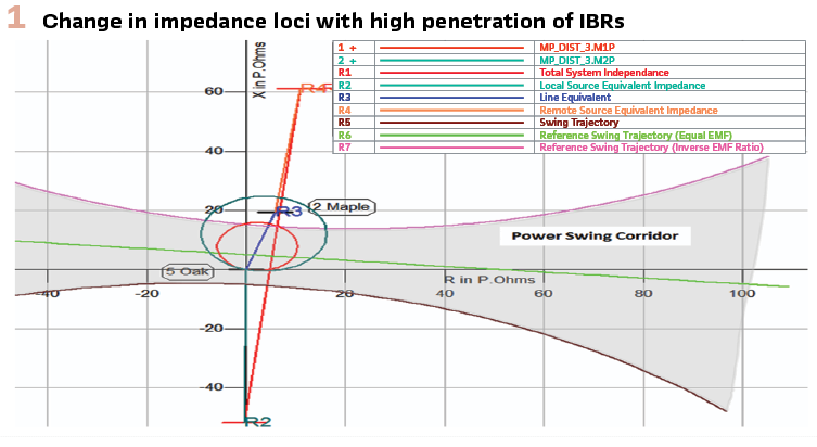
Power swing protection may mistakenly identify a fault instead of a power swing. One solution is to reduce the PSB time delay by identifying the fastest swing with IBRs, but this may block distance relay zones during faults. Additionally, altered swing impedance trajectories under IBRs can cause the OST to misinterpret a stable swing as unstable, leading to unnecessary system partitioning. Adjusting the inner characteristic settings based on the swing trajectory can prevent this issue.
Real World Case Studies from Indian Power Sector
In this section, we will discuss some cases of protection system mis-operation near IBRs in the Indian grid.
Mis-Operation of Distance Protection and Implementation of Weak-End Infeed Logic: Most RE generators are connected to pooling stations via 220kV transmission lines, with distance protection systems from two different vendors at both the grid and RE generator ends. POTT and PUTT are used for short and long lines, respectively. During faults near the RE generator ends, the limited fault current and negligible zero-sequence current prevent the operation of distance and directional earth fault protection. This results in fault clearance from the grid side in zone-2 time. Disturbance records (DR) extracted from the protection relays installed at both ends of the transmission lines are shown in Figures 2(a) and 2(b). These figures show the fault current contributions from both sides and the non-operation of protection at the RE end, causing delayed fault clearance. This delay, combined with the lack of protection at the RE side, increases stress on the grid-side auto transformers. To address this, weak-end infeed schemes with echo logic have been implemented at RE end relays.
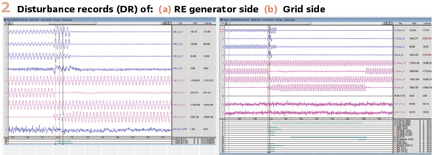
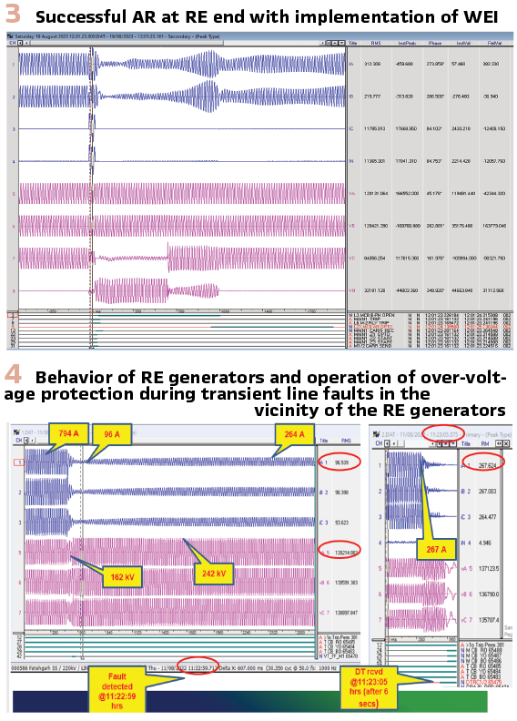
Figure 3 shows a recent DR where, after implementing weak-end infeed echo and trip logic, the protection relay at the RE end operated correctly during a fault near the RE generator. Additionally, the auto-reclosure (AR) functioned successfully at the RE end during the fault. This scheme has been applied to all lines connected to the RE generator.
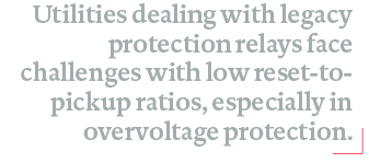
Mis-Operation of Over-Voltage Protection and Coordination of Over-Voltage Protection in the RE-rich region of Indian Grid: Utilities dealing with legacy protection relays face challenges with low reset-to-pickup ratios, especially in overvoltage protection. Current protection standards in India require overvoltage protection in both main-1 and main-2 relays on transmission lines, typically using two distance relays from different vendors or a mix of distance and differential relays. The variance in reset-to-pickup ratios across relays complicates this. While some relays allow adjustments, others have fixed ratios between 95% and 98%. After transient faults on transmission lines connected to RE pooling stations, momentary over-voltage can occur due to delayed recovery of active power from IBRs. Different reset-to-pickup ratios cause some relays to reset quickly, while others persist, leading to inadvertent tripping even if the voltage falls below the threshold. Similar issues arise in transformer over-excitation protection, where low reset-to-pickup ratios can trigger false operations. Figure 4 illustrates an event in the Indian Grid near the RE region, where transient line faults were cleared by the main protection relays within three cycles of fault inception. However, non-compliance with the grid code by RE generators caused delayed recovery of active power. Most transmission lines evacuating power from the RE-rich region in India are long 765kV EHVAC lines, which are connected to pooling substations with low short circuit ratios (SCR). The combination of low SCR and delayed recovery of active power leads to lightly loaded EHVAC lines after transient faults. This results in over-voltage pickup on many 765kV lines, and if the numerical relays have low reset-to-pickup ratio, over-voltage protection may operate erroneously. This incorrect operation causes outage of the evacuating path, triggering a cascading effect that leads to the tripping of multiple lines in the RE-rich region, despite the transient faults being cleared within three cycles.
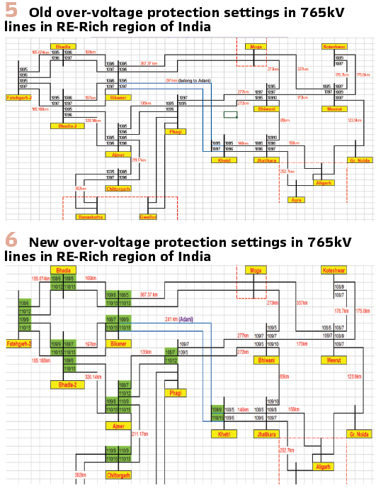
After several partial blackouts in India’s RE-rich region, over-voltage protection grading was conducted for all 765kV lines connected to the pooling substations. Figure 5 shows the over-voltage settings of the 765kV lines in the RE-rich regions of India prior to the partial blackouts.
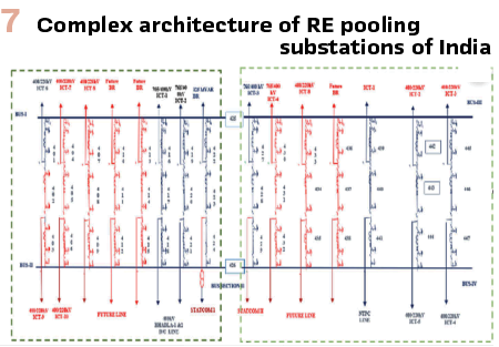
Figure 6 shows the over-voltage settings of the 765kV lines in the RE-rich regions of India implemented after the partial blackouts.
The reset-to-pickup ratio for over-voltage protection was set to 0.99 or better, where possible. If this setting was unavailable in the relay, additional logic was created to achieve a 0.99 ratio. If logic creation wasn’t feasible, grid operators were consulted to increase the over-voltage time delay settings where the reset-to-pickup ratio was high. With the implementation of over-voltage grading and adjustments to the protection settings, partial blackouts have been controlled, and no further blackouts occurred during recent transient line faults. Additionally, greater emphasis is placed on ensuring generator compliance with grid codes, fostering a collaborative approach for a more reliable grid.
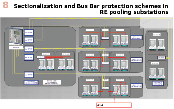
Problems in the Integration of Bus Bar Protection Schemes in the RE Rich Region of India: One issue during the planning stage is the construction of large number of bays after the initial commissioning of the RE pooling substations. These additional bays, required to connect more RE generators, lead to the sectionalization of bus bars in later stages. As the bays are added as separate projects, substations may end up with different makes of bus bar protection relays across various bus bar sections. In some substations, space constraints necessitate the use of outdoor and hybrid Gas-Insulated Switchgear (GIS) for power evacuation.
The complex architecture and layout of these substations create challenges in operation, maintenance, and the commissioning and integration of bus bar protection schemes in brownfield projects. An example of this issue is shown in Figure 7, where one of the RE pooling substations initially had eight diameters in a one-and-a-half CB scheme. This substation used vendor-A’s decentralized bus bar protection scheme.
According to POWERGRID’s philosophy, Main-1 and Main-2 protection from the same vendor were adopted for the bus bar protection scheme, connecting a total of sixteen bay units to the central unit. Over time, as additional bays were energized, the total number of bay units connected to the central unit exceeded the maximum limit of vendor-A’s system. Furthermore, when new bays were added as part of separate projects, decentralized bus bar protection scheme from a different vendor was used. A portion of Bus Bar protection scheme is shown in Figure 8.
To interface the new protection system with the old one, communication between bay units of vendor-A and central units of vendor-B was required, but this was not feasible. As a solution, the bus was sectionalized by installing a bus sectionalizers between the two buses, which improved operational flexibility.
This sectionalization required removing some existing bay units from vendor-A’s central unit and replacing them with new bay units from vendor-B. This process involved significant wiring modifications, engineering, and configuration changes in the bus bar relays.
The complexity of this process, combined with the limited shutdown durations in the RE-rich region, caused difficulties in configuring and testing the new bus bar protection schemes, resulting in several mis-operations in these pooling substations.
These types of problems could be avoided with proper planning and a more collaborative approach between different stakeholders.
Protection Coordination Challenges in the Indian Grid
Ensuring both dependability and security in transmission line protection is vital. Uncleared faults can lead to widespread tripping and grid disturbances, while unintended relay operations during system stress can cause cascading failures.
In Indian grid, distance protection is the primary protection and typically have three forward-looking zones and one reverse-looking zone. Backup directional earth fault (DEF) protection, coordinated with zone-3, addresses high-resistance faults.
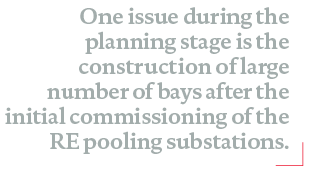
The DEF protection uses an IDMT (Inverse Definite Minimum Time) characteristic, with pickup currents of 200A for 400kV lines and 300A for 765kV lines. DEF operation times are coordinated with zone-3 times (typically 900ms, 1100ms, or 1600ms), with a 100ms safety margin. If the fault current is equal to or lower than the DEF setting, TMS becomes impractical (zero or negative). For transmission lines connected to RE generators, the low fault current makes setting TMS difficult, often resulting in very low TMS. This can cause issues during high-resistance faults.
The data of the fault current contribution from RE generators during single-line-to-ground (SLG) fault at two different substations are used for coordinating DEF protection in the transmission line. During an SLG fault, the zero-sequence current contributed by RE generators is zero.
See Figure 9 for the calculation of TMS for DEF protection for RE connected line at Substation-B.
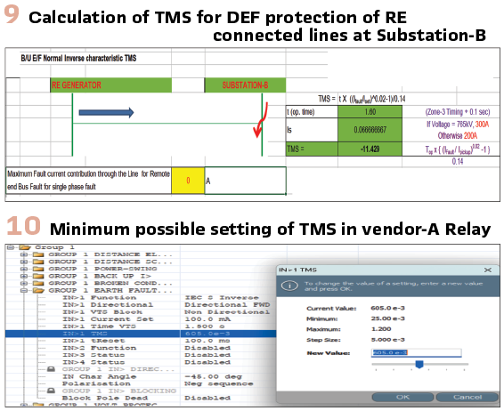
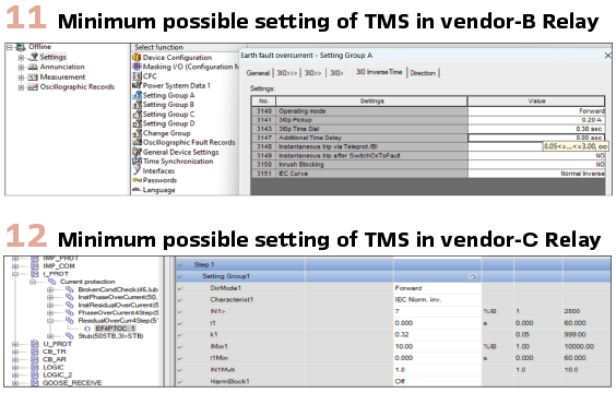
This small value of TMS shown in Figure 10 is impractical to implement in the modern numerical relays. Generally, the smallest minimum TMS available in the relay is selected for implementation. Figures 10, 11 and 12 show the minimum possible value of TMS in numerical relay of make-A, make-B & make-C respectively.
The minimum possible value for TMS is 0.025 in make-A relay, 0.05 in make-B relay and 0.01 in make-C relay.
The arbitrarily chosen minimum TMS can cause coordination issues between DEF protection and zone-3, leading to potential mis-operations. It’s important to note that the minimum TMS value varies between different relay manufacturers. With the rapid addition of RE to the Indian grid, accurate fault current data from RE is crucial for precise TMS calculation.
For transmission lines, this coordination issue can be avoided by using line differential protection. Similar coordination challenges occur with backup over-current and earth fault protection for the HV side of ICTs at the transmission utility end.
Conclusion
In conclusion, the integration of RE into India’s power grid has highlighted several protection challenges, particularly around IBRs. Protection schemes need to be adapted to account for the distinct characteristics of IBRs, such as low fault current contributions and the different behaviors of fault currents compared to traditional synchronous generators.
These differences have exposed weaknesses in traditional protection schemes, such as distance protection and over-voltage protection, leading to mis-operations and cascading tripping during transient faults.

Effective coordination of protection systems and more collaborative approach between stakeholders, along with better planning and updated protection mechanisms, is essential for improving grid reliability and minimizing operational risks in an increasingly RE-dependent grid.
Biographies.

Pankaj Kumar Jha is a senior power system professional with over 14 years of experience in control and protection engineering, secondary systems, and transmission network resilience. He currently works with POWERGRID, India where he has been deeply involved in the engineering, commissioning, and modernization of EHVAC and FACTS systems up to 765 kV. His area of expertise includes power system protection, post-fault analysis, IEC 61850–based substation automation, renewable energy integration, Digital Substations and grid code compliance. He is a Senior Member of IEEE and an active member of IET (UK) and CIGRE. He has contributed extensively to international technical literature through papers presented at CIGRE, DPSP, and global conferences across Europe, Australia, and Asia. His work focuses on real-world protection challenges in renewable energy–rich grids, system integrity protection schemes (SIPS), and lessons learned from large-scale utility operations.

Brijendra Bahadur Singh is an accomplished Power System engineer with over 15 years of experience in various domains of power sector. He started as carrier building transmission systems at site and commissioned 765kV substations, multiple FACTS devices, Transformers and Reactors. He also worked as Grid Operator of Indian Electricity Grid. His areas of interest are Power System Protection, Virtualized Protection, Reducing Carbon footprint of transmission system, and Asset Management. He is an active member of CIGRE and a part of WGC3.25 and WGB5.81.

Kuleshwar Sahu has over twenty-five years of experience in the Indian power sector, with extensive expertise in asset management, digitalization, project management, and power system operation. He has been instrumental in adopting digital technologies and driving digital innovations in POWERGRID. He has published several papers and delivered numerous talks on asset management, power system operation, and digitalization of the power grid, both in India and internationally.