Ebrahim Balouji, EcoPhi AB, Eneryield AB, Sweden
The global transition towards renewable energy sources has significantly increased the integration of inverter-based generation systems, such as solar photovoltaic (PV) farms, into existing power grids. While this shift contributes to environmental sustainability and reduces dependency on fossil fuels, it also introduces new challenges related to power quality and grid reliability. One of the primary concerns is the generation of high-order harmonics due to the switching operations of power electronic inverters used in these renewable energy systems. High-order harmonics are voltage or current components with frequencies that are integer multiples of the fundamental frequency (50 Hz or 60 Hz). Inverter-based generation systems can produce harmonics extending into the kilohertz range because of their high-frequency switching mechanisms. These harmonics can have detrimental effects on power system components, particularly transformers, by causing increased losses, overheating, and accelerated aging, ultimately leading to failures.
Literature Survey: Integrating inverter-based renewable energy sources, particularly solar photovoltaic (PV) systems, has introduced significant challenges related to harmonic distortions in power systems. Numerous studies have investigated the impact of these harmonic distortions on power system components. The widespread use of power electronic converters in renewable energy installations introduces substantial harmonic content into the grid, adversely affecting the performance and lifespan of electrical equipment.
Guidelines for harmonic control in electrical power systems, such as IEC 61000-3-6, emphasize limiting harmonic distortion levels to protect equipment and maintain power quality. High-order harmonics generated by solar inverters can significantly increase eddy current losses and stray flux in transformers, leading to excessive heating and insulation degradation. Analyses of transformer failures in regions with high penetration of PV systems have concluded that high-order harmonics from inverter switching frequencies are significant contributing factors.
Estimating and measuring high-order harmonics pose challenges due to the limitations of conventional monitoring equipment.
Traditional measurement devices, including standard merging units (MUs), are typically designed to capture harmonic components up to the 50th order, with sampling rates around 4,000 samples per second (4 kHz). According to the Nyquist theorem, this sampling rate cannot accurately detect higher-frequency distortions associated with harmonics above the 50th order.
Several vendors offer MUs with varying sampling rates to address this limitation. For instance, some provide a merging unit, which samples at a rate of 4 kHz. While suitable for essential protection and control, this sampling rate limits the detection of high-order harmonics. Another offers a merging unit, operating with a sampling rate of 12.8 kHz. This higher sampling rate improves harmonics detection up to the 64th order in a 50 Hz system. An AI-powered Merging Units (QMU) offers merging units capable of sampling at 1.5 MHz, compliant with IEC 61869-9 standards. This high sampling rate allows for accurate harmonics detection up to the 100th order in a 50 Hz system.
Advancements in international standards, such as IEC 61869-9, have facilitated the development of high-sample-rate MUs capable of sampling voltage and current at rates necessary for accurate harmonic analysis. Implementing high-sampling-rate measurement devices is essential for maintaining power quality and ensuring the reliability of power system components, especially in the context of increasing renewable energy integration.
Case Study: Transformer Failures Due to High-Order Harmonics from a Solar Farm
In this study, we focus on a substation that experienced the failure of three transformers following the installation of nearby solar farms. The transformers exhibited overheating and insulation breakdown, leading to catastrophic failures. Initial investigations ruled out overload conditions and manufacturing defects, prompting a detailed analysis of the substation’s power quality.

By deploying IEC 61869-9-compliant high-sample-rate MUs, we captured detailed voltage and current waveforms. The analysis revealed significant high-order harmonic content between the 60th orders, corresponding to frequencies between 3 kHz in a 50 Hz system. These harmonics were traced back to the switching frequencies of the inverters used in the solar farms.
These high-order harmonics increased the eddy current and hysteresis losses in the transformers, causing excessive heating. Over time, this led to the degradation of the insulation materials and ultimately resulted in transformer failures. The findings highlight the critical need for high-sample-rate measurement and monitoring systems to detect and mitigate such issues effectively.
By adjusting the switching frequencies of the inverters, we reduced the amplitude of the problematic harmonics, mitigating the adverse effects on the transformers. This solution was implemented without significant additional costs, demonstrating the effectiveness of coordinated actions between utility operators and renewable energy providers.
This article aims to:
- Highlight the impact of high-order harmonics generated by inverter-based energy systems on power transformers
- Demonstrate the necessity of high-sample-rate MUs to detect and mitigate high-order harmonics accurately
- Present a case study where transformer failures were successfully mitigated by adjusting inverter switching frequencies enabled by deploying IEC 61869-9-compliant MUs
- Emphasize the importance of standards and advanced measurement technologies in ensuring the reliability and efficiency of modern power systems with high penetration of renewable energy sources
In the following sections, we will delve deeper into the methodology used to detect and mitigate the high-order harmonics, present the results of our intervention, and discuss the broader implications for power system operations and renewable energy integration.
Methodology
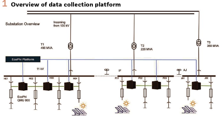
Data Collection Platform: The study was conducted on an 11 kV substation that serves as the interconnection point for three solar farms with 100 MW, 80 MW, and 70 MW capacities, respectively. The substation is configured with three transformers and three busbars, each transformer connecting one of the solar farms to the grid via its dedicated busbar. This setup allowed for isolated analysis of each solar farm’s impact on the substation while observing the cumulative effects on the power system.
QMUs were installed at the substation to monitor the harmonic content introduced by the inverter-based solar farms. These devices comply with the IEC 61869-9 standard. It can sample both voltage and current at 1.5 MHz/28.8 kHz/14.4 kHz/4.8 kHz and stream the sample values to a the EcoPhi platform in a substation where VPMU is installed. Following the IEC 61869-9 standard, the sampled values from the QMUs are packaged into Sampled Value (SV) messages to ensure efficient data transmission and synchronization within the digital substation. To maintain a consistent message rate of 600 messages per second across different sampling rates, the number of samples per message is adjusted accordingly. For a sampling rate of 4.8 kHz, which corresponds to 96 samples per cycle in a 50 Hz system, each SV message contains 8 samples.
This ensures that 600 messages are transmitted every second, optimizing communication bandwidth and minimizing latency. At a higher sampling rate of 14.4 kHz, yielding 288 samples per cycle, the number of samples per message is increased to 24, maintaining the same message rate of 600 messages per second. Similarly, at the 28.8 kHz sampling rate used in this study, producing 576 samples per cycle, each SV message includes 48 samples, sustaining the message rate at 600 messages per second. For the extremely high sampling rate of 1.5 MHz, which generates 30,000 samples per cycle, each SV message is packaged with 2,500 samples to maintain the consistent message rate of 600 messages per second. As IEC 61869-9 recommended, this standardized packaging approach ensures that data transmission remains efficient and synchronized, facilitating accurate harmonic analysis and real-time monitoring without overwhelming the communication network. The high sampling rate enables the precise detection of harmonics up to the 100th order in a 50 Hz system, as per the Nyquist criterion, which states that the sampling frequency (fs) must be at least twice the maximum frequency (fmax) of interest.
Therefore, the sampling frequency of 28 kHz exceeds the minimum required 10 kHz, providing ample resolution for harmonic analysis up to the 100th order. Besides the harmonics, other power quality (PQ) parameters, such as events and variations according to IEC 61000-4-30 standards, are on the platform in a virtualized fashion. The platform also includes virtualized PMU and partial discharges, collecting temperature from each feeder, including the busbar. The same feeders are connected to a third-party merging unit capable of sampling voltage and current at 4 kHz to compare the scenario. The overall overview of the substation with three busbars and transformers is illustrated in Figure 1.
Harmonic Extraction Using FFT: The extraction of harmonic components from the collected voltage and current signals was performed using the Fast Fourier Transform (FFT). The FFT is a computational algorithm that efficiently computes the Discrete Fourier Transform (DFT), converting time-domain signals into their frequency-domain representations.
Voltage and current signals were sampled continuously over a period corresponding to 10 cycles of the fundamental frequency. With a sampling frequency of 28 kHz, the total number of samples (N) per measurement window is 5,600. A Henning window function was applied to the sampled data to reduce spectral leakage and improve the accuracy of the FFT.
The high sampling resolution ensures that harmonics are accurately identified at integer multiples of 50 Hz up to the 100th order (5,000 Hz).
Mitigation Method: Synchronization of Inverter Switching Frequencies: A mitigation strategy was implemented to synchronize the inverters’ switching frequencies to address the high-order harmonics detected. By aligning the switching frequencies and phases of the inverters across the three solar farms, it is possible to cancel specific harmonic components through destructive interference.
Principle of Harmonic Cancellation: Inverters operating at different switching frequencies generate harmonic currents at multiples of their respective frequencies. When these harmonics coincide in the frequency domain but have phase differences, their superposition can result in constructive or destructive interference.
For the n-th harmonic, the total harmonic current In(t) from all inverters is the sum of individual contributions:
In(t) = ∑ [In,i × sin (2πn f (fundamental) t + φn,i)],
for i = 1 to 3
- In,i is the amplitude of the n-th harmonic current from inverter i.
- φn,i is the phase angle of the n-th harmonic from inverter i.
To achieve cancellation, the inverters are adjusted so that their harmonic currents are out of phase by 180 degrees (or π radians), leading to:
In,1+ In,2 + In,3 ≈ 0
This requires precise control of the switching frequencies fsw,i and the synchronization of their control signals.
Implementation Steps:
1. Determination of Dominant Harmonics: Analyze the harmonic spectra to identify which harmonic orders contribute most to transformer heating.
2. Adjustment of Switching Frequencies: Set the switching frequencies of all inverters to an expected value or to harmonically related values, ensuring that their generated harmonics align in frequency.
3. Phase Synchronization: Advanced control algorithms were implemented to synchronize the firing pulses of the inverters. This synchronization ensured that the phase angles of the harmonics from each inverter were precisely adjusted to facilitate destructive interference. The adjustment process was managed internally within each inverter based on recommendations derived from the harmonic analysis performed by the QMU.
4. Harmonic Modeling: Mathematical models predict the resultant harmonic levels after synchronization. The harmonic current from each inverter can be modeled as:
In,1 = Ih,1× sin (2πn f (fundamental) t + φi)
Where Ih,1 is the harmonic current magnitude, and i is the phase angle for inverter i
5. Optimization: Adjust i to minimize the total harmonic current In(t) at the critical harmonic orders. This can be formulated as an optimization problem:
Minimize over φ1, φ2, φ3:
| ∑ [ In,i × e^( jφi) ] |, for i = 1 to 3
6. Simulation and Verification: Simulate the inverter operations with the new settings to verify the expected harmonic cancellation before field implementation.
Results
Voltage Waveform Analysis: Voltage waveforms were recorded at the substation using two different sampling rates: 4 kHz and 28.8 kHz. The waveform recorded at 28.8 kHz provided a higher resolution, allowing a more detailed observation of the voltage signal. Notably, the switching frequencies associated with the inverters were visible and could be identified in the high-resolution waveform. This visibility is crucial for accurate harmonic analysis and subsequent mitigation efforts.
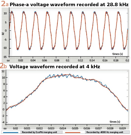
Figure 2 (a) illustrates the phase-a voltage waveform recorded at 28.8 kHz, showcasing the discernible switching frequencies resulting from the inverter operations. The fine details captured in the waveform enable the detection of transient events and high-frequency components essential for diagnosing power quality issues. Figure 2 (b) presents the voltage waveform recorded at 4 kHz, highlighting the absence of visible switching frequencies due to limited sampling resolution. The inability to observe these components can lead to missed detection of critical harmonic distortions.
In contrast, the waveform recorded at 4 kHz lacked the necessary resolution to capture the high-frequency components introduced by the inverter switching. As a result, the switching frequencies were not discernible in the lower-resolution waveform, making it insufficient for detecting high-order harmonics that may affect transformer performance.
FFT Analysis of Voltage Waveforms: The Fast Fourier Transform (FFT) was applied to both waveforms to analyze their frequency content. The FFT results for the waveform sampled at 28.8 kHz revealed significant harmonic components between the 65th and 80th orders, corresponding to frequencies between 3,250 Hz and 4,000 Hz in a 50 Hz system. These high-order harmonics were attributed to the switching frequencies of the inverters at the solar farms.
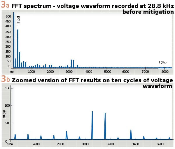
Figure 3 (a) shows the FFT spectrum of the voltage waveform recorded at 28.8 kHz before mitigation, highlighting the presence of harmonics around the 60th. The high sampling rate allowed for the accurate quantification of these harmonics, which are critical in diagnosing the cause of transformer overheating. Figure 3 (b) zoomed version of FFT results on ten cycles of voltage waveform.
The detailed harmonic spectrum allowed for precise identification of the problematic harmonic orders contributing to transformer stress.
In contrast, due to the limited sampling rate, the FFT results for the waveform sampled at 4 kHz did not show the presence of harmonics beyond the 40th order. According to the Nyquist criterion, the maximum frequency that can be accurately represented is half of the sampling rate. For a 4 kHz sampling rate, this limit is 2 kHz, corresponding to the 40th harmonic of a 50 Hz system.
As shown in Figure 4, the high-order harmonics cannot be estimated on the FFT of waveform recorded by 4kHz sample rate.
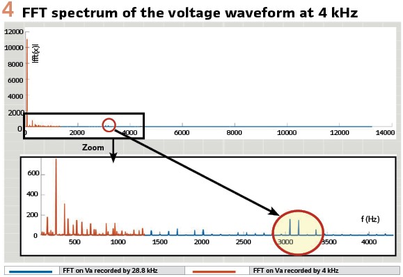
Figure 4 illustrates the FFT spectrum of the voltage waveform recorded at 4 kHz, demonstrating the absence of high-order harmonics beyond the 20th order. This limitation underscores the inability of low-sample-rate measurements to detect and analyze high-order harmonics that can adversely affect power system components.
Harmonic Mitigation Results: After implementing the mitigation method—synchronization of the inverters’ switching frequencies—the high-order harmonic content around the 60th order (the most present high other harmonics see Figure 3) is significantly reduced. The inverters’ switching frequencies were adjusted and synchronized to achieve destructive interference of the problematic harmonics.
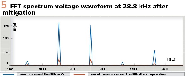
Figure 5 depicts the FFT spectrum of the voltage waveform recorded at 28.8 kHz after mitigation, showing a substantial reduction in harmonics around the 60th order. The amplitudes of these harmonics were reduced by an average of 70%, effectively mitigating the adverse effects on the transformers.
Transformer Performance Improvement: Reduced high-order harmonic content resulted in a noticeable improvement in transformer performance. Thermal measurements indicated a decrease in the operating temperatures of the transformers, reducing the risk of overheating and insulation degradation. No further transformer failures were reported following the implementation of the mitigation strategy.
Discussion on Results: The results highlight the critical role of high sampling rates in detecting and mitigating high-order harmonics in power systems with significant inverter-based generation. Using a 28.8 kHz sampling rate enabled the accurate detection of harmonics up to the 100th order, which was impossible with the conventional 4 kHz sampling rate.
The high sampling rate offers several advantages over lower sampling rates. Enhanced harmonic detection is one of the primary benefits, as high sampling rates allow for capturing higher-frequency components, enabling the detection of high-order harmonics that can cause equipment stress and failures. Improved diagnostic capability is another advantage, as detailed waveform data facilitate more accurate analyses of power quality issues, including transient events and harmonic distortions. Additionally, high sampling rates support preventive maintenance strategies by identifying potential issues before they lead to equipment failures.
In contrast, low sampling rates fail to capture critical high-frequency information, potentially leading to undiagnosed issues and unexpected equipment failures. The inability to detect high-order harmonics hampers efforts to maintain power quality and system reliability.
Implementing high-sample-rate Merging Units in digital substations represents a minimal investment compared to the cost of equipment failures and system downtime. Digital substations with advanced monitoring capabilities provide real-time monitoring, allowing operators to continuously observe system conditions with high-resolution data. The compliance of these devices with standards like IEC 61869-9 ensures interoperability with other digital equipment and systems, facilitating seamless integration. Furthermore, digital substations are scalable, as they can be easily upgraded or expanded to accommodate future technological advancements and increased data requirements.
The mitigation strategy implemented in this study—synchronization of inverter switching frequencies—was achieved with minimal additional cost. By adjusting the control settings of the existing inverters, the high-order harmonics were effectively canceled out through destructive interference. This approach avoided expensive hardware solutions such as passive filters or transformer replacements. The cost savings are significant, as reducing harmonic levels lowers the thermal and electrical stress on transformers and other equipment, extending their operational life. Preventing transformer failures eliminates the need for costly replacements and associated labor costs, and improved power quality enhances the overall efficiency of the power system, reducing losses and improving reliability.

The successful mitigation of high-order harmonics facilitates the integration of renewable energy sources into the power grid. Addressing harmonic issues ensures that inverter-based resources can operate without adversely affecting the grid, promoting smoother integration. Meeting power quality standards is essential for connecting renewable energy projects to the grid, and effective harmonic mitigation helps achieve compliance. Reliable operation of renewable energy sources without causing power quality problems increases public and stakeholder confidence in renewable energy initiatives. We observed that the suggested mitigation reduced the level of harmonics around 60th by an average of 70%, which is a significant improvement without adding any sort of filter, which is costly.
Conclusion
Integrating inverter-based renewable energy sources like solar farms into the power grid presents significant challenges to power quality and equipment reliability. This study focused on an 11 kV substation connected to three solar farms, where high-order harmonics from inverter switching frequencies led to the failure of three transformers. The research demonstrated the critical role of high-sample-rate Merging Units (MUs) in detecting and mitigating these issues.
By sampling voltage waveform at 28.8 kHz, the study accurately detected harmonics up to the 100th order, particularly problematic harmonics around the 60th order that conventional 4 kHz equipment could not observe. Fast Fourier Transform (FFT) analysis of the high-resolution data provided a detailed harmonic spectrum, facilitating precise identification of the harmonic orders contributing to transformer stress and overheating.
The mitigation strategy involved synchronizing the switching frequencies of the inverters across the three solar farms. This approach effectively canceled out the problematic harmonics through destructive interference, reducing their amplitudes by an average of 70%. The solution was implemented with minimal additional cost by adjusting the control settings of existing equipment rather than installing new hardware.
The results underscore the importance of high-sample-rate MUs in modern power systems, especially in environments with a high penetration of inverter-based generation.
Beyond harmonic detection and mitigation, these devices enhance overall monitoring and diagnostic capabilities, support real-time analysis, and enable proactive maintenance strategies. They can function as virtualized Phasor Measurement Units (VPMUs), providing high-precision synchro phasor data crucial for real-time monitoring, state estimation, and stability analysis. Additionally, they support Dynamic Line Rating (DLR) applications, enabling more efficient infrastructure utilization.
Biography:

Ebrahim Balouji – Grid Automation, Sweden, having overall 14 years of experience. He is the CEO and Co-Founder of Eneryield AB and the Founder of EcoPhi AB, companies that specialize in developing AI-driven merging units (QMUs) and fault prediction technologies. Dr. Balouji holds dual Ph.D. degrees in Electrical Power Signal Processing and Artificial Intelligence from Chalmers University of Technology, Sweden. He has 4 patents in his name.