by Alexander Apostolov, PAC World, Los Angeles, USA
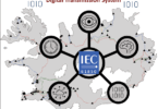
One of the main characteristics of Smart Grids is the high level of penetration of distributed energy resources (DERs) (see Figure 1) and the requirements for improved reliability of the electric power system under different abnormal conditions. The DERs are of different sizes and types and are being connected at all different levels of the electric power system – transmission, distribution and low voltage.
This introduces significant challenges for protection systems at the transmission and distribution level of the grid which need to be considered in the engineering of the protection devices and systems.
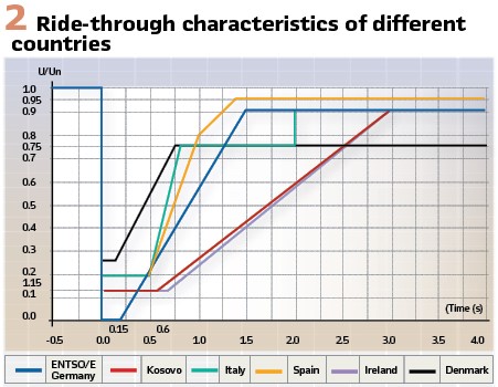
In order to remain in service following a short circuit fault the DERs need to be able to withstand the voltage drop until the fault has been cleared by the protection and the circuit breaker. This is defined by ride-through characteristics that are different for different countries, as shown in Figure 2.
The ride-through characteristic includes two areas defining the required response of the DER when a short circuit or another abnormal condition occurs.
The first area is the ride-through area when for a short period of time after the fault inception and depending on the level of the voltage drop the DER should stay connected to the grid.

The second area is where the DER can trip if the voltage drop is deeper or lasts longer.
The voltage drop is something that we cannot control, but we have to study in order to be able to predict or estimate the effects of different faults on the sensitive equipment. The second characteristic of the voltage sag – duration – is the parameter that we can control by properly applying the advanced features of multifunctional protection relays.
Considering that the protection operating time depends on the type of protection, location of the fault, type of fault and fault parameters, it is clear that these factors need to be analyzed in order to identify the requirements for improvement in the fault clearing time.
High speed protection can typically be achieved by communications-based schemes; however, the loss of the communications channel may have a negative impact on the fault clearing time.
One of the benefits of IEC 61850 based digital substations is the availability of streaming sampled values that can be used by different protection applications.
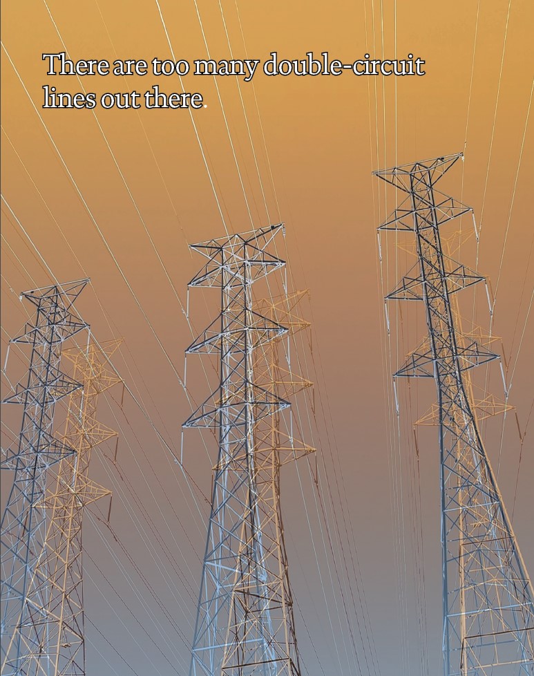
This article presents the implementation of a cross-differential protection function in a digital substation. It is suitable for double circuit transmission lines.
The first part of the article introduces the basic principle of cross-differential protection and describes its behavior for internal or external faults in case of double circuit transmission lines.
The second part of the article describes the implementation of cross-differential protection in digital substations and how it can be done in a centralized substation protection system as well.
Combining different non-communication-based protection functions in an integrated double circuit transmission line protection device is also presented in the article.
Implementation based on superimpose components or sampled values are described later in the article.
The last part of the article discusses the testing of the cross-differential protection function and the benefits of its application. The better coverage of instantaneous protection without the need of a communication channel is identified as a significant advantage that it offers. This can help improve the stability of the electric power grid as well as support the ride-through of distributed energy resources in case of short circuit faults on double circuit transmission lines.
Cross-differential Protection Principle
Differential protection is a principle widely used in the protection of electric power systems. It operates on the idea of comparing the currents entering the protection zone to the currents leaving it. In an ideal scenario without a fault these currents are equal. However, when a fault occurs within the protected zone, this balance is disrupted, leading to a differential current that triggers the protection mechanism.
Line differential protection remains the most selective form of protection for multiple circuit line protection as it is immune to phenomena such as mutual coupling. However, communications requirements may be cost prohibitive so solutions that can reduce the fault clearing time but without the communications requirements are advantageous. One such solution is the cross-differential protection scheme shown in Figure 3.
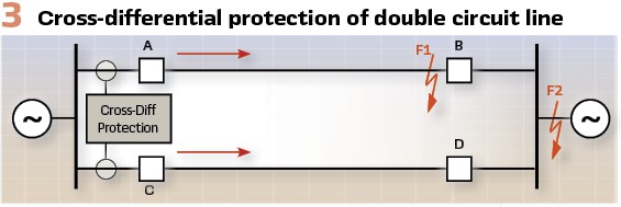
Cross-differential protection extends the basic differential protection principle to protect double circuit transmission lines by comparing currents from both circuits in its operating principle. It involves measuring the incoming and outgoing currents on both circuits and then comparing these measurements to detect the presence of internal faults.
The essence of cross-differential protection lies in its ability to differentiate between internal faults (within the protected zone) and load or external faults (outside the protected zone) by analyzing the currents in both circuits. It calculates the differential current for each circuit and also cross-compares the currents between the two circuits.
This approach enhances sensitivity and selectivity, especially in complex fault scenarios where traditional transmission line protection might struggle.
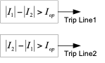
The fundamental principle of the traditional cross-differential element is based on the calculation of the difference between the magnitude of the currents of the two lines to determine whether a fault is internal or external and select the faulted line.
Under load conditions or external fault conditions the difference between the currents in both circuits will be minimal, while after a fault occurs on one of the lines there will be a difference between the currents in the faulted and the healthy circuit.
If the magnitude of the current in line 1 is greater than the magnitude of the current in line 2 this means that line 1 is the one with the short circuit fault.
If the magnitude of the current in line 2 is greater than the magnitude of the current in line 1 this means that line 2 is the one with the short circuit fault.

The difference between the currents in the two parallel circuits during the different short circuit fault conditions depends on different factors such as the sources at both ends of the double circuit transmission line, the type of the fault and its location. All of this needs to be carefully analyzed in order to define the value of the operating cross-differential current setting.
Since typically the transmission lines protected by distance protection covers about 80% of the line with the instantaneous zone 1 and the remaining by time delayed zone 2, the focus of the following analysis will be if we can reduce the fault clearing time without the use of communications based accelerated protection schemes and clear faster short circuit faults at the end of the protected double circuit transmission line.
The results from short circuit single phase to ground fault simulations at different locations close to the end of line 1 are ddiscussed and one is shown in Figure 4. For the first three figures the simulations are based on a SIR 2.5 for the source in substation A and SIR 5.0 for the source in substation B.
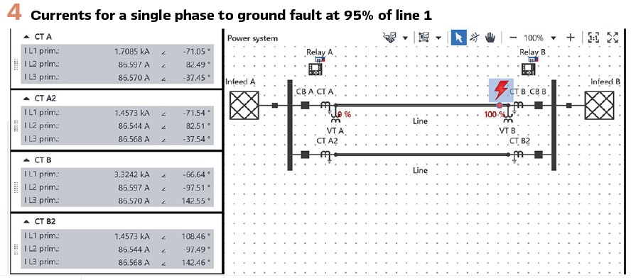
Figure 4 shows the three phase currents of all breakers of the two circuits at both ends of the lines. This gives a good idea of the differences in the magnitude and direction of the currents that can be used to determine the operating setting depending on the algorithm used by the cross-differential protection.
If we analyze the currents through all the breakers for a single phase to ground fault at 95% of the line shown in Figure 4, we will see that at substation A the currents in the faulted phase on both lines are in the forward direction into the line. The difference between the magnitude of the currents in line 1 (CT A) and line 2 (CT A2) is about 250 amps indicating that the fault is on line 1 assuming that the operating setting Iop for the cross-differential element is 150 amps.
For the cross-differential element at substation B the currents in the faulted phase on both lines are in opposite direction – forward into the line for CT B and reverse for CT B2 . The difference between the magnitude of the currents in line 1 (CT B) and line 2 (CT B2) is about 1900 amps indicating that the fault is on line 1.
The magnitude of the current in line 1 (CT B) is the result of the addition of the fault currents from line 2 (CT B2) and from Infeed B.
As a result, both breakers A and B will be tripped without additional time delay clearing the fault on line 1.
If we perform the same analysis for the currents through all the breakers for a single phase to ground fault at 97% of the line, we will see that at substation A the currents in the faulted phase on both lines are in the forward direction into the line. The difference between the magnitude of the currents in line 1 (CT A) and line 2 (CT A2) is about 160 amps indicating that the fault is on line 1 assuming that the operating setting Iop for the cross-differential element is 150 amps.
For the cross-differential element at substation B the currents in the faulted phase on both lines are in opposite direction – forward into the line for CT B and reverse for CT B2. The difference between the magnitude of the currents in line 1 (CT B) and line 2 (CT B2) is about 1800 amps indicating that the fault is on line 1.
As a result, both breakers A and B will be tripped without additional time delay clearing the fault on line 1.
Things change when the faults get very close to the end of the line. If we look at the currents through all the breakers for a single phase to ground fault at 99% of line, we will see that at substation A the currents in the faulted phase on both lines are almost identical. The difference between the magnitude of the currents in line 1 (CT A) and line 2 (CT A2) is about 50 amps which is well under the operating setting Iop for the cross-differential element.
For the cross-differential element at substation B the currents in the faulted phase on both lines are in opposite direction – forward into the line for CT B and reverse for CT B2. The difference between the magnitude of the currents in line 1 (CT B) and line 2 (CT B2) is about 1800 amps indicating that the fault is on line 1.
As a result, breaker B will be tripped without additional time delay, however this is not the case with breaker A which will not trip at the same time. The fault current distribution changes with some fault current from the source in B going through line 2 and with higher fault current now going through line 1. This will lead to the cross-differential current in substation A being way above the operating setting Iop resulting in the sequential tripping of breaker A. The delay of the operation of the cross-differential protection in substation A in this case will depend on the opening time of breaker B which is still much faster than the zone 2 fault clearing time if we use only distance protection on the double circuit line.
This technique offers a considerable benefit since it allows in most cases fast fault clearing for faults on any of the lines. The instantaneous tripping zone covers a large section of the protected line with the remainder of the line covered by sequential tripping which is faster than the Zone 2 distance operation.
Cross-differential Protection Implementation in Digital Substations
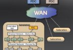
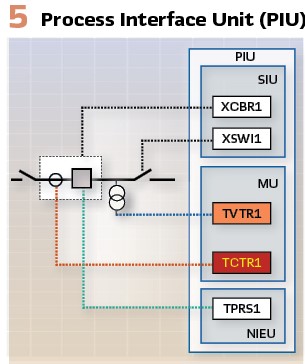
The digital transformation of the electric power industry based on the IEC 61850 standard provides opportunities for the implementation of cross-differential protection in digital substations. They are distributed hierarchical systems using IEC 61850 object models and communications. This is because the digitization of the analog and binary signals from the substation equipment in the yard is performed by different devices that are connected to the substation PACS using fiber optic cables. These devices we can call process interface units (PIU).
The process interface devices can be with different levels of complexity depending on which process interface functions they are implementing.
For the digital PACS we use the following naming conventions:
- Merging Unit (MU) converts analog signals (currents and voltages) into time-synchronized streams of sampled values according to IEC 61850-9-2 of IEC 61869-9
- Switchgear Interface Unit (SIU) provides a binary status and control interface for circuit breakers and switches
- Non-Electric Interface Unit (NEIU) converts analog signals from non-electric sensors into time-synchronized streams of sampled values according to IEC 61850 9-2 or GOOSE messages according to IEC 61850-8-1
- Process Interface Unit (Figure 5) combines two or more of the functions listed above
The different process interface units communicate with the substation PACS using the required IEC 61850 services. The communications architecture depends on the specifics of the substation and the requirements for performance, reliability and security. Redundancy protocols such as PRP are used to improve the reliability of the system.
All components of the PACS are time-synchronized based on IEC 61850-9-3 (a PTP profile).
For the implementation of the cross-differential protection function we need at each end of the protected double circuit transmission line to interface with two PIUs – one for line 1 and the second for line 2. Typically, they will be duplicated for redundancy.
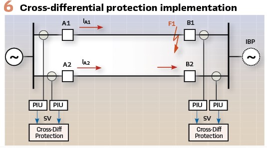
The device implementing the cross-differential function (Figure 6) will subscribe to the sampled values and GOOSE published by the PIUs and it will also send a GOOSE message to the appropriate PIU when a fault is detected on one of the protected circuits to trip the breaker and clear the fault.
The cross-differential function will operate based on the streaming sample values. In the traditional implementation a MMXU logical node will be used to calculate the magnitude of the currents on each of the double circuits and based on these values it will be determined if there is a fault within the zone of protection.
Based on the sample values it is possible to also implement more advanced algorithms using superimposed components of the currents or instantaneous values provided by the individual samples. When using samples, it is possible to detect the fault condition much faster in the range of a few milliseconds while using a sampling rate of 80 samples per cycle. In this case the cross-differential elements subtract the value of each specific samples from the two circuits and makes a decision which is the faulted circuit using for example 5 consecutive samples-based calculations.
Combining different non-communication-based protection functions such as cross-differential, distance and directional ground overcurrent in an integrated double circuit transmission line protection device provides significant reduction in the short circuit fault clearing time without the need for use of a communication channel.
Cross-differential Protection Testing
From the discussions in the previous sections of the article it is clear that the protection of a double circuit line needs to be able to operate under different system conditions, evolving and cross-country faults, sequential tripping conditions and under the influence of mutual coupling. All of the above needs to be considered in the testing of such protection devices for communications-based or non-communication schemes.
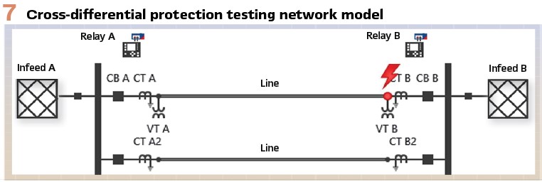
The testing requires the use of advanced testing tools and software that can simulate the different system conditions and status of primary substation equipment, the mutual coupling between the parallel lines and the signals from other multifunctional IEDs protecting the parallel lines. The testing system should be capable of simulating the streams of samples values for the currents and voltages on both circuits at both ends of the protected double circuit transmission line. it should also simulate and subscribe to GOOSE messages as required for the evaluation of the performance of the double circuit transmission line protection solution.
Test cases should include short circuit faults at different locations on the protected line, as well as load conditions and external faults.
The network model for the transient simulations is shown in Figure 7.
Conclusions
The requirements for reducing the fault clearing times of transmission line protection in order to support the ride through of inverter-based resources is pushing the PAC industry to find new solutions or advanced applications of protection principles that do not depends on communications channels.
Cross-differential protection represents a significant advancement in the protection of double circuit transmission lines, offering superior sensitivity and selectivity in detecting internal faults. By using currents from both circuits into its operating principle, it provides a robust solution to the challenges posed by the unique characteristics of these transmission lines. While the implementation of cross differential protection requires careful consideration of technical and engineering factors, its benefits in enhancing system reliability and safety are undeniable.
As the demand for reliable and efficient power transmission continues to grow, the role of advanced protection schemes like cross-differential protection becomes increasingly important. The transition from conventional hardwired protection and control systems towards digital substations based on the IEC 61850 standard it becomes much easier to implement such protection schemes based on the sampled values published over the substation network by the process interface units.
Through ongoing research, development, and field deployment, the principles of cross-differential protection will continue to evolve, further improving the resilience and performance of the electrical power systems.
Biography:

Dr. Alexander Apostolov received his MS degree in Electrical Engineering, MS in Applied Mathematics and Ph.D. from the Technical University in Sofia, Bulgaria. He is Principal Engineer for OMICRON electronics in Los Angeles, CA. He is an IEEE Fellow and Member of the PSRC and PSCC. He is past Chairman of the Relay Communications Subcommittee, serves on many IEEE PES WGs. He is a member of IEC TC57 WGs 10, 17, 18, 19, Convenor of CIGRE WG B5.86 and member of several other CIGRE B5 WGs. He is a Distinguished Member of CIGRE. He holds 5 patents and has authored and presented more than 600 technical papers. He is an IEEE Distinguished Lecturer and was Adjunct Professor at the Department of Electrical Engineering, Cape Peninsula University of Technology, Cape Town, S. Africa. He is Editor-in-Chief of PAC World Magazine.