by Veronica A. Rosero-Morillo, Institute of Electrical Energy IEE, National University of San Juan, Argentina, Francisco Gonzalez-Longatt, Digital Energy Systems Laboratory, Loughborough University, UK, Joao M. Jorge, Omicron Energy, Brazil, Ana Garcia, Omicron Electronics, Spain and Andre Melo, Schneider Electric, Spain
Inverter-based Distributed Generation (IBDG) is effective for low-carbon electricity, but understanding inverter fault response models is crucial for protection studies, as they influence behaviour during faults and impact system reliability. When considering the current performance of IIDG during short-circuit conditions, there are three primary control approaches: static control, the conventional control model with a positive-sequence fault response, and the most advanced control technique, which includes both positive- and negative-sequence fault responses.

Notably, regardless of the implemented fault current control, all three controllers limit the fault current at the inverter output to between 1.2 and 2.0 times the inverter’s nominal current to prevent physical damage to the power electronic converter components. The differences between these controller techniques mainly lie in the consideration of Fault Ride Through (FRT) restrictions and dynamic voltage support during faults. These requirements have evolved over time in line with international standards that dictate the interconnection guidelines for IIDGs to the network and their behavior during a fault.
Initially, fault‑response control lacked standardization. Early IIDGs were designed to disconnect during short circuits based on manufacturer assumptions. Later designs introduced current‑limiting and dynamic voltage‑support functions, leading to the first static fault‑response models that simply capped output current without relying on specific inverter controls.
Subsequently, international standards introduced stricter requirements for IIDG connection and dynamic fault behavior, including reactive current injection and current limitation. Key regulations include IEEE 1547‑2018 and the German VDE‑AR‑N 4105 for distribution networks, and IEEE 2800‑2021 for transmission systems. IEEE 1547‑2018 requires renewable units (e.g., type IV PV and wind) to inject only balanced positive‑sequence current during faults for voltage support. In contrast, VDE‑AR‑N 4105 and IEEE 2800‑2021 require both positive‑ and negative‑sequence current injection to enhance voltage support under fault conditions.
Two key research gaps have been identified in control and modelling for power system protection in modern networks. The first gap stems from recent updates to standards and network codes governing inverter fault behavior, which are still not fully implemented in commercial simulation tools. To address this, several studies have developed advanced inverter models in MATLAB/Simulink that meet the latest requirements, including negative‑sequence current injection during faults. OMICRON’s system-based simulation software has also made progress: version 4.40.2765 PR1 includes inverter models capable of injecting both positive and negative sequence currents. The central aim of this article is to validate the MATLAB Simulink models against those available in OMICRON RelaySimTest under different fault conditions.
The second gap concerns protection studies, which often fail to incorporate updated inverter fault‑response models that include both positive‑ and negative‑sequence current injection. This omission can compromise the reliability of protection analyses. Therefore, this study also examines how these inverter fault‑response models affect the currents measured by the header relay in a medium‑voltage network.
Potential Effects of IIDG Models on Protection
The inclusion of IIDGs can compromise the sensitivity of protection devices, mainly relays in feeders, which may experience partial or total protection blindness in grid-connected mode during overcurrent short-circuit faults and total blindness during high-impedance faults. Protection blindness occurs when a device that should operate and clear a fault within its protected zone fails to do so. This is because the relay sees a fault current below the overcurrent threshold, preventing fault detection. This is caused by the connection of IIDGs, which reduces the current delivered by the network and, therefore, the fault current seen by the relay. Factors such as the size and location of the IIDG, the fault location, the inverter model considered, and the fault resistance influence the severity of the protection blindness perceived by the relay.

Traditionally, the directional overcurrent element has been successfully applied in systems predominantly powered by synchronous generation, maintaining its effectiveness even when conventional distributed generators are included. However, a significant challenge has been identified with the incorporation of inverter-interface-based distributed generators, which exhibit fault current characteristics different from those of synchronous generators. These differences can cause malfunctions in conventional protection devices, particularly those based on the detection of negative sequence voltage and current, as is the case with directional elements. One of the main limitations in the applicability of directional elements is that, depending on the inverter model employed, negative-sequence current may not be injected. If the implemented inverter responds exclusively with positive-sequence current injection during unbalanced faults, the directionality detection will be erroneous. This is particularly critical, given that most faults in distribution networks are unbalanced and single-phase, which might lead to incorrect fault-direction detection.
Since these two effects are exacerbated by the fault response models of inverters, whether conventional or advanced, it is essential to examine these models and their direct impact on protection schemes.
Inverter Control Scheme
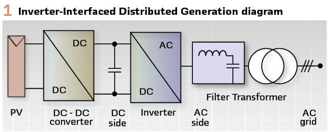
It is well established that IBRs exhibit a distinct fault response compared to synchronous generators. This is because the IBR response during a fault condition is influenced by both the physical components and the inverter control systems, particularly the LCL filter at the inverter output and the fault response control system (Figure 1). In this regard, an IIDG responds to a short-circuit fault by providing a current with limited amplitude and time-varying distorted waveforms.
The fast dynamic response of an IBR is strongly connected to the inner current control used, which can be categorized into three categories: (a) constant current source control technique (static model), (b) current control enabled with positive sequence injection during fault conditions (conventional model), and (c) the advanced current control technique considering both positive and negative sequence current injection during the asymmetrical fault condition.
- Constant Current Injection Control Technique
This is the oldest current control used in IBRs during fault conditions. The fast dynamic response this control provides during a fault condition does not meet the short-circuit or fault-response requirements as defined by international standards.
This current control technique is based on arbitrarily limiting the current output without exceeding the maximum current the inverter can withstand (|IIBR|<Imax); as a consequence, this control is unable to provide dynamic voltage support to the grid during faults.
Using this control technique, IBRs are typically equipped with a disconnection scheme to handle faults. This scheme disconnects the IBR from the faulty grid almost instantaneously. The disconnection time is generally less than one cycle (at the rated frequency) after the short circuit occurs.
Since this control technique does not comply with the fault response guidelines in the standards for both voltage support and current limitation, it is not recommended for consideration in protection studies. Therefore, it is not considered for analysis in this research paper.
However, the literature emphasizes the importance of adequately modelling the IBR control, including dynamic current limiters, to foresee and properly manage protection blindness scenarios in distribution networks. It is concluded that using simplified inverter models may lead to incorrect overcurrent relay settings, compromising protection device effectiveness and complicating fault detection.
- Conventional Current Control
Following the publication of IEEE Std 1547-2018, the short-circuit fault response requirements were included. The requirement demands that IBR provide dynamic voltage support by injecting reactive positive-sequence current. Moreover, they must limit the current to not exceed the maximum current the inverter can support, thereby preventing damage to its components. This current control technique provides uniform voltage support across all phases, regardless of the short-circuit type.
This current control technique is developed using a synchronous dq reference frame and incorporates two main control loops: an external voltage control on the direct current (DC) link, which provides the reference positive-sequence active current Id, and an internal control loop that ensures the measured currents follow the established references.
Under normal operating conditions, the injection of active current (Id) is prioritized; in the event of a short-circuit fault, the injection of reactive current (Iq) is prioritized.
According to the IEEE 1547-2018 standard and the German network codes VDE-AR-N 4100 and VDE-AR-N 4110, a reactive current injection (Iq) of at least 2% of the nominal current (In) is required for each percentage of voltage drop at the point of common coupling (PCC). Therefore, the current limitation is directly related to voltage support requirements, limiting the active component (Id) to prioritize the injection of the reactive current (Iq), whose maximum allowed value ranges from 1.5In to 2In.
Unlike the static inverter controller, which contemplates almost immediate disconnection, this conventional model provides voltage support for a specific time, dependent on the voltage drop at the PCC. This capability is known as FRT, and its duration varies depending on the standard or network code considered. In this sense, the implementation of this model could negatively affect the behavior of protections by altering traditional fault-current patterns over an extended period.
- Advanced Current Control
The advanced current control technique, following IEEE 2800 and the German grid codes VDE-AR-N 4100 and VDE-AR-N 4111, provides voltage support by injecting negative-sequence reactive current proportional to the variation in negative-sequence voltage at the PCC during unbalanced short circuits, while injecting positive-sequence reactive current during balanced faults. Moreover, it is characterized by injecting different amounts of current into each phase during an unbalanced fault, always ensuring that the current limitation does not exceed the maximum current supported by the converter.
Unlike conventional control, this model employs two synchronous dq reference frames, one for the positive sequence and another for the negative sequence. Under normal conditions, it follows the same strategy as conventional control. However, during a fault, the aim is to inject reactive currents in both sequences.
The generation of reference currents follows a hierarchy of priorities and limits. In this control scheme, the highest priority is given to injecting negative-sequence reactive current to limit fault current. This means the negative sequence reactive reference current can reach the maximum limit the inverter can support (1.5In). If the injected negative sequence reactive current (Iq2) is less than this maximum limit, the remaining capacity is allocated to establish the current limit for the injection of positive sequence reactive current and, subsequently, to define the positive sequence active current. Additionally, this model assumes that the IIDGs can inject negative-sequence current with an angular difference between the voltage and negative-sequence current of approximately 90° to 100°.
Test System
- Test System: European Medium Voltage CIGRE Network
The European medium voltage (MW) CIGRE distribution network is used in this paper for simulation purposes. This network offers versatility for studies on the integration of IIDGs, allowing the use of any of its feeders, individually or in combination, for these studies. The test system is shown in Figure2. This balanced network consists of two three-phase distribution feeders with a radial configuration. Each feeder operates at 20 kV and is independently powered through transformers from the 110 kV sub-transmission network, with a fundamental frequency of 50 Hz.
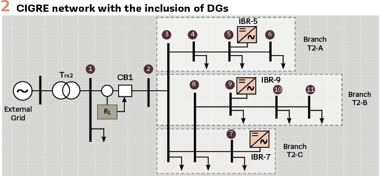
Regarding the locations and powers of the IIDGs, the CIGRE benchmark proposes placing them on feeder 2 and specifying their powers in Table 1.
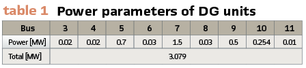
For the creation of the database of current signals to be analyzed, the generators of maximum generation, which are connected at nodes 5, 7, and 9 with powers of 0.7 MW, 1.5 MW, and 0.5 MW, respectively, as shown in Figure 2, reach an IIDG penetration level of 50%.
- Inverter Interface-based DG Model (IIDG)
This section outlines the methodology for implementing the IIDG model in MATLAB Simulink, adhering to international standards and network codes for its connection in distribution networks. The IIDG model includes a three-level Voltage Source Converter (VSC) and an LCL-type output filter. The interconnection between the IIDG and the AC network is made through a delta-star step-up transformer, as illustrated in Figure 1. The inverter control requires current and voltage data at the Common Coupling Point (PCC), including phase voltages Va, Vb, Vc, and line currents Ia, Ib, Ic that the IIDG injects into the network. The L and C components represent the inductance and capacitance of the output filter, respectively. As mentioned in previous chapters, the grid-following inverter control model is based on an advanced fault response approach that injects positive and negative sequence currents during fault conditions.
Simulation and Results
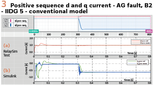
This section presents the IIDG modelling results, including the injection of positive‑ and negative‑sequence currents during faults. The purpose is to show how the inverter responds to unbalanced faults by injecting different current levels for each affected phase. It also demonstrates that the advanced inverter model can inject negative‑sequence current, while the traditional model cannot. Although several fault types were simulated, the figures focus on a single‑phase fault at bus B2, initiated at 0.307 seconds and lasting 0.8 seconds.
- Case 1: Comparative Analysis of Positive and Negative Sequence d-q Currents for Conventional and Advanced Inverter Models in RelaySimTest and Simulink
Based on the voltages measured at the PCC of both positive and negative sequences, reference currents for both fault response control models are subsequently established, and a PI controller is used to ensure that the currents in the dq frame follow these references. Figures 4 and 5 illustrate the reference and measured Id and Iq currents for the positive and negative sequence components under the advanced control scheme. It is evident that during asymmetric faults (single-phase AG), a negative sequence reactive current, Iq, is injected, simultaneously limiting the injection of active current, Id.
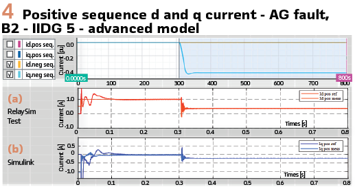
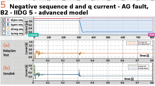
Additionally, it is observed that for unbalanced faults, the Id and Iq currents of the positive sequence are limited to give preference to the injection of negative sequence Iq, as implemented in the Simulink model. In contrast, when simulating fault response with the traditional positive sequence control model, as shown in Figure 3 (a) and (b), only positive sequence current is injected regardless of the type of fault-balanced or unbalanced-only.
Simulations conducted with RelaySimTest and Simulink, shown in Figure 3a and 3b, demonstrate that in the conventional model, the injection of positive sequence reactive current q remains approximately 0.6 pu, and the active current d of the positive sequence is limited, in line with the priority given to reactive current in both software systems.
On the other hand, in the advanced fault response model of the inverter, the positive sequence d and q currents exhibit variations between the two software systems due to differences in priorities set by the IEEE 2800 and VDE-AR-N 4100 standards, which allow varied operations based on the priority of active and reactive current. Three main components are identified: Id1, Iq1, and (Id2 and Iq2), with three possible priority schemes: a three-priority mode, a two-priority mode, and an equivalent-priority mode.
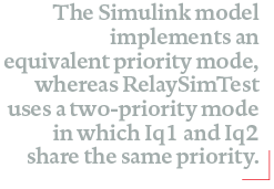
The design of the current limiter varies according to the chosen priority mode. The Simulink model implements an equivalent priority mode, whereas RelaySimTest uses a two-priority mode in which Iq1 and Iq2 share the same priority. Suppose the sum of the reactive components is less than the maximum allowed current. In that case, the surplus is injected into the active current Id1, thereby justifying the observed differences in Id and Iq currents between the two software systems. (Figures 4, 5).
- Case 2: Head-End Relay EMT Current Signal Comparison for Conventional and Advanced Models across RelaySimTest and Simulink
This section compares the current electromagnetic transient (EMT) signals observed by the head-end relay for both models in RelaySimTest and Simulink, as illustrated in Figure 6 a and 6 b. The results from the traditional model show a 1:1 correlation with the simulations in both software systems.
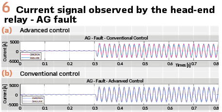
On the other hand, in the advanced model (Figure 6 b), it is verified that the IIDG fault responses in RelaySimTest and Simulink are consistent in phase and exhibit approximately the same current amplitudes. However, differences in amplitudes are due to the priority modes in current limiting, as discussed in subsection A. The highest current amplitude observed in RelaySimTest is 3512A, while in Simulink it is 3350 A, resulting in a relative error of 4.28% when RelaySimTest is used as the reference. This discrepancy highlights the need to standardize the priority modes for current limits in future studies to minimize these differences.
Conclusions
From these analyses, it is clear that protection blinding scenarios can intensify during unbalanced faults when only the conventional positive-sequence injection model is used. To ensure that a truly advanced and standardized fault response model is designed and can adequately identify and mitigate protection blinding, precise modelling of the inverter is essential. This includes fault response control of the inverter, involving the injection of both positive and negative sequence currents, which is crucial for accurately identifying and anticipating protection blinding scenarios in a distribution network. Therefore, the development of protection schemes must progress in tandem with the updating and standardization of these models.
Using a static inverter model, no cases of protection blinding are detected; however, with advanced models, these cases become apparent and can be adequately identified and mitigated. It is crucial to accurately model the current limiter during fault analyses to protect the network against potential protection blinding events, which can vary in visibility depending on the inverter model used.
Moreover, protection blinding scenarios can intensify in situations of unbalanced faults if the inverter is modelled with only positive sequence injections. Therefore, to design a protection scheme that is truly aligned with the standardization of fault response models and that ensures adequate detection and mitigation of protection blinding, precise modelling of the inverter is essential, including the dynamic injection of both positive and negative sequence currents. Additionally, failing to consider the standardized inverter model and the angular difference between the voltage and negative-sequence current requirements imposed by standards hinders the effective use of directional elements, exacerbating challenges such as sympathetic tripping and bidirectional flows. Consequently, the development of protection schemes must proceed in parallel with the updating and standardization of inverter models.
In this regard, the evolution of protection schemes for fault detection in electrical networks must align with the functional requirements of emerging standards. As mentioned, these regulations and standards require that new distributed generation units be capable of supporting network voltage by injecting both positive- and negative-sequence currents during fault conditions. The conventional control scheme, which does not account for the injection of negative-sequence current during unbalanced faults, can lead to significant inefficiencies in detecting and determining their directionality. In contrast, controlling the negative sequence current, which manages the reactive current of negative sequence to provide voltage support, can significantly enhance the effectiveness of these directional elements.
Biographies.

Veronica Alejandra Rosero Morillo received the Ph.D. degree in electrical engineering from the Instituto de Energía Electrica, Universidad Nacional de San Juan, San Juan, Argentina. She is currently a Postdoctoral Researcher with INESC TEC—Institute for Systems and Computer Engineering, Technology and Science, Porto, Portugal. Her research interests include adaptive protection of distribution networks with high penetration of inverter-interfaced distributed generation, overcurrent protection schemes, and high-impedance fault detection using advanced signal processing techniques. She has conducted an international research stay at TU Dortmund University, Germany. Her work has been validated using real-time simulation platforms such as OPAL-RT and Typhoon HIL and published in peer-reviewed international journals and IEEE conferences.
Francisco M. Gonzalez-Longatt is Founder and leader of the DIgEnSys-Lab (Digital Energy Systems Laboratory) at the Department of Electrical Engineering, Information Technology and Cybernetics, University of South-Eastern Norway, Norway; He is currently with the Centre for Renewable Energy Systems Technology (CREST) at Loughborough, University in the United Kingdom. His main area of interest is empowering the secure and resilient operation of energy systems by taking advantages of the digital technologies.

Joao Jorge is an Electrical Engineer, specialist in Power Systems Protection, Control, Communication, Automation & Testing Solutions, acting as IEC 61850 Regional Application Specialist for OMICRON Electronics Latinoamerica; has a postgraduate degree in Electrical Systems Protection and is pursuing a postgraduate degree on Cyber Security. Active member of Cigre Brazil Study Committee B5.

Ana Garcia graduated in 2012 with a degree in Industrial Engineering, specializing in Electrical Engineering, from Universidad Politécnica de Madrid. She began her career in Klaus, Austria, providing technical support for OMICRON’s solutions in protection, control, and measurement systems. Since 2017, Ana has been working as an Application Engineer at OMICRON’s Madrid office, focusing on delivering expert technical support, training, and application solutions for power systems testing technologies.

Andre F. S. Melo is a Global System Architect at Digital Power Application Center (DPAC) of Schneider Electric. He received the BSc degree in Computer Engineering from Universidade Potiguar (UnP) in 2017 and the MSc. degree in Electrical Engineering from Universidade Tecnologica Federal do Paraná (UTFPR) in 2021. He is now pursuing Ph.D. degree in Power Systems at Universidad de Sevilla. His fields of interest include Protection and Control System, Digital Substations, and IEC 61850. Mr. André is an IEEE Senior Member and an active member in various work groups of IEC TC57, CIGRE B5, and IEEE PES PSRC & PSCCC.