and establishment of design policy for process bus application system
By S. Sakai, K. Kojima and Y. Ito, Chubu Electric Power Grid Co.,Inc, Y. Kurose and S. Iida, Toshiba Energy Systems & Solutions Corp., Y. Ito and M. Sugiura, C-Tech Corp.
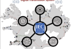
The new concept of Protection and Control System (PACS) in substations uses station bus and process bus according to the international standard IEC 61850 to digitalize the information of the substation. In particular, the application of process bus can significantly reduce costs and cables compared to the implementation of simple station bus compliant with IEC 61850. Recently, a process bus based PACS has been proposed in Japan to streamline electric power facilities and utilize data. Practical research and developments for the process bus based PACS in Japan were introduced in the Electric Technology Research Association report and demonstrations, e.g. paper.
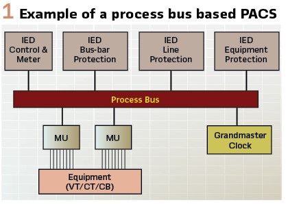
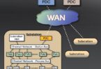
Figure 1 outlines a process bus based PACS. Each Intelligent Electronic Device (IED) realizes appropriate protection, control and measurement functions with AC voltage and current data sampled by each Merging Unit (MU). Although various vendors manufacture these devices, interoperability is ensured by complying with IEC 61850.
The interoperability is important since interoperability is expected to benefit a significant reduction of control cables through optical data communication between devices and a reduction of procurement risk through multiple vendor sourcing. On the other hand, multiple IEDs installed at the bay level are installed for each purpose of use, such as line protection, electric power equipment protection, and control functions, to construct a system.
In order to further reduce costs and streamline electric power facilities, it is necessary to consider the integration of protection and control functions.
In addition, when applying a protection control system composed of process bus to Japan, it is necessary to consider specifications that are unique to Japan. The standard protection relay system in Japan is required to implement a reliable false tripping prevention function, from the viewpoint of reliability of power system operation. Even in a process bus based PACS, it is necessary to define detailed specifications for false tripping prevention in order to realize highly reliable protection relay systems.
In this article, we propose a new process bus based PACS that conforms to the Japanese specifications and integrates protection & control functions, and present the results of a multi- vendor connection verification.
Points of issue
This article proposes a new process bus based PACS as a solution to the following problem:
1) High costs associated with system implementation: Generally, IEDs installed at the bay level are divided into separate devices for each function to be implemented. Separating the devices reduces the risk of loss of functionality, but the installation cost is high.
2) Consideration of system redundancy by function integration: If devices with integrated functions are used, the impact of a device failure is significant. When applying an integrated system, it is necessary to consider system redundancy.
3) Application to Japanese standard specifications: In Japan, there is a demand for high reliability in grid operation. This high reliability cannot be achieved only with general IEDs. It is necessary to organize a robust protective relay system configuration with a function to prevent false tripping.
4) Need for multi-vendor verification: If supply from multiple vendors becomes possible, a replacement will be possible even when discontinued models break down. For multi-vendor connections, it is necessary to verify interoperability considering optional elements not defined in IEC 61850 and IEC 61869.
Solutions
Functional integration and redundant systems: In conventional PACS, electric power equipment and protection/control devices are connected by copper cables, and due to the limited processing power of CPUs, distributed systems with one function per device were common. The systems are characterized by the following three points:
1) Low protection program computation load per device
2) Little influence in case of partial failure, and
3) Easy increase/decrease of devices due to system modification
Recently, with advances in CPU processing technology and the technological development of digital substation construction with process bus configuration based on IEC 61850, it has become possible to realize centralized protection and control (CPC) systems, which are different from the conventional PACS. The CPC systems implement protection and control functions for multiple lines in a single device.
Advantages of the systems include the following:
- The number of devices applied to the PACS can be reduced, resulting in space savings and cost reductions
- The number of physical interfaces, such as network switches can be significantly reduced
- Since the only type of device needed for PACS for the whole substation system is the CPC and MU, spares can be easily secured, and maintainability can be improved. (SCADA and GW are also available, but they are considered a separate issue having no influence on PAC.)
- Simplification of GOOSE message settings between bay levels
On the other hand, when adopting a CPC system, redundancy should be considered to ensure reliability. In a distributed system, if one protection device breaks down other devices can provide backup protection. However, if a CPC device is used, the influence of a failure is more significant because one device has all protection and control functions for multiple lines.
The Intelligent Merging Unit (IMU) with integrated protection functions in place of the MU enables risk diversification in the event of failure. Since the protection function of an IMU is limited, long-term operation is not desirable. However, by employing an IMU, electric power equipment damage by overcurrent can be avoided.
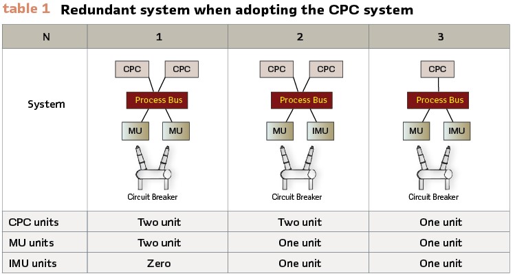
Table 1 describes the redundant system when adopting the CPC system:
- No. 1 case has two CPC devices for the entire system and two MUs for each line to be protected. If one MU fails, the other MU forms a bypass circuit to provide protection. The system is able to cope with the failure of one device but not the failure of two CPC devices and a communication breakdown between the CPC and the MU
- No. 2 case has one MU and one IMU installed on each line. The IMU has a backup protection function for the CPC, as described above. The IMU activates backup protection when it receives information from two CPCs, such as device failure and communication break down
- No. 3 case does not lose protection even if one of the CPC devices, MU, or IMU fails. This system can realize inexpensive system construction because the number of devices can be reduced as much as possible.
However, if a single CPC unit fails, it will not be possible to implement a legitimate protection system or to monitor and control equipment at the control center.
Therefore, it is desirable to restore the CPC device as soon as possible.
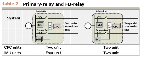
It is conceivable to reduce the number of MU to reduce costs further. If there is only one MU for the target line to be protected, the protection function will be lost in the event of MU failure, but for two parallel transmission lines, as shown in Table 2, there can be only one MU for the target line to be protected. Two parallel transmission lines are common in Japan, so this configuration can be easily adopted. The detailed circuit is shown below.
Characteristics of Protection Relay Systems in Japan: A protective relay device must not operate incorrectly during normal power system operation but is required to operate properly when a fault or abnormal condition occurs. Therefore, if the device operates unintentionally, the value of the device is completely lost. Protection relay devices in Japan adopt an “AND” configuration with “primary protection relay (Primary-relay) and fault detecting relay (FD-relay)” to minimize the unwanted protection operations, as shown in Figure 2.
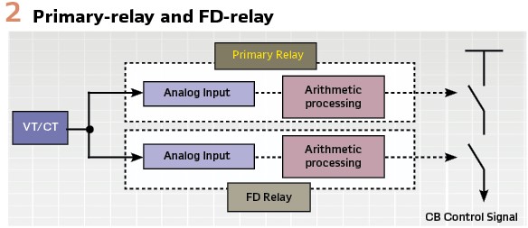
The AND configuration prevents unwanted operation due to the failure of a single part or human error. Primary-relay and FD-relay have independent hardware, and the output contacts from both relays are connected in series. We design the FD-relay element not to unintentionally operate both the FD-relay and Primary-relay in case of a single VT/CT failure.
A general IED consists of 1CPU and cannot be separated like Primary-relay and FD-relay.
In the process bus-based protection relay system in Japan, it is necessary to ensure the same reliability as the conventional protection relay system.
Therefore, when adopting general IEDs, it is necessary to configure Primary-relay and FD-relay with multiple IEDs.
Systems employing CPC devices have been considered in the past. A new high reliability process bus based PACS with the AND configuration is proposed in Figure 3, employing a CPC device.
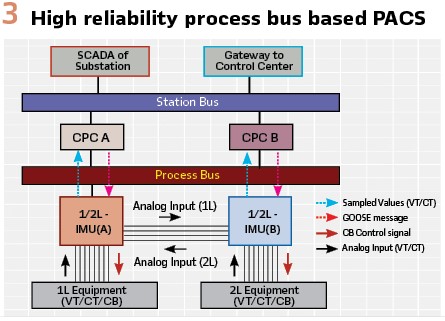
Two CPC devices shall be installed, and one IMU shall be installed on each line with two parallel transmission lines. This configuration consists of two CPC devices to avoid loss of monitoring and control when one device has failed. The CPC device and IMU are compatible with the Parallel Redundancy Protocol (PRP: IEC 62439-3) to ensure communication line redundancy and improve operational continuity. The functions integrated into the CPC device are transmission line protection, bus-bar protection, transformer protection, and control and measurement functions for all lines in a substation. Sampled value (SV) data is continuously acquired from the IMU, and protection control algorithms are executed. In the event of a fault, each IMU on each line receives a GOOSE message from the CPC and operates a contact output. The target line is tripped when both contacts are closed. Figure 4 shows the trip circuit.
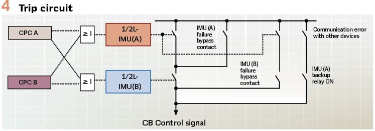
As an example, the case of a fault on a No.1 transmission line (1L) is shown. Two CPC devices acquire SV data from the IMUs. Each CPC device sends a GOOSE message to the 1L-IMU and No.2 transmission line (2L)-IMU when detecting the fault.
Each IMU closes its contact, then the Circuit-breaker (CB) for the 1L is tripped. This circuit has a function to prevent unwanted protection operation due to a single component failure or human error, as required in Japan. In addition, when one IMU fails, a bypass circuit is configured to enable fallback function operation.
This is a configuration that can provide protection even if the IMU of the target line is disconnected from all devices due to a communication error. The IMU is equipped with a backup relay (ΔOC) to detect abnormal currents and provide protection before electric power equipment damage occurs. This system is robust.
Interoperability Testing:
Mutual Data Setup: The CPC, IMU, and each ICT (IED Configuration Tool) employed in this verification are based on IEC 61850.
The CID files of the CPC and IMU created by each ICT were exchanged in advance, and the settings of GOOSE Subscribe and Sampled Value Subscribe were implemented in advance.
In addition, prior to connecting to the actual electric power equipment, GOOSE Subscribe was verified in advance by simulating the transmission data using the CID file. It was confirmed that the data could be received as configured.
Because of the pre-configuration and pre-verification in the simulation, the interconnection between the CPC and the IMU on the actual device was successfully performed without any problems.
Time Synchronization between each device is essential to implement PACS in a substation. Synchronous sampling between each MU is necessary for protection systems using multiple MU data, such as current differential protection relays. A typical effective synchronization method is the IEEE 1588 PTP (Precision Time Protocol), which uses the transparent clock functions of network switches and the Grand Master Clock (GMC). This synchronization system would be managed by a GMC in the substation. If this synchronization system cannot comply with the reliability requirements of PACS, some redundant configuration is necessary. PTP time synchronization compensates for clock offset and transmission delay by exchanging timestamped messages between the master and slaves.
There are two operational modes for sending timestamps: In one-step mode, a time stamp is embedded in the Sync message. In two-step mode, a Follow Up message with an embedded timestamp is sent after the Sync message. In substation PACS, time synchronization is performed by connecting slave devices, such as IEDs and MUs, to the GMC via a network switch. When synchronizing devices, aligning the operational mode settings between the devices is necessary. Receiver (slave) devices such as IEDs and MUs support both One-step and Two-step modes, but transmitter (master) devices may support only either One-step or Two-step modes. When multiple GMCs are installed for redundancy and IEDs or MUs are fixedly operated as slaves, time synchronization is possible regardless of which operational mode the GMC or network switch is set to, and no problems arise. However, if only one GMC is installed and that device fails, a master clock will be provided by one of the IEDs and MUs in slave mode. If the device that becomes the next master does not support the operational mode used in the GMC or network switch, time synchronization will not be possible. Protection systems that use multiple MU data, such as current-differential protection relays, may operate unintentionally if time synchronization between devices is impossible. When constructing a process bus based PACS, it is necessary to consider the operational mode of the transmitter device supported by the device that can become the master. It is important to determine in advance the detailed operational mode and master priority of the GMC, network switches, and other devices.
Verification Test
Test case: The test scenario is based on the image of actual bus-bar protection in a substation. The protection system uses current differential protection relays as the main protection. The relay is highly vendor-dependent and should be verified when the IMU is used by different vendors.
The ratings and setting values are as follows:
- System frequency: 60 Hz
- Secondary system rating: current = 5 A, voltage = 100/√3 V
- Sampling frequency and SV data communication update frequency: 4800
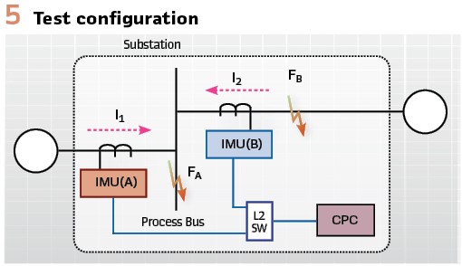
To verify the performance of the CPC system, the authors configured two IMUs, one CPC, and network switches as shown in Figure 5. Each IMU is configured by a different vendor.
The main test items are as follows:
1) Current differential relay performance test: The performance of CPC’s differential protection relays shall be evaluated using existing relay test methods. Test results shall be equivalent to those of existing relays.
The effects of synchronization errors shall also be checked.
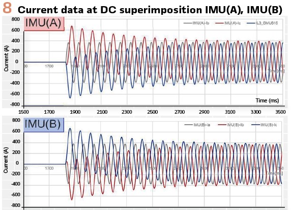
2) Transient test: Evaluate the absence of unwanted protection operation when a lightning fault occurs and a DC current is superimposed. Also, it is evaluated that there is no unnecessary operation when the CT is saturated by a fault at the device’s closest end. The results must be equivalent to those of existing relays.
Test results:
Protection control function test: (Figure 6).
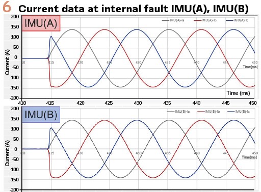
In case of internal fault (Fault point : FA) . . . Positive operation
In case of external fault (Fault point : FB) . . . Positive non-operation
Transient phenomena test: (Figure 7).
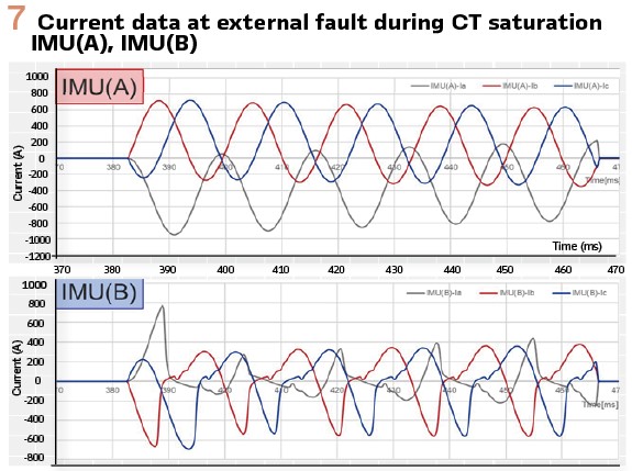
In case of internal fault during CT saturation (Fault point : FA) . . .Positive operation
In case of external fault during CT saturation (Fault point : FB) . . . Positive non-operation
In case of superimposed DC current . . . Positive non-operation.
Conclusion
This article presented a new process bus application system configuration built by multi vendors, which has very high reliability in power system operation, using devices with integrated protection and control functions.
Also, we introduced the usefulness of the process bus application system equipped with a Malfunction prevention system that has been adopted as a standard in Japan, and that it is equivalent to the existing system.
This shows that the system is a robust protection system against undesirable events on power systems.
Based on the results of this article, the authors will adopt the process bus based PACS and contribute to the spread of resilient power systems.
To this end, the authors will continue to conduct long-term continuous operation tests, expand the application of the system to various PAC applications, and improve its availability, reliability, and compatibility with existing PACS. We will trial the introduced process bus system in a 77 kV substation in 2024 and plan to adopt it as standard in the future.
Biographies:
Shotaro Sakai received a Master of Molecular Design and Engineering from Nagoya University in March 2016. He belongs to Chubu Electric Power Grid, one of the electric power transmission and distribution companies in Japan. Since 2016, he is responsible for the application of IEC 61850 and the realization of digital substations and is studying the technical specifications of protection and control systems. He was engaged in substation PAC system maintenance and construction work for about 5 years.
Kazuhiro Kojima received the BS and MS degrees in electrical engineering from Tokyo Metropolitan University.
Since 1999, he has been working with the Chubu Electric Power Grid Co., Inc. His research interests include protection and control of power systems, the application of IEC 61850, and the realization of digital substations.
Yuki Ito received the BS degrees from Nagoya Institute of Technology in 2008.
Since 2008, he has been working with the Chubu Electric Power Grid Co., Inc. His research interests include protection and control of power systems, the application of IEC 61850, and the realization of digital substations.
Yuta Kurose received a Master of Engineering from Tokyo Institute of Technology in 2016.
Since then, he has been working at TOSHIBA Energy Systems & Solutions, where he is responsible for engineering for protection and control systems.
Shingo Iida received a Master of Computer Science and Engineering from Nagoya Institute of Technology in 2007. Since then, he has been working at TOSHIBA Energy Systems & Solutions, where he is responsible for software development for components of protection and control systems. His areas of interest include firmware technology, digital substation systems, and IEC 61850 applications.
Yuichi Ito graduated from Yokkaichi Technical High School. He joined Chubu Electric Power in April of the same year and was engaged in substation PAC system maintenance and construction work for about 22 years. He was seconded to C-TECH in April 2021 and is engaged in the development of protection and control devices related to IEC 61850.
Mitsutoshi Sugiura received his master’s degree from Nagoya Institute of Technology in March 2016. He joined Chubu Electric Power (currently Chubu Electric Power Grid) in April of the same year and was engaged in substation PAC system maintenance and construction work for about 4 years. He was seconded to C-TECH in October 2020 and is engaged in the development of protection and control devices related to IEC 61850.