by P. Mohapatra, SP Energy Networks, UK, C. Popescu, ABB, UK, P. Balasubramani, GE, UK, M. Wehinger and Ali Abdulla, OMICRON electronics
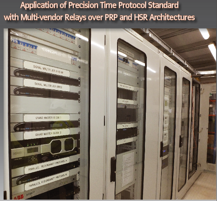
The project called FITNESS (Future Intelligent Transmission Network Substation) is set to be the first multi-vendor digital substation and automation system in the UK led by Scottish transmission network owner SP Energy Networks. It encompasses two circuits covering protection, control and monitoring of the local substation as well as protection at the remote end.
The equipment will be deployed at Wishaw 275 kV substation in Scotland. It is the first IEC 61850 multivendor based system with equipment from GE Grid Solutions, ABB Ltd, Synaptec and testing tools from OMICRON electronics.
In the FITNESS project, the innovation is to be found in the way the overall system has been designed in order to prove interoperability – a mixture of protection and control equipment from various manufacturers – at process and station bus, as well as Substation Control System (SCS). This project will enable SP Energy Networks to prove not only interoperability at multiple levels but also within a mixture of old and new technologies. The proposed FITNESS architecture introduces the IEC 61850-9-3 (Power Utility Automation Profile) Precision Time Protocol (PTP) with the two redundancy methods in the communication architecture – the Parallel Redundancy Protocol (PRP) and the High-availability Seamless Redundancy (HSR).
Time synchronization is of paramount importance for maintaining reliability and availability of the process bus and sampled values and consequently, the availability of critical protection and control functions in a digital substation. Depending on the regulations, utilities may not accept loss of protection functionalities for more than 1-3 secs, and such loss cannot be a frequent occurrence. In the FITNESS project time synchronization is achieved predominantly by application of the IEC 61850-9-3 standard. This part of the IEC 61850 standard specifies a PTP power utility automation profile of IEC 61588:2009 | IEEE Std 1588-2008 applicable to power utility automation, which allows compliance with the highest synchronization classes of IEC 61850-5 and IEC 61869-9. There is also application of pulse per second (pps) in FITNESS for one merging unit (derived from a PTP compliant IED) and Simple Network Time Protocol (SNTP) for SCADA systems. This article focuses on the application and testing of PTP in the FITNESS digital substation solution.
In a typical digital substation application, the most demanding network in terms of time synchronization is the process bus level where accuracies as low as 1 microsecond are required to meet the adequate accuracy level for sampled values. Going up in the hierarchy of the substation automation systems (SAS), the bay level requires accuracies in the range of milliseconds and the station in the range of tens/hundreds of milliseconds. Like other important areas within SAS, time synchronization has developed over the years from a standalone system using its own time synch infrastructure to time synch sources that send the clock signal directly over the Ethernet network. By doing so, a significant reduction of the time synch cabling is expected.
Standards Implemented
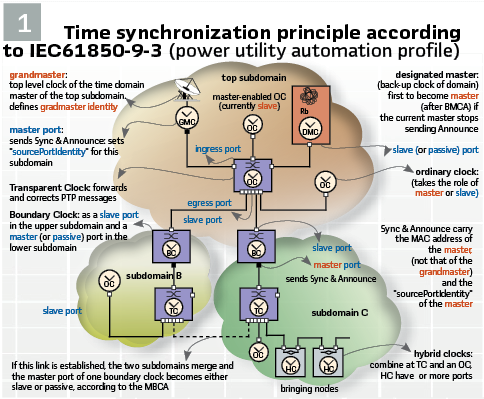
The proposed architecture for FITNESS project uses the IEC 61850-9-3 PTP- power utility profile. In PTP networks there must be only one recognized active clock at a time, called the Grand Master Clock. If there are two Grand Master Clocks on the network (as it is the case in FITNESS project) then a Best Master Clock Algorithm (BMCA) is required in order to ensure that all client devices will synchronize to the same Grand Master Clock. The other Grand Master Clock that is not detected / selected as Grand Master Clock (GMC) will stop sending the synchronization packets itself and will accept the synchronization from the Best Grand Master Clock (BGMC). (see Figure 1).
All components play a big role in a PTP network and directly influence the level of accuracy that can be achieved by the clients. Asymmetric network connections degrade the accuracy, therefore classic layer 2 and 3 Ethernet switches with their “store and forward” technology are not suitable for PTP networks and should be avoided.
PTP synchronization is LAN (Layer 2 Ethernet Mapping) based, multicast addressing using peer-to-peer delay measurement. An important requirement for PTP based systems is that switches (at both station and process bus levels) and IEDs must be able to act as Transparent Clocks (TC) and as Boundary Clock (BC) respectively.
A Transparent Clock (TC) is capable of measuring the time taken by a PTP message from the ingress port to the egress port and to add the measured time value to a correction cell in the message. In this way, any delays/asymmetry that the device could introduce in the transfer of PTP messages are corrected. Network switches belong to this category of Transparent Clocks. A TC shall introduce less than 50 ns of time inaccuracy, measured between the applied synchronization messages at any ingress port and the produced synchronization messages at any egress port, provided that it is in steady state.
A Boundary Clock (BC) is a multiport device that synchronizes to the reference time provided by a master clock on one port and delivers time on one or more ports. Switches, bridges, routers and some IEDs belong to this category. A BC shall introduce less than 200 ns of time inaccuracy between the port in the SLAVE state and any port in the MASTER state, provided that it is in steady state.
An Ordinary Clock (OC) is a clock that has a single Precision Time Protocol (PTP) port in a domain and maintains the timescale used in the domain. It may serve as a source of time, i.e., be a master clock, or may synchronize to another clock, i.e., be a slave clock. IEC 62439-3 allows 2 for Ordinary Clocks that are doubly attached. When the OC is the best clock of its subdomain, it becomes the Grandmaster Clock (GMC). Its port is in the MASTER state and sends Sync messages to synchronize all slave clocks. Otherwise, its port is in the SLAVE (or PASSIVE) state and it receives synchronization messages.
Hybrid clocks (HC) combine a transparent clock (TC) and an ordinary clock (OC).
The Best Master Clock Algorithm (BMCA) is the basis of PTP functionality. The BMCA specifies how each clock on the network determines the best master clock in its subdomain of all the clocks it can see, including itself. The BMCA runs on the network continuously and quickly adjusts for changes in network topology (HSR or PRP).
The BMCA typically uses the following criteria to determine the best master clock in the subdomain:
- Priority assigned to the clock (1 and 2) by the user
- Clock Class: Global when synced to a satellite, Local synced with local oscillator and other states for other levels of holdover
- Clock’s accuracy to UTC
- Clock variance dependent on the clock’s oscillator stability
- Unique Identifier: MAC-Address-based selection
In addition to identifying the best master clock, the BMCA also ensures that clock conflicts do not occur on the PTP network by ensuring that:
- Clocks do not have to negotiate with one another
- Master clock identification process ensures no two master clocks or no master clocks
FITNESS Architecture
In the FITNESS project, the time synchronization architecture comprises of two multi-vendor GPS based Master Clocks (GE and Meinberg), acting as Grand Master Clocks, directly connected to the two station LAN switches on PRP, configured to act as Transparent Clocks. From station level, the clock signal is transferred to the bay level switches, configured as Boundary Clocks. These devices participate in selecting the best master clock and can act as the master clock if no better clocks are detected. The boundary clock mitigates the number of network hops and results in packet delay variations in the packet network between the Grand Master and Slave. This enables the synchronization of SCUs & Merging units present in the process level.
In order to ensure availability and reliability of the time synchronization throughout the architecture,
1. Both GE & ABB GMC acquire time from GPS & GLONASS
2. Both the GMC are connected on PRP
The combined architecture for FITNESS project has been updated to classify the Boundary clock (BC) and transparent clock (TC) respectively based on the following:
1. The H49 units used for the Interlinks, marked “IL-GE” on the drawing should be a BC as per the recommendation for a PRP/HSR interface in the IEC 62439-3 standard. When there is any topological change in architecture
2. Rest all IEDs/switches/Redbox can be a TC
3. Process Level switches at Newarthill circuit 1 “NS-ABB (PB1)” and “NS-ABB (PB2)” in Circuit 2 should certainly both be TC, as they are connected directly to grandmaster clocks.
4. Bay level switches at Newarthill circuit 1(PRP ‘A’) and (PRP ‘B’)” could be either BC or TC. However, it is recommended that they are TCs, as this means that the other switches and IEDs below in the PRP network of Circuit 1 will get their sync directly from the grandmaster and this will facilitate the accuracy. The argument for using BC here is that it would reduce the multicast traffic on the PRP network, but in this small network it is not a significant gain. (Figure 2)
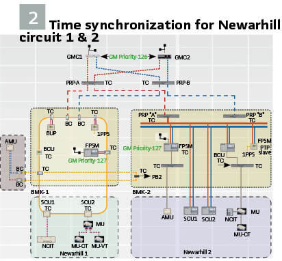
5. While connecting a RedBox (HSR/PRP) to a single attached node (SAN), then the recommendation is to configure it as a TC
Test Setup and Methodology
In the FITNESS set up as discussed in the previous section multi-vendor grand master clocks are connected at the station level. The clock signal is distributed to the bay level switches and IEDs. These devices participate in selecting the best master clock and could act as master clocks if no better clocks are detected. Once synchronized, the merging units can provide multiple time synchronization signal outputs in pulse per second (PPS) format, as this may be required by some devices that are not yet compatible with IEC61850-9-3 PTP time synchronization protocol.
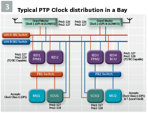
In the test set up both the Grandmaster clocks are synchronized via GPS / GLONASS and were set to the same priority sets, that is same parentDS. Grandmaster Priority1 & parentDS.Grandmaster Priority2. The best GM (highest priority and accuracy) became the Grandmaster. The successful synchronization of all devices could be checked by analyzing the network traffic using tools as discussed below and checking the synchronization status of individual devices (switches and IEDs). Once all devices were configured and connected according to Figure3 (representative of one of FITNESS bays), a series of test cases are required to be run in order to demonstrate time synchronization under certain conditions.
The test set-up network traffic was monitored using tools with PTP sniffers such as Meinberg PTP Track Hound and Omicron’s DANEO 400. The DANEO in addition to the network also monitored individual IED data streams and SVs synchronization statuses. It was also used to detect abnormalities in the network traffic and automatically logs all events with the corresponding detailed information (e.g. lost samples, GOOSE timing problems, PTP time synchronization issues, etc.).
As logging the sync status from the IEDs gives limited information on the time synchronization quality. Additionally, IEDs with PPS outputs and – ideally – an independent GPS clock can be used to compare the PPS signals at different points in the time distribution hierarchy to confirm the complete time synchronization status across different points of the network.
Overall System Tests: The tests to prove the robustness of the time synchronization architecture were:
- Tests under loss of satellite signals (GPS and GLONASS)
- Tests under loss of LAN A or B in PRP and Direction A or B in HSR rings in the redundant networks
- Tests under loss of one or both GMCs and operation of network where one of the BCs takes over as the GMC
Process Level Tests: In FITNESS the process level as mentioned above was considered most critical in terms of time synchronization availability and reliability requirements. Therefore, extra process level tests were performed to ensure stability of Sampled Values streams under different synchronization conditions. At the process level, both Merging Units are configured to publish data streams according to the 9-2LE implementation guideline. At station level, IEDs were configured to subscribe to the Sample Values generated by the Merging Units as represented in Figure 3 for one of the bays.
In preparation for process level tests, all IEDs and Merging units were properly configured as subscribers and publishers, respectively and time synchronization status of individual IED was checked. The SmpSync field denotes the synchronization status of the sampled value stream. According to IEC 61850 the possible values of SmpSync are:
- 0 – SV stream is not synchronized by an external clock signal
- 1 – SV stream is synchronized by a clock signal from an unspecified local area clock
- 2 – SV stream is synchronized by a global area clock signal (time traceable, GPS)
The following tests were performed at process bus level:
- The disconnection and reconnection of the Merging Unit from the network to ensure that the Merging Units resume publishing SVs to IEDs with synchronized status SmpSync 1 or 2 (provided the overall communication network has valid PTP stream available synced to a GMC)
- Disconnection and Reconnection of time synchronization signal to the Merging Unit or the communication network. The publishing merging unit should go into holdover mode and continue to publish Sampled Values with SmpSync =1or 2 for until the holdover duration is exceeded. The minimum holdover duration shall be 5 s under stable temperature conditions. Upon reconnection of time synchronization signal within the holdover period the Merging Unit should continue publishing Sampled Values with SmpSync=1or 2 that is good synchronization quality
Observations: The following observations were made based on testing of the best master clock algorithm through selection procedure based on:
Option 1 Selection of MC based on clock class: If both MCs are unavailable (two simultaneous failures), the system still runs within the specified accuracy (250ns) with PTP time synchronization provided by the BC, a GPS based unit protection which is a master capable clock. This means that all devices in the network are synchronized from this clock (class 6). In the event of the BC clock failure (a 3rd failure), the system runs on the most accurate local oscillator (clock class 7). This is observed when the MC and BC are given the same priority.
Option 2 Selection of MC based on priority and then clock class: In subsequent tests it was observed that by giving the BC a lower priority (higher in number) it can be eliminated from the Best Grand Master Clock (BGMC) algorithm if any of the MCs are on the networks and have a better accuracy on oscillator mode (clock class 7). This option was considered after we observed that even the slightest mismatch in settings for the power profile such as that of holdover times between multi-vendor clocks caused a delay of 15-30 secs in the selection of the BGMC. Thus, assigning the clock with a better oscillator preferred priority in a multi-vendor BGMC application such as in the case of FITNESS, improves the time required for the selection process for the BGMC algorithm.
In FITNESS option 2 is the preferred method as typically, a good local oscillator can maintain the accuracy within 1 microsecond for more than 12 hours – a performance comparable to an atomic clock. This increases the overall protection scheme availability under non-GPS and non-GLONASS condition and eliminates BC from the 1st selection iteration thus improving performance.
Once all devices have been configured and connected according to Figure 1, a series of test cases were run to demonstrate time synchronization under the following conditions:
- Clocks change over whilst in GPS mode (class 6)
- Clocks change over whilst in holdover mode (Clock class 7 – system running on local oscillator)
- Clocks availability during LANs failure combined with loss of one or both GM clocks
The observed behavior of the system was as follows:
- The best-known clock on the system became the Best Grand Master Clock (BGMC)
- The other MC clock went into passive mode
- All devices (IEDs, switches and Merging Unit) had the same time as the BGMC
- All (IEDs, switches and Merging Units) shown a synch locked indication
- All IEDs, switches and Merging Units) shown the Grandmaster identity (the same BGMC)
- When the current grandmaster clock went down, the passive clock was elected and became the new grandmaster
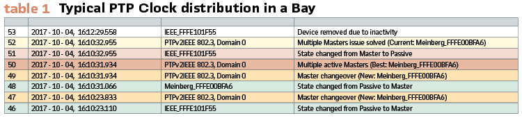
The behavior of the overall system was in line with the IEC 61850-9-3 standard – the switching between the two Grand Master Clocks was seamless under both test scenarios (GPS and non-GPS conditions). The Merging Units – the most demanding device when it comes to PTP synchronization – exhibited a much better holdover time than the one specified in the standard (minimum 5 sec). This allowed for detection of abnormalities in the network traffic and to automatically log all events with the corresponding detailed information. (see Table 1).
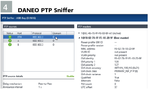
Additionally, PTP sniffer from Daneo 400 was used to display all the details of the current real-time PTP grandmaster clock. The tool additionally checked the system behavior and synchronization status of IEDs and data streams during the tests. (Figure 4).
Recommendations
It should be noted that – as in any protection related matters – it’s quite difficult to get the right balance between scheme security and availability under various Sample Value synchronization conditions. The definition in IEC 61850-9-3 for steady state as 30 s after a single master starts to send synchronization messages and 16 s after a change of master, with no change to the environment temperature, indirectly implies that MUs may not be in a steady state for 16 s during a changeover. This may not be acceptable to utilities for system critical functions. Another solution could be to increase availability of MUs, for example, vendors could allow MUs to holdover for 30 s for protection applications instead of 10 s as required for metering applications. Vendors currently tend to put a strong emphasis on scheme security – although robust enough, under certain re-synchronization conditions, the Merging Unit was blocked, and thus unable to provide Sample Values to the protection and control IEDs. On the other-hand, utilities put more emphasis on scheme availability, whilst expecting to maintain security at an acceptable level.
It was observed that even a slight mismatch in power profiles and configurations in both MCs increased the negotiation time in the best master clock algorithm. In order to avoid this both MCs were set to power utility profile and associated configurations were exactly matched and a significant improvement was observed in the performance of the best master clock algorithm. Our recommendation is to clearly specify the requirement to match the profiles in the standard.
Conclusion: In selection of GMC investment in one with a good oscillator providing a holdover period of 12-24 hours providing required accuracy levels is recommended. The next step for utilities should be the consideration of PTP time synchronization over the wide area network to provide centralized time synchronization as the primary or back up to the local clocks within the substations. The IEC 61850-9-3 standard and GMC manufacturers should work closer with utilities to enhance the standard and the clocks using user experiences especially from multi-vendor applications.
Biographies:
Priyanka Mohapatra is currently working as RIIO T2 Innovation Lead at SP Energy Networks. She is the project and technical lead for project FITNESS. Prior to joining SPEN, Priyanka was working with Siemens AG for 8 years. She started at Siemens Ltd., India as an electrical engineer before moving to Siemens AG Global R&D, Germany and with Siemens Protection Devices Ltd., UK as a product owner and senior engineer designing and developing protection devices.
Constantin Popescu is a Technology Manager for ABB’s Power Grid – Grid Automation Business Unit in the UK. He received his B.Sc. in Electrical Engineering from the University of Craiova, Romania. Previously a principal protection system engineer with TRANSELECTRICA, Constantin moved to the UK in 2002. Initially with Power Engineering Consultants, he then joined ABB’s local engineering team. In his over 15 years tenure with ABB UK, Constantin held various engineering roles. He is currently leading the process of migrating protection and control system designs from conventional to fully digital within ABB Power Grid – Grid Automation Business Unit in the UK
Prasad Balasubramani is the Lead Applications Engineer for GE Grid Automation UK Applications. He graduated from Anna University, India in 2005 with a BEng in Electronics & Instrumentation Engineering. He worked as an Applications Engineer for five years. For the past 10 years Prasad has worked on multiple roles for Substation Automation Solutions in GE. Expertise in Control systems, communications & Digital substations.
Matthias Wehinger studied Computer Science at the University in Konstanz and has a MSc for Integrated Product Development from the University of Applied Sciences Vorarlberg. He started at OMICRON and worked for more than ten years in product development of testing tools. Since 2014 he works as product manager with focus on power utility communication. As an engineering manager he is involved in customer projects.
Ali Abdulla is an Application and Training Engineer at OMICRON, with a BEng in Electrical Engineering from the University of Leicester. He held various roles in designing and commissioning control, protection and power management systems. He has widespread experience in testing power protection systems and digital communication networks. He is responsible for providing training and on-site services in the areas of power system protection, digital communication, machine protection and system-based testing.