How SCE is Revolutionizing Grid Stability with Centralized Remedial Action Schemes (CRAS)
by Bill Zhang and Simeon “Jet” Rodriguez, Southern California Edison, USA
In the heart of California’s evolving energy landscape, a silent battle unfolds that struggles to balance the growing influx of renewable energy with an aging power grid. The push for clean energy has led to an explosion of wind and solar power generation but integrating these resources into the Southern California Edison (SCE) grid presents significant challenges. Transmission corridors, originally built for a different era of energy production are now burdened with unpredictable power flows that can lead to overloads, outages, and costly disruptions.
SCE stands at a crossroads: continue relying on outdated, independent remedial action schemes (RASs) or embrace a more intelligent, centralized approach. Enter the Centralized Remedial Action Scheme (CRAS-a game-changing innovation designed to maintain grid stability, improve efficiency, and pave the way for a more resilient energy future.
California’s Renewable Boom: A Grid Under Pressure
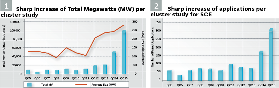
The deregulation of California’s electricity market in 1996, combined with aggressive state-mandated renewable energy standards, has led to a surge in independently owned generating plants seeking connection to the SCE grid. These plants, primarily wind turbines and solar photovoltaic facilities, are often located in remote areas where open space, wind, and sunlight are abundant. These remote locations are connected to the major load centers in the greater Los Angeles basin by a limited number of transmission corridors. As more generation comes online, the power flowing through these corridors can reach or exceed available capacity, causing overloads and other adverse conditions during outages. Mitigation is necessary to prevent equipment damage and maintain grid stability. (see Figures 1 and 2).
Mitigating the Risks: New Transmission Lines vs Remedial Action Scheme

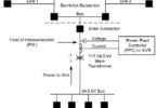
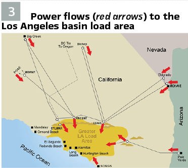
Mitigation options include building new transmission lines or installing a Remedial Action Scheme (RAS). While both methods aim to protect system reliability and safety, building new lines is costly and time-consuming, making RAS adoption a relatively inexpensive and swifter solution. RAS acts as the next line of defense after the protection system clears a fault, maintaining a secure operating state for reliable operation. Almost all bulk power lines bringing generation or imports into the Los Angeles basin load area, as depicted in Figure 3, are monitored and controlled by local remedial action schemes.
Let’s dive deeper into what power system problems can occur, some examples, and how Remedial Action Schemes (RAS) are designed to mitigate them:
- Thermal Overloads, this refers to the ability of power system components, such as transmission lines and transformer banks, to operate within their thermal limits. When the current flowing through these components exceeds their rated capacity, it can cause overheating, leading to potential damage or failure.
Overloading of transmission lines or transformer banks can occur under several conditions. One of them is that a component in the power system is out of service due to faults or equipment failures, the remaining equipment may be forced to carry additional load, potentially leading to overload. RAS can help mitigate thermal issues by detecting the component out status and/or equipment overloading conditions and performing the following remedial actions:- Load Shedding: Automatically disconnecting pre-determined loads to reduce the overall current flow
- Generation Control: Adjusting the output of generators to balance the load and prevent overloading specific components
- Voltage Stability involves maintaining the voltage levels within acceptable limits to ensure reliable operation of the power system. Voltage instability can lead to voltage collapse, resulting in blackouts.
In a heavily loaded metropolitan area, insufficient reactive power support can lead to voltage drops. If the voltage drops significantly and cannot be restored, it can result in a voltage collapse with cascading effects, causing widespread blackouts.
In addition, power systems with long transmission lines, such as those connecting remote renewable energy sources to urban centers, can experience voltage instability due to high impedance and insufficient reactive power compensation.
RAS addresses voltage stability by:- Reactive Power Compensation: Controlling devices like capacitors and reactors to manage reactive power and maintain voltage levels
- Voltage Control Devices: Controlling devices such as Static VAR Compensators (SVC) to dynamically control voltage.
- Transient Stability refers to the power system’s ability to maintain synchronism when subjected to a large disturbance, such as a short circuit or sudden loss of a generator. Transient instability can cause generators to lose synchronism, leading to system separation and blackouts.
A sudden fault in the power system, such as a short circuit, can cause a power system component(s) to trip. This sudden loss of power system components including lines, transformers or generators can lead to transient instability, where the remaining generators struggle to maintain synchronism. Rapid switching operations can also cause stability issues, such as connecting or disconnecting large loads or transmission lines, can cause transient instability. For example, switching on a large industrial load can cause significant disturbances in the power system.
RAS enhances transient stability by:- Post Disturbance: Taking quick actions like tripping generators, shedding loads or reconfiguring the system to minimize further impact on the system
- Controlled Islanding: Deliberately separating the power system into smaller, stable islands to prevent a cascading failure
By addressing these three critical areas, RAS plays a vital role in maintaining the reliability and stability of SCE’s power grid.
Stand-Alone RASs: Solution for the 90s
SCE has implemented 20 RASs across its service territory since its inception. These systems of relays and logical algorithms automatically disconnect generators, load, or both under certain conditions. Each RAS is designed as a stand-alone system, including all necessary equipment.
While stand-alone RASs have been effective, they are becoming less feasible as the number of RASs increases and interactions between RASs in the same areas become more frequent. Implementing more stand-alone RASs in a timely, cost-effective, and operationally sound manner is challenging. As new generation interconnections drive the need for more complex RASs, current technologies are reaching their limits in managing multiple RAS interactions.
Centralized Remedial Action Scheme: The Future of Grid Stability
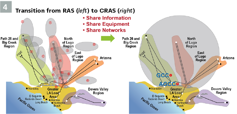
Imagine a high-speed command center, orchestrating the flow of electricity across California with precision and foresight. That’s CRAS-a next-generation approach that centralizes decision-making. SCE believes a Centralized Remedial Action Scheme (CRAS) is a more feasible solution for several reasons: (Figure 4).
- Complexity Management: CRAS can handle the complexity required to interconnect large numbers of geographically clustered generation projects, avoiding excessive tripping of generators and customer load
- Accelerated Implementation: CRAS will expedite RAS implementation and the work necessary to bring new generators online
- Cost Efficiency: The costs of CRAS technology are offset by the avoided costs of multiple sets of relays required for stand-alone RASs
- CRAS differs from traditional stand-alone RASs by centralizing the control logic in one main location at the Grid Control Center (GCC) and a backup location at the Alternate GCC (AGCC) to mitigate grid problems, rather than implementing the control logic within the relays at multiple distributed locations. This allows for more precise management of the interdependency between generation and transmission. CRAS improvements over stand-alone RASs include:
- Centralized Logic Processing: Logic processing at control centers instead of substations allows for easier changes/updates
- Improved Architecture: Better design for protecting transmission assets
- Enhanced System Awareness: Global reach across incorporated RASs and the ability to incorporate external system data, including synchrophasors, preventing cascading failures
- Advanced Automation: Enhanced automation and simulation capabilities allow for comprehensive testing, debugging, and event analysis, reducing testing labor via automated procedures
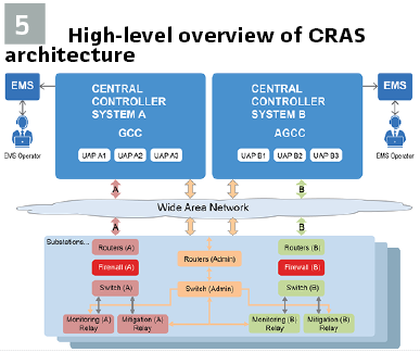
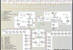
Figure 5 gives a high-level overview of the CRAS system architecture. The system is fully redundant with duplicated A and B subsystems operating in parallel. Each A or B subsystem has its own central controller system (CCS) with three unified analytic platforms (UAP), monitoring relays, mitigation relays, and telecommunication circuits.
Today, SCE has 12 standalone RAS and 4 CRAS applications in the power system.
CRAS Central Controller System and Arming
The central controller system is located at the GCC and AGCC. Each performs independent analytic functions. The central controller system receives information via R-GOOSE from the CRAS monitoring and mitigating relays and runs the associated CRAS analytics based on the information received. Details are as below:
- Processes measurements (e.g., line/bank flows, loads and generation)
- Processes contingencies
- Interfaces with external data sources
- Calculates required arming and determines mitigation actions
- Sends mitigation commands
- Verifies mitigation has taken place
The CRAS central controller system arms and disarms specified contingencies based on predetermined arming equations and mitigation resources.
CRAS Monitoring and Mitigation
In CRAS, multiple CRAS relays are installed at different substations which function as either line/bank monitors, or as load and generation tripping relays. The line/bank monitor relays send line/bank status and load flow information upstream to the central controllers in GCC and AGCC. The controllers determine if the CRAS should be armed for contingency mitigation. Load flow information is sent as low-priority packets, whereas line/bank status information (contingencies) is sent as high-priority packets. If the central controllers decide that a mitigation is necessary, high priority packets will be sent to the appropriate load and generation tripping relays indicating the relays can carry out the appropriate tripping action.
The line/bank monitor logic requires that line/bank breakers be open and that there be no current flowing in the breakers, or alternatively, that protective relays have issued a trip to the associated breakers, in order to declare the monitored line/bank as being open.
The tripping relay logic employs a two-out-of-three voting scheme to ensure that erroneously generated tripping signals from a CRAS central controller do not cause a false trip operation. Each of the three UAPs in a central controller sends out a separate trip signal to a specific tripping relay when a RAS mitigation operation is required. The two-out-of-three voter ensures that at least two UAPs are on-line, and that at least two of the on-line UAPs have sent a trip signal. The UAPs send the trip signals to the relays on the high-priority R-GOOSE stream.
In the cases where the load and generation (typically owned by the interconnecting customers) being tripped are outside of the SCE territory, NERC CIP implications preclude installing relays with R-GOOSE interface at these load and generation locations. The solution is to install target tripping relays at the interconnecting customer’s sites, connect them with the SCE’s tripping relays via dedicated communication circuits with point-to-pint protocols by which the tripping signals will be transferred from SCE’s tripping relays to the interconnecting customer’s tripping relays.
Continuous Improvement and Modernization: A case study for the leap to Layer 3
SCE’s initial CRAS was installed using the non-routable Layer 2 Generic Object-Oriented Substation Event (GOOSE) protocol as the Layer 3 “Routable” GOOSE (R-GOOSE) over an Ethernet WAN was just being investigated by the industry. As technology advances, SCE recognizes the need to adopt the more robust and flexible Layer 3 (L3) R-GOOSE protocol. This modernization effort aims to enhance the efficiency and reliability of the CRAS system, which is a critical component of SCE’s infrastructure.
The main issue with using Layer 2 GOOSE over the Wide Area Network (WAN) is that GOOSE was not designed for the WAN:
- CRAS depends on very high volume of fast-sampled digitized data. Using GOOSE over WAN without workarounds will flood a network with a “GOOSE storm” when grid events occur (relays all talking at the same time, and retransmitting messages)
- Every device on the network hears all GOOSE messages, has to look at header to see if message intended for it
The secondary issue – but one with significant risk and cost implications – is that the workarounds required for GOOSE to function on the WAN are highly customized, non-standard, complicated, and difficult to troubleshoot:
- RISK implications – workarounds are less stable than “normal” Layer 3 networking, more prone to outages, harder to recover, and not scalable
- COST implications – one-off custom solutions are inherently more expensive to maintain, usually by orders of magnitude
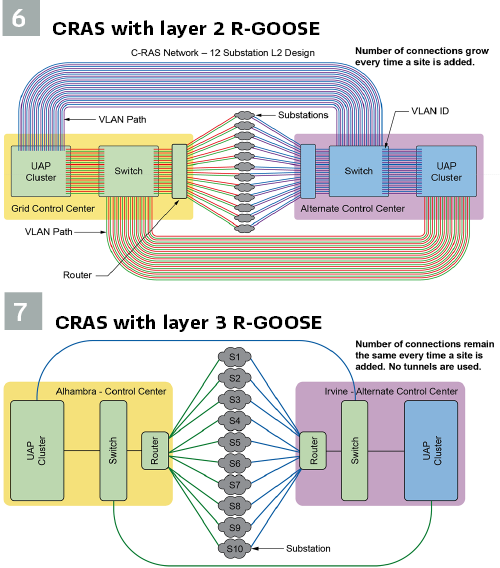
One of the workarounds is to create multiple separate virtual network paths called VLANs, which requires customized settings on each device involved. These network paths proliferate and add complexity and risk with each additional RAS installed. (see Figure 6).
By contrast, R-GOOSE has a simpler, more scalable design suited for WAN application. Communications are targeted (addressed to each device) as shown in Figure 7.
This transition involves several key steps and considerations to ensure a smooth and effective upgrade:
- Telecom Network Changes: Modifications to add R-GOOSE connectivity to the existing substations
- Equipment Replacement: Replacement of outdated relays with R-GOOSE compliant relays
- System Monitoring: Additions to system monitoring capability for the new L3 CRAS and removal of monitoring for the old L2 CRAS
- Testing and Commissioning: Thorough verification of the new L3 CRAS system performance
L3 R-GOOSE Successful Outcome and Looking Ahead: With the system upgrade completed in 2023, all SCE CRASs are now on L3 R-GOOSE protocol, a significant step forward for SCE in enhancing the reliability and efficiency of its Remedial Action Schemes. By leveraging existing capabilities and minimizing downtime, SCE is poised to ensure a seamless transition that will benefit its infrastructure and operations for years to come.
Who’s behind the scenes for SCE? Meet Bill Zhang, SCE’s resident expert
With over three decades of experience, Bill Zhang is a distinguished expert in the field of Protection Engineering, specializing in Remedial Action Schemes (RAS) and Centralized Remedial Action Schemes (CRAS). Year after year, Bill continues to be a top performer for the Protection Engineering team, consistently demonstrating his exceptional skills and dedication.
Recognized as the subject matter expert for CRAS/RAS at Southern California Edison, Bill possesses extensive knowledge about the outward facing WECC RASRS Committee and Reliability Coordinator RC West, which is responsible, which is responsible for approving SCE’s CRAS/RASs. His organizational skills, deep technical expertise, and availability for questions and support have been invaluable to his colleagues and clients. He had the following insights to offer about the future of CRAS.
How do you ensure that the CRAS system maintains the grid reliability and stability under varying grid conditions and unexpected contingencies?
Stakeholder Collaboration: Work closely with all stakeholders, including Transmission Planning, Substation Engineering GCC, and Telecom teams, and Telecom teams, to ensure all aspects of the system are aligned and functioning correctly
Robust Design and Engineering: Design the system with better scalability to handle increased loads and additional RASs without compromising performance; Incorporate redundant systems and pathways to ensure continuous operation even if one component fails
Regular Testing and Simulation: Conduct regular simulations of various contingency scenarios to test the system’s response and identify weaknesses
In what ways do you see automation and artificial intelligence (AI) playing a role in the future development and operation of CRAS?
- Mitigation Algorithm Improvement: AI to help identify anomalies and patterns that might indicate emerging problems by analyzing historical data and real-time inputs
- Engineering Design: Automation and AI could be utilized in the future to create engineering drawings (schematics, wiring, and even CRAS logic) and relay settings
- Simulation and Testing: AI-driven simulations could test designs under various conditions, reducing the need for physical prototypes and accelerating the development process
How do you ensure that the CRAS system complies with regulatory standards and guidelines?
- Understanding PRC-012-2 Requirements: PRC-012-2 aims to ensure that Remedial Action Schemes do not introduce unintentional or unacceptable reliability risks to the Bulk Electric System (BES)
- Robust Compliance Framework: Implement a comprehensive internal control framework to monitor and ensure compliance with PRC-012-2 requirements; Conduct regular internal and external audits to verify compliance and identify areas for improvement
- Documentation, Reporting and Evidence Collection: Maintain comprehensive documentation of all compliance activities, including data collection, analysis, and reporting; Collect and organize evidence to support compliance during audits and regulatory reviews
What innovative approaches or technologies have been explored to enhance the performance and capabilities of the CRAS system?
- Upgrade to L3 R-GOOSE: This upgrade eliminated the L2 GOOSE drawbacks as mentioned earlier and brought the CRAS system to the current standard to enhance the reliability and efficiency of the Remedial Action Schemes
- Multiprotocol Label Switching (MPLS): This technology allowed for better utilization of network resources and bandwidth for CRAS, and enhanced network scalability, performance, and cost-effectiveness compared to TDM networks
Environmental Impact: How does the implementation of CRAS contribute to SCE’s environmental goals?
CRAS supports SCE’s efforts to integrate more renewable energy sources, such as wind and solar power, etc. thereby minimizing the need for fossil fuel generation and reducing greenhouse gas emissions.
By optimizing the use of existing transmission infrastructure and reducing the need for new construction, CRAS minimizes the need for new transmission rights-of-way.
How does the CRAS system impact SCE’s customers, and what measures are taken to ensure minimal disruption and maximum benefit to end-users?
By ensuring the grid remains stable, CRAS minimizes the likelihood of service interruptions, providing more reliable electricity to customers.
Measures taken: CRAS uses advanced sensors and monitoring tools to continuously assess the grid’s status and quickly adjust the grid’s operation to maintain stability. This allows for quick responses to potential issues, minimizing disruption.
Continuously pursue upgrades to the CRAS technology and infrastructure to enhance the system performance and reliability.
Biographies:

Bill Zhang, Senior Engineer in Protection Engineering at Southern California Edison (SCE) Company, has over 30 years of industry experience in power system protection, planning and telecommunications. He is currently the subject matter expert for Remedial Action Schemes (RAS) at SCE and a member of the Western Electricity Coordination Council RASRS Subcommittee. Before joining SCE, he was a Senior Protection Engineer with Pepco and AEP respectively working on fault analysis, protection scheme design, relay settings and SPS/RAS. Prior to that he also worked as a Transmission Planning Engineer with a utility company and a Telecom Engineer with a telecom manufacturer. Bill received his BSEE degree from the North China Electric Power University and MSEE from the University of Manitoba, Canada.

Simeon “Jet” Rodriguez is a seasoned electrical engineer with nearly two decades at Southern California Edison (SCE). He holds a B.S. in Electrical Engineering and a Certificate in Power Systems from California State Polytechnic University, Pomona. Jet began his career at SCE as a Distribution Standards Engineer, later becoming a Substation Projects Engineer, Compliance Engineer, and various Engineering Manager roles. He has led digital transformation efforts, enhanced substation metrics, and championed a new engineering promotion tool. Currently, Jet is the Engineering Manager for Protection Engineering – RAS/CRAS & Automation, leading SCE’s automation programs and process mapping efforts.