Lessons Learned Six years into Oncor’s DA Deployment
by Jeremy Preas, Oncor Electric Delivery, USA
DA Program Background & Overview:
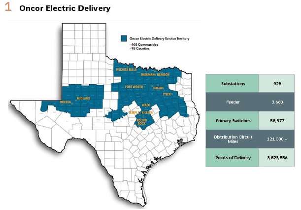
In 2017, Oncor started a 10-year program to modernize its distribution grid. It is focused on deploying 5 Distribution Automation (DA) technologies throughout the service territory on the primary overhead (OH) radial system, which comprises almost 60% of the company’s total distribution circuit miles.
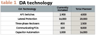
All of the technologies shown in Table 1, except the lateral protection, include some form of communications needs; i.e., SCADA and/or peer-to-peer (P2P) communications. The focus of this paper will highlight lessons learned during the deployment of the Automatic Feeder Switching (AFS) fleet, which is still ongoing at Oncor. The first half of the article will discuss the AFS Deployment program from a project management perspective and the latter half will focus on technical topics.
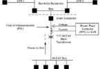
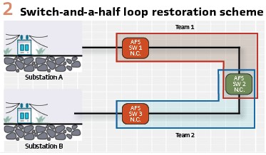
AFS Overview: The automated feeder switching system Oncor deployed utilizes switch-and-a-half loop restoration in which P2P communications were set up between each switch and the relevant substations to coordinate the fault location, isolation, and service restoration (FLISR) function autonomously. Oncor developed a Distribution RTU program, called the Substation Interface Management System (SIMS), placed in the relevant substation, to collect feeder loading which is supplied to the field devices as well as monitor the feeder breakers for manual or UF/UVLS operations in order to disable automatic restoration of the field devices.
In support of DA Deployment, Oncor also upgrades substation relaying to support the data requirements of the SIMS units and coordinate better with the reclosing scheme on the feeder circuit. In addition, the relay upgrades support the effort to upgrade substations with more control over low-set instantaneous, reclosing, event record retrieval and data security (Figure 2).
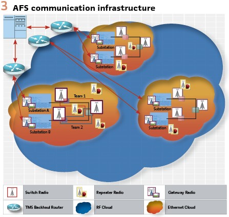
AFS Communications Overview: Oncor uses a two-layer communication system to enable the AFS system. The first layer is an existing SCADA system that connects the TMS/DMS to the substation. During the deployment of the AFS system, Oncor concurrently upgraded this layer from primarily legacy POTS to a mix of licensed and unlicensed RF, microwave, cell modem, and fiber under the Telecomm Refresh Program (TRP). The second layer, which connects the substation to the field device and each field device comprising a “Team of Switches,” was non-existent before the DA Deployment program and had to be established with the roll out of new devices installed onto the distribution grid. This second layer is ~90% RF Mesh utilizing the unlicensed “900 MHz band”, and ~10% fiber. The majority of the AFS is an Ethernet-IP Network. Although, a small portion of the first devices installed in 2016 and 2017 were serial connected. (see Figure 3).
Project Management
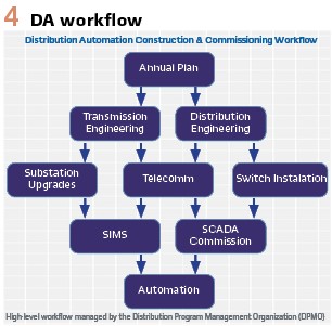
For the AFS roll out, Oncor developed a robust workflow. Along the way, the team learned many valuable lessons that both supported the designed workflows as well as suggested better practices to implement. The following narrative discusses a few of the key points. (see Figure 4).
Chasing SAIDI: Initially, Oncor planned to install AFS to a prioritized list of locations based on customer reliability indices in order to improve the worst performing feeders. However, once the penetration of these devices reached a certain level, it was recognized that this did not support a holistic approach to the design of the communications infrastructure, optimize the movement of construction crews across the system, nor optimize the efficiency of material handling from a District storeroom perspective. The “chasing SAIDI” approach was jettisoned in favor of a more efficient geographical approach. The team still prioritizes candidate circuits by reliability performance. However, we married this philosophy with the geographical approach by automating additional circuits in the local area as well. This allowed the Telecomm Engineering group to design P2P infrastructure, including repeater radios more efficiently. Before this change, the team found that some areas ended up overbuilt with too many repeaters. While other areas were technically underbuilt, and required the new projects to include movement of some existing repeaters; thus increasing CapEx spending unnecessarily. In addition, this geographical approach allows the Transmission groups to upgrade all of the feeder breakers at the substation, or at least the Transformer bank, at the same time.
Master Buildout Plan: Since Texas, and subsequently Oncor, is realizing unprecedented growth with the influx of new businesses and migration of the populace, it was difficult to create a detailed “Master Buildout Plan” of the AFS system. However, to support the geographical approach to the Annual Plan, it was still vital to create such a Master Buildout Plan. The team created a loose set of rules that could anticipate inclusion of automation on a given circuit. These rules include, but are not limited to:
- Customer/Business count
- Possible availability of a Tie circuit
- Amount of reconductoring required to support automation
The Master Buildout Plan is not a precise forecast, but as the Annual Plan targets a specific geographic area, the Planning and Telecomm Engineering groups have a plausible view of the area to design an efficient and robust support system to optimize costs, construction activities, and equipment delivery and storage.
Third-party Warehousing & Device Programming: In order to ensure that Oncor’s storerooms were not overburdened with dormant equipment stored outdoors, which impacts unassembled equipment exposed to the elements and increases inventory carrying costs, Oncor contracted the AFS manufacturer to program the switches and radios, as well as store the equipment in a vendor operated warehouse in Dallas, Texas until the equipment was ready to be installed by construction crews. Bringing them in to install the settings into the controls and radios, offered an additional sanity check to the design. Since Oncor started using the vendor’s services, the switches arrive in good operating condition, and programmed correctly with 99.5% success rate.
Technical
As the AFS system and RF Mesh expanded, specifically in the Dallas/Ft. Worth Metroplex (DFW Metro) area, the performance degraded. In late 2019, at any given moment, up to 60% of the AFS switching devices may not have been in a “Ready” state, and Distribution Operations Center (DOC) Operators complained that communications would go down when sending control commands, and many devices would momentarily lose communications hundreds of times per week. Upon further investigation the team found several areas to focus on for improvements. Namely these were:
- Radio, Repeater, Gateway configurations
- Antenna craftsmanship
- RF Mesh configuration
- SCADA Master CFE realignment
- Maintenance and Repair
Oncor embarked on a DA Triage effort in which the goal is 98% communications availability and 97% switch teams in “ready” state.
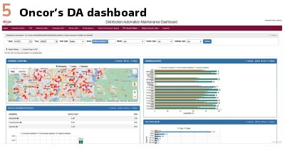
Fleet Management: In order to support a rigorous DA triage and accurate KPIs, Oncor created a “DA Dashboard” and purchased a radio fleet management application from the manufacturer. The application allows Oncor to monitor channel utilization as well as a host of other KPIs, update firmware, change radio and mesh configurations, and several other functions that aid in the management of a large fleet of radios. The DA Dashboard is a homegrown data visualization tool that allows managers, technicians, engineers, etc. to monitor switches and their teams, trouble tickets and the RF Mesh, live or historically, in a system-wide view or down to the substation/feeder level. (see Figure 5).
KPIs: Before discussing the DA triage efforts, a few key metrics that highlight the health of the AFS system and the supporting RF Mesh should be defined. While these are not all of the available metrics, they are a good high-level summary of the health of the system:
- Communications Availability – measures whether messages are routing through the P2P mesh and the SCADA backhaul:
- Percent Communications Availability –Over a timeframe specified by the user (usually 24 hours, or 1 week),
- Communications Availability Snapshot – number of switches with active communications divided by the total number of switches at the time of data extraction.
- Count of Loss of Communications – Over a given period of time this metric is a count of the number of times Communications go down for a specific device. Intermittent Comms was a significant cause of low performance of the AFS system.
- Automation Availability – measures if a Team of switches will automatically perform the FLISR function. The algorithm behind this monitor takes into account if the Team or a Team Member is in “ready” state (a SCADA point), is in remote (as opposed to local), and the comms are good. In addition to this, the algorithm also takes into account the existence of an active switching order, or if the Team has been taken “Out of Ready” via manual intervention. This metric comes in two flavors:
Percent Automation Availability –over a time period set by the user,
Sum of aggregate minutes of “Switch/Team Ready” of all switches in population
- Automation Availability Snapshot – number of switch teams available for automatic operations divided by the total number of teams at the time of data extraction
- Channel Utilization – Number of messages through a given radio (either in the field device, a repeater, or a gateway) divided by the maximum allowed messages
Antennas: One of the first places to focus was the coax connections on the antennas as well as at the radio. Technicians were quick to point to the terminations as causes of intermittent comms and poor signal strength. It is very easy to overtighten these connections, unless properly trained and with the correct tools, construction crews can and will overtighten them. Also, due to the construction of a coax cable, it is not always evident through visual inspection that the termination is faulty. The team reached out to the Distribution Operations Technician (DOT) workforce to help maintain and troubleshoot the RF Mesh, including the antenna components. They created troubleshooting training assisted by the Telecomm Technician group.
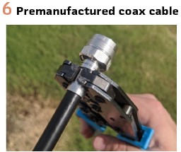
They also provided the DOTs with cable analyzers to test antennas and the coaxial cable run from the radio to the antenna. Oncor also switched to premanufactured coax cables cut to length with both ends factory terminated. While the premanufactured cables alleviated much of the craftsmanship issues, it should be noted that there are still a significant number of locations that cannot be built to exact standards, as well as failed coax cables, that require the workforce to maintain best practices when it comes to coax termination craftsmanship. (Figure 6).
DOC Review: During the initial review, the Oncor team found that many switches and teams were left in an abnormal state after construction, troubleshooting, or repair activities. Abnormal states, such as: “Local,” “Prohibit Restoration” or, “Hot Line Tag” for example. Operators at the DOCs took on the responsibility of reviewing every AFS device for abnormal states once a week, and returned to normal those that were left in the wrong state inadvertently.
After the DOCs began reviewing the status of the Switches and the DOTs visited every switch and repeater location to inspect coax terminations, 1 week Automation Availability rose from mid-40% to low-60%. Oncor now reviews all AFS devices for abnormal state once every 24 hrs.
Automatic Alerts: A healthy maintenance program is vital to a large deployment of DA on any grid. It can become cumbersome to monitor and respond to failures and degradation if there are not some automatic alerts or controls on the expediency of repairs. Early on in the investigations, it was found that many problems were going unreported. Typically, Oncor Technicians (P&C, Telecomm, DOTs) respond quickly and effectively to trouble they are aware of, but they just were not aware of a substantial amount of the problems. Oncor has set up back-office analytics to monitor and alarm on certain incoming SCADA points.
The system automatically creates a trouble ticket and an OMS tag for the following:
- Battery failures
- Temperature Sensor Alarm
- Communications Down
These automatic notifications significantly reduced the time between problem inception and Technician notification. For example, the Battery failure and Temperature Sensor notifications reduced the time to notification down from 44 hours on average to less than one hour (the typical polling rate). The Communications Down notifications went from only 30% being reported within 153.6 hours on average to 97.4% being reported within 5 hours.
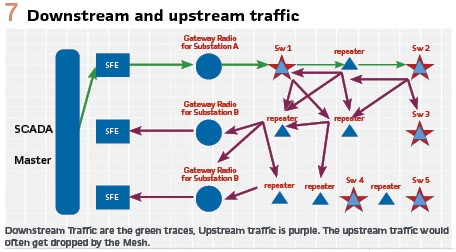
Control Issue & Intermittent Comms: Personnel monitoring the traffic from the SCADA Master, the TMS backhaul, the substation gateway, and at a specific field device…with TraceRoute and Wireshark, found that signals from the SCADA Master made it to the field device nearly 100% of the time. However, during the testing, the response from the field device to the SCADA Master (which is a key part of a SBO SCADA control) would make it to the SCADA Master at a <50% success rate. Intermittent Comms (i.e., Comms going up and down) was excessive during testing as well as in practice. This was because the mesh had too many routes available and too many points of egress out of the mesh for the messages. In addition, many of the links were weak. In other words, a message would get dropped on its way to the Master by a link that was too weak; this link reported stronger when the message was first broadcast. The investigation team took note, that traffic from the head-end to the gateway radio was highly reliable. (see Figure 7).
CFE Realignment & Radio configurations: The traffic from the Scada Master to the field device had always been routed towards one gateway radio. This radio was located at the substation (or the substation of the Alternate Source) of the target device. Therefore, the message only had to travel a few hops. However, field devices were not limited to one gateway radio. The message was broadcast and depending on prevalent conditions (weather, coax cable craftsmanship, battery health, tree growth, etc.) the message had few limitations to the route it could take.
Oncor first opted to limit the points of egress by limiting the number of gateway radios a switch radio or repeater could communicate with. Since the SCADA Master CFE and Gateway radios were already locked to each other via one path, the team reorganized the CFE Line assignments to ensure that Gateway Radios that were at substations in which feeder circuits served as alternate sources for each other did not share the same CFE Lines. Although highly unlikely, the loss of a CFE Line would not mean the loss of communications to an entire geographic area.
Second, in order to manage the findings around signal strength, message routing, etc. Oncor worked with the AFS manufacturer (which also manufactures the mesh radios) to optimize the radio configurations. The team tightened the radio parameters that helped determine optimal paths. For example, the minimum link threshold (dBm) was raised to reduce the number of radios a transmitter could choose. Several consistently marginal links were blacklisted which did not allow the transmitting radio to ever use the link even if it was strong at the time of broad/unicast.
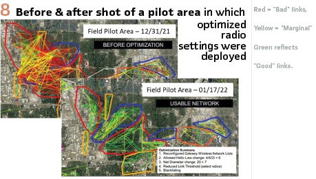
The number of message retries were increased to increase the chance a message was successfully acknowledged. Also, the number of “hops” a message was allowed to take was decreased to force the routing through stronger links; however, it was set just high enough to allow redundancy in the network. (see Figure 8).
The Piney Woods of East Texas: One area has been especially difficult to remediate. The piney woods of East Texas have proven to be cumbersome for the unlicensed 900 MHz band. The size of pine needles are large and dense enough to interfere with the small wavelengths of the band. The trees are tall enough that increasing antenna height is impractical and too many repeaters would be required to “bounce” around the trees. While this area is home to less than 3% of the AFS fleet, it represents almost 15% of our trouble tickets, Percent-Comms availability is around 80%, and Percent-Automation Availability is around 60%. Oncor is currently testing radios and network architecture utilizing a spectrum of licensed 200 MHz. The pine needles should be almost invisible to the band. We are also considering a Point to Multi-point architecture where the hub can be raised to a suitable height while the endpoints can remain at the more acceptable 60’ height. Currently, we have 22 switches and 7 substations under the “220 Pilot.” Thus far, the pilot has reflected 99%+ Communications Availability and Automation Availability.
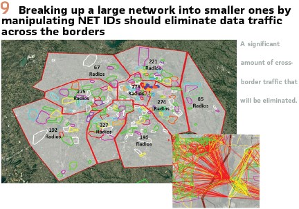
Expansion Proofing: As the penetration of the AFS Fleet continues to increase through the DA Deployment program and system expansion, Oncor is concerned that channel utilization will increase to a level that may fill up available bandwidth. During the DA Triage investigation, in some areas in the DFW Metroplex, the team recorded 30-minute moving average slot utilizations near 70%; at 100% utilizations, messages will start to get dropped. Currently, the entire RF Mesh shares a single Network ID. Even though the team has optimized and tuned the RF mesh, which essentially restricts unicast messages, the broadcast messages could technically be heard by every radio on a shared Net ID; thus increasing realized channel utilization. However, different Net IDs do not simultaneously share the same frequency because the radios in different Net IDs have different frequency hopping rotations. After piloting Net ID segmentation in two areas, the channel utilizations dropped from ~65% down to ~7%. Oncor sees this as a successful pilot. By the end of Q3 2023, Oncor will break up the DFW Metroplex geographically into multiple Net IDs. (Figure 9).
The AFS Fleet Today
As of July 2023, the Percent Automation Availability is consistently around 76% – 80%. Generally, approximately 15% of the AFS fleet is out of ready due to unrelated construction and projects (e.g. system expansion/modernization, reconductoring jobs, trouble repair to assets due to wildlife, down poles, storm damage, etc.), and an additional 10% (and decreasing) is out due to failures and repairs needed within the fleet itself. Percent Comms Availability consistently rides around 97%. Around 100 locations have a 1-week loss of comms count above 15.
Through continued vigilance on the repairs needed via the ticketing systems, staying current with battery replacements and other PM, and continually training and developing construction crews, Technicians, DOC personnel, and engineering, Oncor will get Comms Availability to 98%, Automation Availability to ~85%-90% (taking into account unrelated construction activities), and intermittent comms below 5 per week for any device.
Biography:

Jeremy Preas has a 17-year background with Oncor Electric Delivery after receiving his B.S. in Electrical Engineering Technology from Texas Tech University in 2006. He also received an MBA from Texas A&M – Commerce in 2012. Jeremy has held various positions within Oncor such as Transmission Protection & Control Technician, Relaying Support Specialist in Transmission’s System Protection Group, Technical Support Manager for the East Distribution Operations Center, as well as the DOC Manager. He currently manages the Scada Automation group which is responsible for engineering, design, operations support, and technical analysis for Oncor’s Distribution SCADA system and automated devices.