by Alexander Tsylin, Orsted, Denmark and Karthick Muthiah, Orsted, Malaysia
The offshore wind sector is rapidly expanding as countries turn to this cost-effective renewable energy to reduce emissions and meet net-zero targets. Supporting this growth requires innovative approaches to streamline design, accelerate project delivery, and safely reach milestones like first power. The evolution of protection, automation, and control systems has enabled Digital Substation (DSS) technology, which holds great potential to support these objectives. The shift from conventional towards DSS design digitizes analog and hardwired interfaces between primary systems (HV equipment) and secondary systems (Protection & Control (P&C), Substation Control System (SCS), Wind Turbine Generator (WTG) SCADA, metering, LV, and auxiliaries) using IEC 61850 collection of standards.
Key Aspects of OWF Projects
OWFs have unique aspects that influence their design, execution, and ongoing operation, presenting complex challenges throughout development and maintenance.
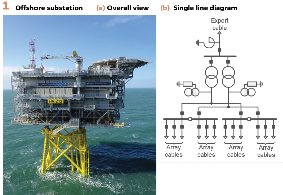
OWF Design: OWFs differ in size, capacity, and design, but the typical architecture of an OWF is illustrated in Figure 2.
Power from multiple Wind Turbine Generators (WTGs) is collected via array cables and transmitted to the Offshore Substation (OSS), which is typically designed as a large steel structure with multiple decks – refer to Figure 1. The OSS houses HV equipment like Gas-Insulated Switchgear (GIS), transformers, shunt reactors, along with P&C, SCS, WTG SCADA, metering and other LV, utility, and auxiliary systems. P&C panels are usually located within GIS rooms near the primary equipment.
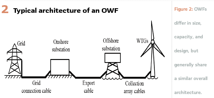
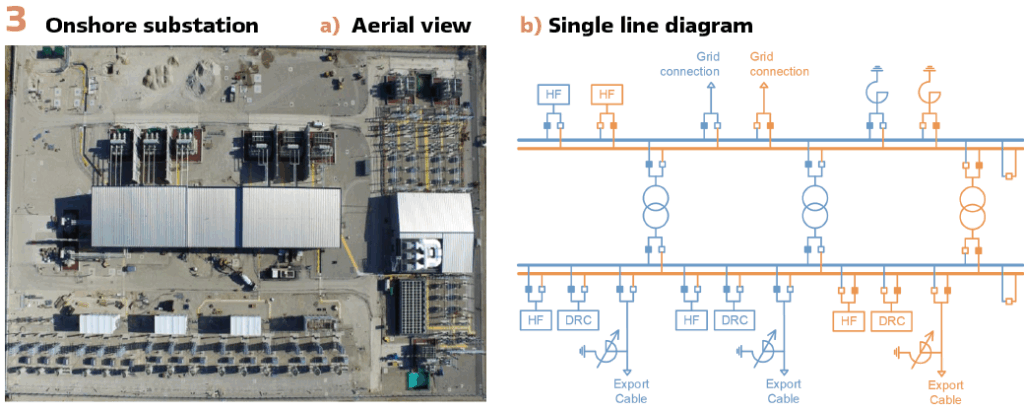
Power from the OSS is transmitted via submarine export cables to the Onshore Substation (OnSS), usually located near the grid owner’s substation – refer to Figure 3. From the OnSS, power is transferred to the grid through grid connection cables.
The OnSS layout is optimized to minimize footprint, often using GIS in separate halls. Most HV equipment, such as transformers, shunt reactors, Harmonic Filters (HF), and switchgear for Dynamic Reactive Compensation (DRC) equipment, is installed outdoors. Secondary systems like SCS, LV, and auxiliaries are housed in a control building. P&C panels may be in GIS halls or the control building. Some OnSS use Air-Insulated Switchgear (AIS), which requires more space.
OWF Project Execution: An OWF is a large-scale project spanning multiple sites – from onshore grid connection and OnSS to offshore cable routes, OSS, and WTGs – requiring careful planning and coordination. The OnSS and OSS are essential elements, with their design, fabrication, installation, and commissioning on the project’s critical path. OSS HV equipment and secondary systems are usually installed and pre-commissioned at the shipyard under tight schedules to meet fixed sail-away dates, while OnSS timelines are driven by grid connection deadlines, often before first power.
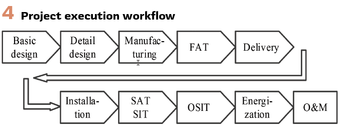
A generic project execution workflow for the P&C scope and its interfaces is illustrated in Figure 4.
A common strategy for successful OnSS and OSS execution is frontloading P&C system testing during Factory Acceptance Testing (FAT), minimizing Site Acceptance Testing (SAT), Site Integration Testing (SIT) as well as end-to-end Offshore Site Integration Testing (OSIT) to essential tasks only. Adopting standardized designs for OnSS and OSS streamlines execution, boosting efficiency and saving time from design through FAT, SAT, SIT, and OSIT phases.
OWF Operation and Maintenance: Operation and Maintenance (O&M) of OWFs present unique challenges, as OnSS and OSS are typically unmanned and OSS access is often limited by weather, making remote monitoring and troubleshooting essential. Ensuring high reliability and availability of the P&C system is crucial for maximizing power generation and enhancing the project’s overall business case. Since retrofitting P&C systems requires outages, optimizing schedules is vital to minimize downtime and revenue loss.
Digital Substation Concepts for OWF
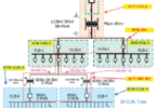
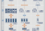
Three common P&C system designs using IEC 61850 and DSS have emerged: conventional substations with a station bus (the OWF industry standard), hybrid DSS, and full DSS, reflecting the evolution from traditional to fully digital solutions (see Figure 5). In a conventional substation with a station bus (Figure 5a), analog signals from Current Transformers (CTs) and Voltage Transformers (VTs), and binary signals from HV equipment, are connected directly to P&C Intelligent Electronic Devices (IEDs) via hardwiring. Most inter-IED signals are also hardwired, while communication with the SCS or remote gateway uses an IEC 61850 station bus. This communication is mainly client/server for monitoring and control, with limited Generic Object-Oriented Substation Event (GOOSE) messages used for some functions like interlocking and disturbance recorder activation. Analog interfaces to other secondary systems, such as metering and WTG SCADA, remain hardwired, with possible station bus communication to the SCS.
In a hybrid DSS setup (Figure 5b), analog signals from CTs, VTs, and binary signals from HV equipment, are connected to Merging Units (MUs) via hardwiring. These signals are then sent as Sampled Values (SV) and GOOSE messages over the process bus to P&C IEDs.
All communication between P&C IEDs and with the SCS or remote gateway uses the station bus, combining client/server monitoring with GOOSE-based horizontal communication for all P&C functions. Interfaces to other secondary systems, like metering and WTG SCADA, are digitalized and integrated into both process and station buses where applicable.
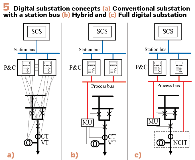
In a full DSS setup (Figure 5c), conventional CTs and VTs are replaced with Non-Conventional Instrument Transformers (NCITs), and the measurement signals are transferred to P&C IEDs as SV via the process bus, either directly or through MUs. Binary signals from HV equipment, are connected to MUs, which then transfer these signals via the process bus to respective P&C IEDs as GOOSE messages. All communication between the P&C IEDs, as well as between these IEDs and the SCS or remote gateway, and interfaces to other secondary systems, such as metering and WTG SCADA, are established in a manner similar to the hybrid DSS setup.
It is important to note that DSS architecture and process/station bus design vary by project, allowing different levels of optimization and integration based on specific requirements.
Value Drivers for Digital Substation
The primary driver for DSS implementation is a compelling business case, which may focus on CAPEX and project execution schedules for some developers, while others emphasize the operational phase and OPEX, depending on their business model. Notably, the key value drivers for OWF developers and operators can differ from those of other stakeholders, such as utilities or TSOs. For instance, utilities may prioritize DSS’s ability to enable rapid and efficient substation expansion or upgrades – an aspect that may be less relevant to OWF developers and operators.
DSS technology offers the following value creation and optimization factors that can greatly benefit OWF projects. However, the business case should go beyond the P&C scope, considering the wider project impact. Since each OWF is unique, the business case is highly project-specific.
Integrated Project Optimization: Integrated project optimization – combining design optimization and standardization – is key to the DSS business case. Rather than a separate factor, it enhances cost savings and schedule efficiency by streamlining design and execution across scopes like P&C, SCS, HV equipment, substation layout, and others. DSS enables standardization that reduces customization, simplifies engineering, and aligns OWF projects. The three DSS concepts offer varying optimization levels, with full DSS providing the most comprehensive integration and standardization across OWFs.
Project Execution and Schedule: optimization are key value drivers for OWFs. DSS technology influences all phases – engineering, manufacturing, FAT, installation, SAT, SIT, and OSIT. Its modular architecture and digital tools enhance flexibility, speeding design and enabling quick adaptation. Manufacturing is streamlined by reducing panel numbers through greater functional integration of IEDs and systems. DSS enables frontloading much of the P&C and interface testing to FAT, extending its duration but shortening SAT, SIT, and OSIT, which accelerates and de-risks overall commissioning, enabling earlier energization and first power. While DSS shortens installation and cabling activities, their impact on the overall substation commissioning schedule is relatively minor.
Capital Expenditures (CAPEX): CAPEX cover hardware, engineering, installation, and commissioning costs across DSS-affected scopes like P&C, SCS, HV equipment like GIS with NCITs, and OSS/OnSS construction. Proper DSS implementation can reduce CAPEX, but savings in P&C and related scopes usually have a moderate impact due to their smaller share of total substation costs. Installation and cabling savings are typically minimal. However, optimizing OSS and OnSS design by reducing standalone protection panels, simplifying interfaces, and shrinking the GIS footprint with NCITs can significantly lower overall costs.
Operating Expenditures (OPEX): OPEX cover O&M activities like preventive and corrective maintenance, remote troubleshooting, and costs tied to system reliability and availability indicators. DSS can streamline processes and reduce manual work, but its impact may be moderate given already optimized OWF O&M practices. DSS also helps reduce retrofit costs for secondary systems by simplifying engineering and schedules, minimizing downtime and resource use, and improving lifecycle cost efficiency.
QHSE: The application of DSS brings several Quality, Health, Safety and Environment (QHSE) benefits, such as heightened safety during commissioning and O&M through the use of NCITs and Fiber Optic (FO) cables. Environmental advantages include reduced greenhouse gas emissions and resource savings from substituting FO cables for copper, minimizing steel in OSS structures, and optimizing civil works for OnSS. While these benefits may significantly enhance the QHSE metrics of OWF projects, they remain challenging to quantify directly.
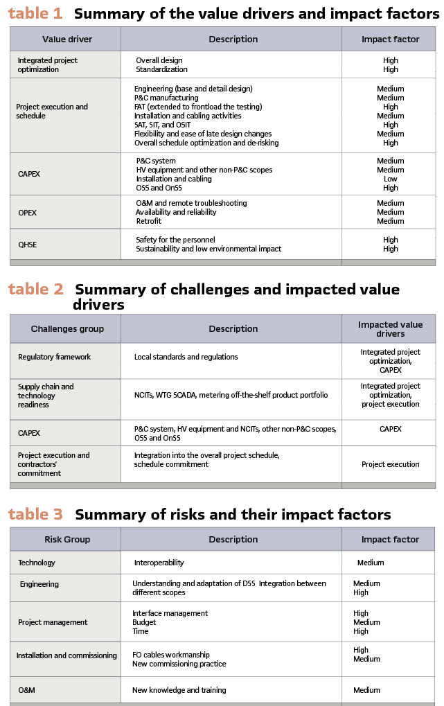
Table 1 summarizes the value drivers that can be realized through the application of DSS technology, evaluating their impact based on the specific characteristics of OWF projects.
Challenges
Challenges in applying DSS technology are practical barriers that can hinder adoption, weaken the business case, or limit its benefits. Addressing the main challenges outlined below is essential for a successful DSS rollout in OWFs.
Regulatory Framework: Local standards and regulations can either prohibit the broad adoption of DSS or impose limitations on specific aspects, such as the use of NCITs, revenue meters and/or power quality meters with digital interface, or the digitalization of critical signals like protection trips. Design constraints such as restrictions on the number of P&C IEDs with specific functions or their panel allocation, can also reduce DSS optimization by limiting integration and flexibility. Overcoming these regulatory and design barriers is key to maximizing DSS benefits.
Supply Chain and Technology Readiness: DSS technology is generally mature, especially for core P&C and SCS components like IEDs, MUs, and network switches.
However, other critical elements for full DSS implementation, such as metering, WTG SCADA, and NCITs, are less developed. This is evident as many Original Equipment Manufacturers (OEMs) do not yet offer a comprehensive range of off-the-shelf products that fully meet the diverse requirements of various design architectures and full DSS project needs.
Capital Expenditures (CAPEX): While DSS technology aims to reduce CAPEX through design optimization, real-world business cases for OWF projects often reveal increased initial costs. P&C expenses can rise due to added components like MUs, network switches, and more complex FAT setups. HV equipment costs may increase with pricier NCITs and added digital interface integration, raising engineering and testing expenses. OSS and OnSS construction costs may stay the same if DSS is not fully integrated into the design, as substation layouts may be influenced by other design constraints. Cabling savings may also be minimal since replacing copper cables with fewer FO cables might still involve higher material costs and require specialized, higher-cost labor.
Project Execution and Contractors’ Commitment: To maximize DSS benefits, full integration into the project schedule – encompassing not just the P&C and its interfaces but also other scopes – is essential, especially for optimizing OSS and OnSS installation and commissioning timelines. However, this is challenging due to multiple parallel activities affecting the critical path. Despite DSS’s potential to streamline schedules, OEMs, system integrators, and Engineering, Procurement, and Construction (EPC) contractors often hesitate to commit to faster timelines due to risks linked to its implementation.
Table 2 summarizes the challenges associated with applying DSS technology and the corresponding affected value drivers.
Risks
Risks associated with DSS implementation are potential issues that could surface during project execution and operation. Proactive mitigation is essential to avoid delays, extra costs, and reduced value. Addressing the key risks outlined below is crucial for successful OWF projects with DSS technology.
Technology: The main technological risk is related to the interoperability issues which can arise when integrating secondary systems’ equipment from different vendors, as their components may not have seamless compatibility with one another. To mitigate this risk, it is crucial to ensure early interoperability assessments, set clear technical standards, conduct pilot tests, and implement detailed interface management to minimize integration challenges.
Engineering: A key risk associated with engineering is the lack of full understanding and adaptation of DSS design, especially during its first-time application. This can lead to integration challenges across scopes, including P&C, HV equipment, metering, and WTG SCADA. This risk can be mitigated through thorough documentation, pilot testing and extensive FAT testing, and close coordination between teams to ensure smooth integration and minimize errors.
Project Management: A key risk in project management is poor coordination among different contractors and suppliers, leading to delays, higher costs, and interface issues that affect the DSS implementation schedule and business case. Unplanned design changes and variation orders can further affect budgets and timelines. Mitigation requires clear project management practices, efficient interface coordination, aligned timelines, flexible contracts, and regular progress reviews to keep the project on track and within budget.
Installation and Commissioning: A key risk during installation and commissioning is poor workmanship with FO cables, which can cause connectivity issues and delays. Additionally, unfamiliarity with new DSS commissioning practices may lead to errors or inefficiencies during SAT, SIT, and OSIT. To mitigate these risks, technicians should receive thorough training on FO cable installation and DSS commissioning procedures. Implementing standardized commissioning protocols and involving experienced personnel to oversee the process will help ensure high-quality results.
Operation and Maintenance: Effective O&M of DSS projects requires new knowledge and training, which may not be readily available, posing a risk of operational inefficiencies and increased downtime. The risk can be mitigated by developing a comprehensive training program for O&M teams to build DSS-specific skills and establish ongoing support from OEMs to ensure smooth system operation and prompt troubleshooting.
Table 3 summarizes the risks associated with project execution and operation when applying DSS technology and their corresponding impact factors.
Enabling Successful Implementation of DSS
To unlock the full potential and optimized business cases of projects with DSS technology, all industry stakeholders must collaborate to address the inherent challenges and risks.
Regulatory bodies play a vital role by updating local requirements and standards to accommodate DSS technology, including provisions for the use of NCITs and advanced metering systems.
Developers, for a successful DSS rollout, must generate market demand, which requires taking on risks of initial implementations and pilot projects that should be thoroughly assessed and mitigated with stakeholders. Fully embedding the DSS concept into project timelines and ensuring its incorporation across all relevant packages and scopes – such as P&C, SCS, HV equipment, metering, and WTG SCADA systems – are critical steps. Business case estimation should account for the entire life cycle of an OWF, from execution through operation and retrofit, to optimize cost-efficiency.
OEMs should prioritize expanding their product portfolios to support all scopes intended for digitalization, including NCITs, metering, and WTG SCADA systems. They should also focus on enhancing product interoperability and optimizing pricing to strengthen the business case and appeal for DSS adoption. OEMs are expected to offer comprehensive support not only during the initial implementation of DSS technology but also throughout the operational phase to ensure optimal performance and troubleshooting assistance as needed.
Integrators, solution providers, and EPC contractors should commit to meeting optimized project schedules – encompassing engineering, testing and commissioning – while fully integrating DSS solutions across all scopes and packages.
Conclusions
DSS technology offers significant benefits to OWFs like optimized design, faster project execution, and lifecycle cost savings. However, successful implementation involves risks such as technical challenges and integration complexities. A strong business case is essential to justify investment and show long-term value. Collaboration among developers, OEMs, integrators, EPC contractors, and regulators is crucial to address challenges, mitigate risks, and enable smooth, large-scale DSS deployment for more efficient, cost-effective OWF projects.
Biograpies:

Alexander Tsylin holds an MSc in Electrical Engineering and brings over 15 years of experience. He has held various protection engineering roles at a national transmission system operator and major electrical design firms before transitioning to the renewable energy sector in 2016. He currently serves as Senior Lead Specialist for plant control and protection systems at Ørsted, working on a global portfolio of large-scale offshore wind farms. He is active in IET, IEEE, and CIGRE, where he convenes JWG B5/C4.79, and serves as a committee member for the IET DPSP conference.

Karthick Muthiah is a seasoned professional with a bachelor’s degree in electrical engineering and 12 years of extensive experience in power system protection system installation, testing, and commissioning across various international projects. Since 2022, He has been advancing his expertise as a Senior Protection Engineer in the renewable energy sector. Currently, he serves as a Senior Protection Engineer at Ørsted, contributing to a global portfolio of large-scale offshore wind farms.