By Bharadwaj Vasudevan, Jake Groat, Benton Vandiver III, Hitachi Energy, USA
Two editions and ten+ years of global effort to standardize the substation data models has resulted in a positive transformation in our industry towards digitizing the power grid. With many vendors in this sector whole heartedly developing products and tools to comply with the IEC 61850 standard, the ease of engineering and deploying a complete PAC digital substation have improved over this period. From a user perspective, to reap the full benefits of this standard, they are totally reliant on the ways and methodologies utilized by the system integrator who implement their design. In this paper, we look at the capabilities of some of the trending tools commercially available today in the market to test and maintain a complete digital substation and the testing challenges faced. We will compare and co-relate these tools with traditional ways and methodologies used in a conventional PAC substation.
Digital Substations: Traditional substations have always relied on copper cables for connecting primary equipment like circuit breakers and conventional current and voltage transformers with protection relays and control devices. But digital communication technologies and standards are driving the evolution of something new – Digital Substations.
The defining feature of a fully Digital Substation is the implementation of a digital process bus. The IEC 61850 defined process bus enables the substitution of point-to-point copper connections between IEDs, other devices (e.g. instruments transformers, gas monitoring, etc.) and switchgear by means of a safe, standardized optical communication bus. Thanks to the process bus, real-time measurement signals and status information can be broadcast throughout a substation without complex and costly point to point wiring schemes.
In the late nineties, the world’s first Digital Substation was commissioned in Australia for Powerlink, a transmission service provider in Queensland. Even though the concept has evolved since then, the basic principles remain the same, substituting heavy and bulky current and voltage sensors with small and integrated sensors and substitute signaling copper wires with fiber optic communication buses. From 2008 onwards, the IEC 61850-9-2 process bus was introduced between non-conventional instrument transformers (LPIT’s) and protection and control equipment.
Digital Substations enable electric power utilities to increase productivity, reduce physical footprint, reduce carbon footprint, increase functionality, improve the reliability of assets and, crucially, improve safety for service personnel. Digital Substations exploit the benefits of digital protection, control, and communication technologies, mirroring the trend towards digitalization seen in many other industries. This trend towards digitalization also applies to other areas of the substation facilities.
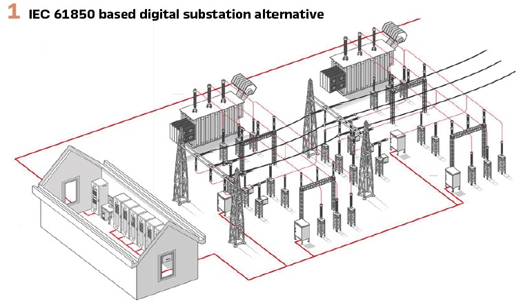
Within medium voltage switchgear panels, the horizontal exchange of IEC 61850-8-1 GOOSE and sampled analog values IEC 61850-9-2 reduces wiring and potentially accelerates the testing and commissioning. Digitalized technology can now continuously monitor mission-critical functions of high and medium voltage switchgear as well as substation transformers, while performing real-time simulation and diagnostics, ensuring that the pro-active management of the asset’s lifecycle is realized. The increasing amount of data in the substation calls for better solutions to turn this data into actionable information, including that the data is secure, accessible, and properly archived. The latest substation data management and asset health management tools provides a power utility a convenient way to exploit the latest advances in this area.
Digital Substation Design
The high-level engineering workflow required to design a digital substation is defined as a part of the IEC 61850 standard in the substation automation system process. A very basic engineering workflow is shown in Figure 2.
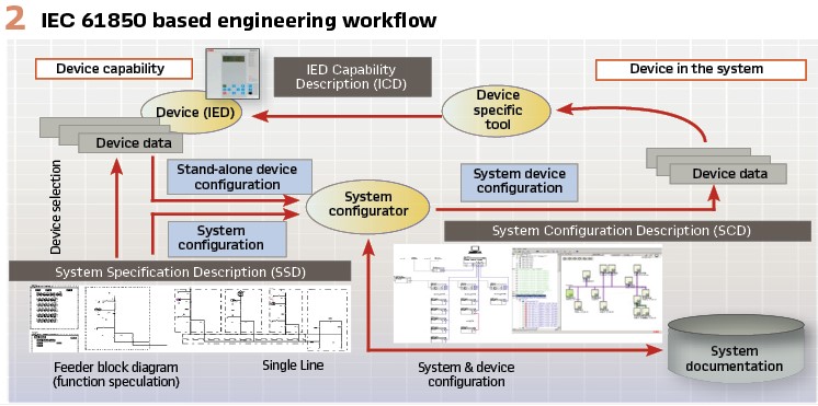
The design process starts with the system specification. Using the appropriate system specification tool (SST), the engineer begins to create the electrical design for the substation. On top of this, the engineer also defines the requirements for the desired network topology, including all the data exchange and function association (allocation of logical nodes (LNs)) using the same tool. The idea behind this tool is to provide a standard-based document which contains all the information for starting the detailed engineering. The output of such a tool is called a System Specification Description (SSD) file which is used as the input file to start the system configuration.
To complete the system design, we also need the individual device descriptions. These files are called the IED configuration description (ICD) files. A vendor neutral System Configuration Tool (SCT) can be used to import all the SSD and ICD files and build the detailed design. Some of the basic information included in this process: data mapping for Bay level (GOOSE) communication, client -server (MMS) communication, and process level (Sample Values) communication, etc. as per the specification. The output of this activity is what the standard calls a System Configuration Description (SCD) file. This is the most important file for our topic of discussion in this article.
Challenge #1 – Getting the SCD correct is a MUST to feed the correct communication exchange data to the Testing Tools for testing the complete PAC Digital Substation.
Digital Substation Testing
One of the biggest benefits to standard-based engineering is that, by the end of such a process we have access to all the engineered information that can be used by other standard compliant tools. Thus, testing such an engineered solution becomes much more simplified than the traditional way of coming up with a divide and conquer approach of doing traditional PAC testing.
Where to start testing:
1. The engineered SCD file. As mentioned before, the SCD file is a critical part of the engineering effort in a digital substation. It contains various sections for data exchange and handling for multiple services like GOOSE, MMS, SV streams, etc. It’s therefore almost inevitable to test the file itself to check the system wide data consistency before even deploying this file into the individual IEDs
2. Once the SCD file gets deployed, it becomes necessary to test the configuration of individual IEDs to check and compare the system consistency for data exchange. This provides a confirmation that the SCD file deployed is working as designed by the engineer. Usually this involves capturing the packets of data that are passing through the network and looking at all the information published as a part of each IED service like GOOSE, MMS, SV, etc.
Challenge #2 – Ensuring that all IED’s with the SCD imported properly perform their functions and that all their services are configured correctly to communicate to the connected substation network(s).
These two tests become the basis for starting the other tests which are traditionally performed during a Factory Acceptance Test (FAT) or Site Acceptance Test (SAT). On a broad scale we can list the activities performed during a FAT or SAT as follows:
1. Functional Tests: Tests performed to validate the settings and the corresponding correct operation of a function
2. Scheme Tests: Tests performed to validate the engineered scheme. For e.g.: Breaker Failure scheme, Line Protection Pilot schemes, interlocking schemes, etc.
3. SCADA Tests: Tests performed to validate the data sent to the SCADA or HMI system. These tests usually involve checking the metered data for scaling issues, testing the alarms and events, switch controls and any outside communication to the Network Control Center (NCC)
In a digital substation, all the above-mentioned tests can be performed in a very fast and efficient manner. (If the SCD is correct.) In the following sections, it is explained in detail how to accomplish each of the 3 tests mentioned above.
Functional Tests
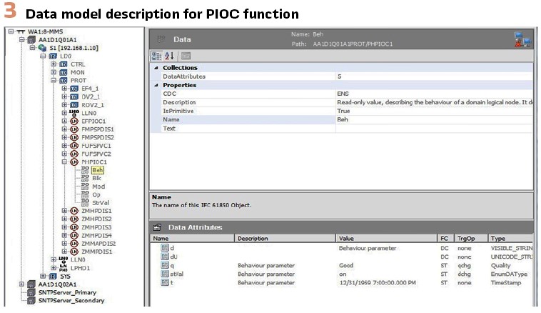
In a digital substation it is very straight forward to test the individual functions. In the SCD file we can drill down to any level required and look at the data specific to the function under test. A simple example of looking at the data model of an instantaneous overcurrent protection is shown in Figure 3. From a testing perspective, all the test plans we traditionally build to test individual protection and control functions can still be utilized. The only change affecting the test plan will be the proper selection of the function’s source(s), (like a SV stream it subscribes), and the selection of the output(s) the function produces, (like an internal “stVal” status bit of its DA (data attribute) or any logic that results in a GOOSE status bit used.
In traditional function testing of a current element, the analog sources were provided by secondary currents generated using a typical relay test set. Today we use Sample Values published by a standards-based, modern relay test set. In the past, the field personnel would use a binary output coming from the IED under test as the trigger condition to stop a test. Today we use a GOOSE message published by the IED with the appropriate data attribute as trigger status to stop the test. The real efficiency comes from the time saved in the preparation for the test and actual time spent to conduct the test and collect the results. Since the test utilizes only known digital signals, there is no need to physically connect, reconnect, or modify individual analog signals as well as trigger signals to the IED. The only connection required is an Ethernet cable connected into the network with proper access for the test set to simulate and monitor the required digital signals.
In a process bus environment, the most critical challenge will be to get the SV streams simulated by the test set working for every test plan as expected by the relay and the test set synchronized to the common system clock just as the actual merging unit. This step is very important to properly test the enabled functions in an IED. As a preliminary check, it’s important to check the Mode and behavior of the functions to be tested in the IED, this has to be done in addition to the test set checks. It ensures the simulated values published by the test set is correct and the test results are in line with the expectation. Fortunately, these checks can be easily performed using test set tools and can be added to the test plan check points. In addition, some vendor IEDs, gives real time access to the current state of every function within and this can be used in parallel with the test set tools that monitor the IEDs while running the test plans.
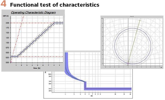
Challenge #3 – Perceived challenges with Process bus testing usually reflects on setting the test plan itself, the rest of the testing is pretty much the same as in a conventional test set environment. (See Figure 4).
Today the standard provides the ability to logically place any individual IED from the system into Test and Simulation mode. This allows the IED under test to “listen” only to the modern test set publishing the test data, without the need to physically isolate the IED under test. The modern test set for digital substations may even be equipped with features to place an IED into Test and Simulation Mode. The entire process of logically isolating the IED, forcing the IED to listen to the test set, perform all the necessary tests within the test plan and then returning the IED to its normal state, can all be engineered into the IED and related test plan, then accomplished quite seamlessly by just a push of a button from the test set.
Challenge #4 – Understanding the IED’s IEC 61850 architecture and configuration to make the translation to the digital inputs and outputs substituted in the functional tests. This is necessary to build trust of the digital processes and services of the IED and trust of the modern test set.
Scheme Tests
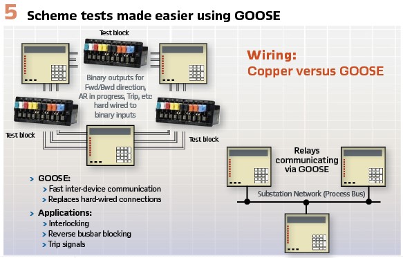
In a Scheme test, more than one IED or used functions may be involved. The same methodology mentioned above can be extended to logically isolate all the IEDs involved in the scheme test using a single test plan executed from the same test set. This is possible because an IED in test mode can communicate with any other IED in test mode according to the standard. During commissioning, some IEDs involved in the protection scheme may not be physically available for testing. Under these circumstances there are tools available that can simulate missing IEDs and can publish all the required GOOSE and Sampled Value messages as defined in the SCD file. Consider a breaker failure condition. If the breaker failure initiate signal is not available, the test plan can include the simulated GOOSE message of the missing IED.
Even if the device is available in the network, by putting the subscribing IED in test and simulation mode, the test set can force the IED to stop listening to the actual IED for the GOOSE message and only subscribe to the simulated GOOSE message from the test set. By isolating the individual IEDs from a network, any scheme can be tested within the same test plan without performing any major changes to the physical infrastructure. This allows SAT tests to continue without waiting on a piece of equipment to physically be available.
The overall time taken to test and commission a substation can be substantially reduced. (See Figure 5).
SCADA Tests
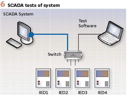
The SCD file which was used to build the communication mapping between the IEDs also contains portions of data mapping required for the SCADA communication. This means SCADA testing can be done in parallel with the relay testing. The same GOOSE messages and Sampled Values that were simulated for the IED testing, can also be simulated to test the SCADA points.
Conversely on the IED side, the testing tools can be used to act as a SCADA and all the SCADA controls can be tested before deploying the actual SCADA at the substation. The test plan can be automated to test each operational scenario and every data point required for the SCADA system.
Challenge #5 – Understanding that the SCD contains all the interlocking and communications of the entire digital substation and that a single test can verify multiple levels of the PAC system.
The SCD file is a complete documentation of the entire system. It gives us a chance to consolidate a lot of the commissioning level test plans to effectively reduce the time we spend on the overall commissioning effort. Trying to test multiple conditions within a single test plan becomes a lot easier in these environments because the effort required is not anything physical, rather just an engineering effort to include all the signals to be published and subscribed in order to get the overall scheme working.
Usually, it comes down to the software constraints of the testing tools used, that will determine how many SV streams and GOOSE messages can be simulated and subscribed simultaneously. In addition, there might also be network constraints, in terms of what information can be published or received with in a particular subnetwork. In many cases, its recommended to assess the Site testing effort individually and come up with a consolidated test plan specific to the network design and test set capabilities and figure out ways to achieve maximum efficiency. (See Figure 6).
Troubleshooting in a Digital Substation Environment
The data model in IEC 61850 has all the information pertaining to the current state of every used function modeled within an IED. Many of today’s modern relay test sets, make it possible to obtain the current state of any function in an IED. In the standard it’s called the Behavior of the logical node. Consider the scenario mentioned under functional testing above, an IED can be put into Test Mode by a test set without any physical isolation or modifications, it’s also equally necessary to validate before starting any test to physically check if the “behavior” of the function has changed. Positive feedback can be used to verify that an IED is in the correct Test or Simulation mode before proceeding with the detailed test plan.
Every message engineered using IEC 61850 has a quality information bit-string associated with it. There are methods and/or tools within the test software that can verify this quality bit according to the standard’s definition and provide visual cues to diagnose the actual validity of the data. This way the testing personnel can focus on the real application related problems rather than interpreting bits and bytes to their actual meanings.
Typical Use Case
Consider a typical 138/13.8kV substation. Assume it has 5 feeders. Each feeder will have a breaker controller, a feeder protection, plus a transformer protection and an overall bus protection for the substation. Typically, it would take roughly 3 days to test and commission this whole substation using traditional secondary injection divide and conquer methods. In the overall time spent for testing these protection panels, 1/3 of it is spent on preparation/connections.
This involves choosing the right sources to be isolated for testing, isolating the correct trips/interlocks and connecting the right cables to the test set. In a digital substation, most of the preliminary work can be done even before arriving at site.
The SCD file for the substation can be used for the test plan preparation which will provide information on what SV streams need to be simulated and what functions are to be tested and what GOOSE messages to be monitored. Another 1/3 of the time is spent on running the actual tests which includes all the functional and scheme tests. With the techniques mentioned above for conducting the Scheme and SCADA test, it is possible to reduce this time by half.
The final 1/3 of the time is spent on troubleshooting and documentation. By automating test plans to document the results and by using all the techniques mentioned above for troubleshooting, it is possible to document every step of the test plan with detailed checks and feedbacks from all the IEDs and complete all the tests in half the time required traditionally.
Challenge #6 – Making the commitment to the IEC 61850 architecture and related standards that create the ability to engineer and test the future of the complete PAC digital substation.
Conclusion
The intent of this article was to clear some misconceptions around the standard that usually lingers with first-time users. Not all aspects of the digital substation are addressed here, the network design, operational procedures, cyber security best practice, just to name a few are not considered.
However, most of the existing accepted processes used for testing and commissioning a conventional substation can be easily adapted for a digital substation. By using automated test scripts, the whole test plan can be organized and automated, and a report can be prepared/published much faster than from a traditional test procedure. Only a few tools have been showcased in this paper to help with troubleshooting, the standard itself has evolved over the last few years and has provided a lot of new features like the LGOS, LSVS and LTRK to online monitor GOOSE, SV streams and all the MMS based services respectively.
There are also Logical Nodes available today to monitor the error statistics of the IED and Switch communications ports which helps with communication supervision for any network topology. There are even tools available today which utilize the built-in features from the standard and provide the users with options to test, commission, diagnose and maintain a digital substation.
To fully utilize the benefits of the standard, a strong importance must be given to the engineering of the digital substation and resulting SCD file using a standard conformant system engineering tool.
Today the standard provides enough conformance guidelines to verify tool compliance. Enough has not been said about the benefits of IEC 61850, in this article we attempt to highlight the usability of the standard itself. It’s a proven global standard that can benefit any utility design.
Biographies:

Bharadwaj Vasudevangraduated from North Carolina State University with a Masters degree in power systems and joined ABB as Protection and Controls Application Engineer. He started his career in power systems with Areva T&D India Ltd. He has engineered and designed various EHV substation projects throughout India. Currently he is working out of New Jersey as the DSS Program Manager for Hitachi Energy. In the last 9 years he has been involved in numerous IEC 61850 projects across North America helping customers go through the digital transformation in their install base.

Jake Groat – received a BS-ECE from Boise State University in 2016. He also completed an AOS in Advanced Aircraft Elec-tronics in 2003 at Westwood College of Aviation Technology. Jake has been working in the energy sector for over 10 years. His current role is Technical Sales Engineer for Hitachi Energy in the Northeast-US region. He is a registered Professional Engineer in Idaho. He previously worked as an avionics technician for fixed wing aircraft and as a radio technician for the maritime shipping industry. He holds a GMDSS Operators and main-trainers license and GROL with radar endorsement.

Benton Vandiver III, P.E. is the Technical Sales Engineer for Hitachi Energy in the Central US located in Houston, TX. He has been in the power industry for 40+ years and with Hitachi for the past seven years. He’s an IEEE senior member, IEEE-SA member, PSRCC member, PSCCC member and past Chair of the P0 – Protocols and Communication Architecture Subcommittee. He is a Digital Substation champion and has authored, co-authored, and presented over 100 technical papers and published numerous industry articles.


