By Christoph Brunner, it4power, Switzerland and Keith Gray, powering, USA
The IOP hosted by UCA: Typically, every two years, the UCA International Users Group organizes the so called IOP or interoperability testing event. The IOP brings together various vendors with their IEC 61850 products, to test the way those products work together. A focus is laid on the latest features in the standard to enhance the maturity of the specifications. During the IOP, based on test specifications that are prepared beforehand, vendors perform tests witnessed by IOP participants from utilities or consultants.
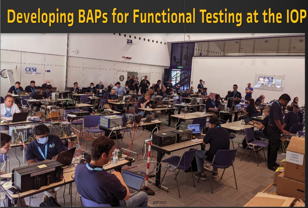
The goal of the IOP is not to pass or fail a test; the goal is to identify issues, that may lead to a failure of a test which uncovers the need to be better specify a requirement in the standard. It is not unusual that already during the preparation of the test specifications, issues are identified.
When we did the first IOP in 2011, the focus was on communication interoperability. Devices exchanged GOOSE messages or reports. Later, the focus shifted to interoperability between engineering tools for the top-down engineering process. Other topics included accurate time synchronization with the PTP profiles and the exchange of routable GOOSE. Issues found during an IOP are classified and may result in improving the specification or improving the conformance test procedures. All that helped to improve the quality of the specifications as well as of the products.
In the recent years, the focus shifted to performing functional testing. In 2017 we designed, for the first time, a layout of a hypothetical substation, where each participating device got its role depending on its capabilities. This allowed us to do functional testing, learning a lot during this process.
We also realized that there are many ways to apply IEC 61850 to model applications. Many devices still used private ways of modeling instead of what is available from the standard. This resulted in a huge effort to engineer our hypothetical substation, as the same application needed a different implementation from one bay to the other, depending on the IEDs allocated to the bay. Also, as the devices were pre allocated to a bay, if one device had troubles, the other devices interacting with that device could not perform tests, until the issues on the first device were fixed.
Functional Testing at the IOP ‘24
Based on experience from the previous years, we decided for the IOP 2024 that, instead of designing one large substation, we design typical bays with typical IED roles allocated to the bays.
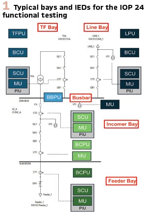
Figure 1 provides an overview on the typical bays and the IEDs for those bays. The IEDs are:
- BCU; Bay Control Unit
- PIU: Process Interface Unit, a combination of Merging Unit (MU) and Switch Control Unit (SCU)
- LPU: Line Protection Unit
- TFPU: Transformer Protection Unit
- BBPU: Busbar Protection Unit
- BCPU: Combined Protection and Control unit
The test scenario will be one of the typical bays, with possible inclusion of devices from the neighboring bays (e.g. for breaker failure protection). To perform the tests, any combination of devices from different vendors, depending on their functionalities, is possible.
The scenarios shall support the following applications:
- Control with interlocking and – where applicable – synchrocheck
- Line and feeder protection with reclosing
- Transformer differential protection
- Differential busbar protection
- Inverse blocking (zone interlock) busbar protection
- Breaker failure protection
The Challenge of the Design during the IOP
As we are planning to do multiple combinations of devices from participating vendors, we will not be able to create the SCD (System Configuration Description) file for all the combinations beforehand. Therefore, we need a process that allows to create SCD file on the fly with reasonable effort.
For that, we have chosen to do a top-down approach, starting with a specification (SSD file) which includes allocation of functions to virtual IEDs. Additionally, to facilitate functional interoperability, we specify the applications using Basic Application Profiles (BAPs). The specification includes all the logical nodes signals required by the BAPs. The specification already includes signal flow requirements for the BAPs. For the implementation, we then need to map the logical nodes on the specific instances in the IED we are using and map the input signals on ExtRefs provided by the IED in case of later binding.
What is a BAP?
Before we get to basic application profiles, we will have a more general look at profiles and the relation between profiles and standards. Why do we need to create profiles for a standard at all? IEC 61850 is designed to suit a large range of applications – from small distribution substations up to large transmission substations and is as well designed to be used in other domains. Therefore, IEC 61850 is a standard with a certain number of optional elements.
This raises a couple of questions: Can we avoid some of the options? What does something that is declared as optional mean? What is the consequence for the vendor that is implementing a product based on IEC 61850? What is the consequence for the end user? Anything that is kind of an option needs some attention by the end user and should preferably end up somehow in a project specification. This may be a time-consuming process and requires some good knowledge of the standard. So that is where the idea of creating profiles was raised.
An IEC 61850 standard profile contains a selection of data models, applicable communication services, and relevant engineering conventions (based on the Substation Configuration Language SCL defined in IEC 61850-6) for an application function of a specific use case in the domain of power utility automation.
In 2019, WG 10 published a “Guideline for definition of Basic Application Profiles (BAPs) using IEC 61850” as IEC TR 61850-7-6. This technical report provides the following definition for a BAP:
User / user group agreed-upon selection and interpretation of relevant parts of the applicable standards and specifications, intended to be used as building blocks for interoperable user / project specifications.
A Basic Application Profile (BAP) is based on system / subsystem specific basic application functions descriptions. The term “basic” means here that an elementary application function / subfunction is the chosen context for defining the profile. The level of what is perceived as elementary is application dependent and may include for example many Logical Node (LN) instances of many LN classes, when using IEC 61850.
A BAP is a selection and interpretation of relevant parts of the applicable standards and specifications describing, how the basic application shall be implemented using IEC 61850. BAPs in IEC 61850 include the specification of signal flow between the functional elements participating in the application.
Applications and Functions
To understand the way a BAP is defined, it is important to understand how IEC 61850 differentiates between applications and functions. An application can be described with one or multiple use cases. The use cases are realized by functions exchanging information. In the world of IEC 61850, a function may be hierarchically decomposed. A function at the lowest level is implemented in one IED (Intelligent Electronic Device) and is associated with an IEC 61850 Logical Node. An application uses multiple functions and can be implemented with multiple IEDs. On the other side, a function may participate in multiple applications.
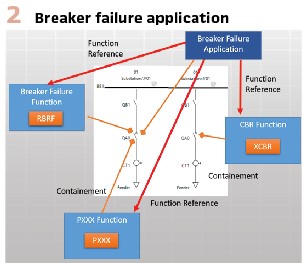
This is illustrated in Error! Reference source not found for the breaker failure application. The breaker failure application starts with a protection trip from any protection function. That trip starts the breaker failure function, which will monitor the breaker opening. For that, the function gets data from the circuit breaker interface function and optionally also from the current measurement function. If the breaker failed, the breaker failure function will trip the neighbor breakers through the circuit breaker interface function. (Figure 2).
Each of the functions participating in the breaker failure application may also participate in other applications as well. As an example, the circuit breaker interface function participates in a protection application as well as in circuit breaker control function.
Developing the BAPs for the IOP 24
As we have seen in the presentation of the BAP, a BAP provides a detailed breakdown of the model and the signals exchanged. Thais is the main reason we chose the approach to specify our IOP requirements through BAPs. This way, every device will have the same modeling approach, which makes integration easier.
The first edition of the TR IEC 61850-7-6 defined a method to describe BAPs in a textual way. Key elements are:
- A description of the functionality
- Description of the use case with the associated actors and functions
- Logical architecture
- Allocation variants
- Functional variants
- Data model per function
- Communication services used for the information exchange
When defining BAPs, it may not always be straight forward to define the scope of the BAP. What is “basic” in a specific context? We should not be too strict with this – a BAP is used to express, how an application shall be realized. The scope of an individual BAP shall be defined pragmatically to best fit the purpose.
For the IOP 24, we define one BAP for each of the applications we have identified (see list presented earlier in the clause introducing the functional testing at the IOP). As an example, we decided, to combine line and feeder protection together with the reclosing application in one single BAP. Of course, another approach would have been, to define one BAP for the protection tripping only and another for reclosing.
Depending on how the scope is defined, a function may be part of the BAP, which means it is described in detail with the function specific signal flow, as is the case for the Protection and Reclosing BAP. Another option is, to model a part of a function only as external actor with a specific signal. This has been done for the breaker failure application, where the protection trip is defined as an external actor interacting with the use cases.
BAP Example from IOP
In the following, the BAP for Protection Trip and Reclosing, as it has been defined for the IOP, is provided as an example.
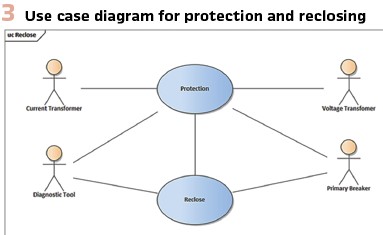
Figure 3 shows the use case diagram. Actors are primary equipment like voltage transformer, current transformer, and the circuit breaker. For the IOP BAPs, we also included an actor for a diagnostic tool which shall receive various information to diagnose test results and record them.
The use cases are realized with the following functions:
- Breaker Interface
- CT Interface
- VT Interface
- Line Protection / Feeder Protection
- Breaker Trip Conditioning
- Reclosing
The interface functions are functions that are typically shared with other applications.
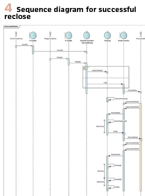
The behavior of the application with the signals exchanged between the functions is described with sequence diagrams for different scenarios. For the protection trip and reclosing, we describe two scenarios:
- Successful reclose after trip
- Reclose on fault and final second trip
The example for successful reclose is provided in Figure 4.
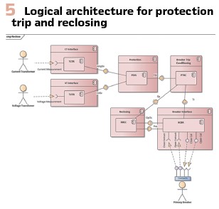
The logical architecture is described as a UML component diagram and is shown in Figure 5 for the line protection. For feeder protection it looks similar, except the LN for the protection element is a LN PTOC and there is no VT interface.
Next, allocation variants are discussed. Allocation variants account for having different options when placing functions inside of physical IEDs. For the IOP, we try to have as few allocation variants as possible.
For the protection and reclosing BAP, in the preferred allocation variant, Breaker interface, CT interface and VT interface functions are realized in a PIU; all other functions in the LPU. If a protection should not support reclosing, the reclosing function could be allocated to a BCU.
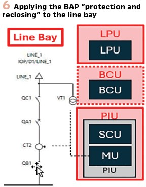
This BAP can be applied to the line bay and to the feeder bay. Figure 6 shows the devices involved when applied to the line bay. As discussed above, the BCU may or may not be involved based on the allocation variant used.
With then decided to not support any functional variants. Functional variants would account for different implementations of functionality within the scheme. We only support one single reclose cycle and three phase tripping.
This is defined by the following parameter settings in the LN RREC:
- RREC.UseCyc.setVal = 1
- RREC.CycTrMod.setVal = 1 (3 phase tripping)
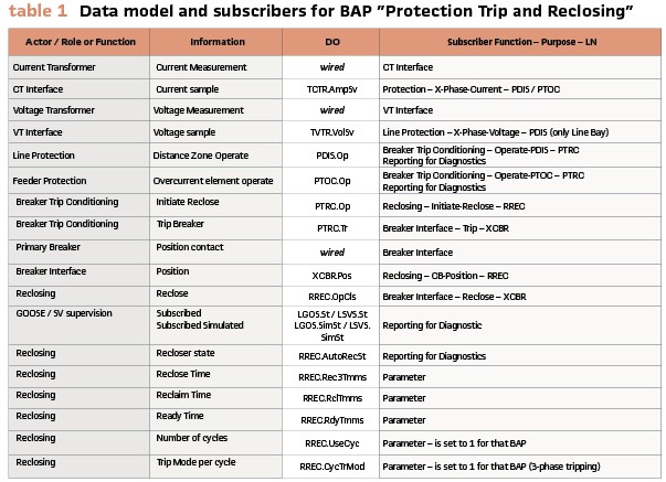
The detailed data model is shown in Table 1. Only signals that, based on function allocation, are between devices are listed. Additionally, signals to be consumed by a diagnostic tool for test documentation and analysis are listed as well.
Lessons Learned from Creation of BAPs for IOP
During the preparation of the BAPs, we found a couple of issues related to modeling applications and functions, where we suggest that IEC TC57, working group 10 discusses them and possibly provides modeling recommendations.
The first issue is the modeling of a lockout relay. That has already been discussed by the North American user feedback taskforce and it has been acknowledged that clarification is required. It will be addressed by WG 10 as part of the work to generate a second edition of IEC 61850-7-500 – a technical report providing guidelines on modeling applications for substations.
A second issue that created lots of discussions during the preparation of the BAPs, was the usage of the LN PTRC (Trip conditioning). There are many different views on where we should place a PTRC – so we suggest that WG10 provides some recommendations on that topic.
A third topic was related to modeling the protection for a bus tie in a scheme with reverse blocking. Shall there be two PTOC for each direction or one PTOC and on RDIR or anything else.
Creating Requirements from the BAP
Based on the BAPs, we can define the requirements on the devices participating at the IOP. As an example, a line protection unit (LPU) will participate in the following BAPs:
- Protection trip and reclosing
- Breaker failure
As part of those BAPs, the LPU needs to support the following functions:
- Line protection
- Breaker trip conditioning
- Reclosing
- Breaker failure detection
- Breaker failure trip conditioning (for external trips received from breaker failure functions in other bays)
This can then be further broken down in data objects to be supported and in signal inputs required.
As part of the preparation work for the IOP, we prepared an excel table that the participating vendors must fill in for each device they plan to bring to the IOP.
There, the functions supported by a device must be selected and the logical node within the data model of the device that implements this function shall be indicated. Signals not supported directly need to be identified and if other signals shall be used this shall be indicated. In the future, such information can be expressed formally in the so-called process icd according to the future TR IEC 61850-90-30.
If a vendor supports later binding, he also shall fill in the information on the ExtRef to be used for a given signal input.
That information will facilitate an efficient production of the system configuration files (SCD) at the IOP based on the specification files (SSD).
Test Scenarios and Test Specifications
Based on the functions defined in the BAPs, we can define a set of tests performed for each bay type. For the line bay, this will be:
- Control with interlocking and synchrocheck
- Line protection with reclosing
- Breaker failure protection
To do those tests, we require the devices as shown in Figure 7.
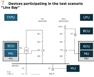
The devices in the line bay are the main devices participating in the test. The devices in the transformer bay are used for the breaker failure function to do the external trip in case the breaker of the line bay fails.
It is planned to do multiple tests in parallel – different bay types or same bay types with different devices. So, a network infrastructure is required that allows to configure multiple independent networks.
Tests with Virtual Isolation
It is also planned to do tests verifying the concepts to be applied when testing a device in a real-life substation.
As an example, the LPU may be isolated from the rest of the system. We then can test the protection trip and reclosing as well as breaker failure. The rest of the system should not be affected.
While the LPU is virtually isolated, a control with synchrocheck shall still be possible; the sampled value message from the merging unit is still received by the BCU although there is a second message on the network from test equipment to perform the tests of the LPU.
SCD Engineering
As mentioned in an earlier section, a SSD file was created based on the BAP requirements. This SSD file will be used, in combination with the ICD/IID files provided by the vendors, to engineer the various SCD files to be used during testing. As an example, when testing the line bay, a SCD file will be needed that contains the LPU, BCU, PIU (containing the line SCU and MU). It will also require the bus MU, TFPU, and HV transformer PIU (containing the SCU and MU). To build this SCD file, a selection of devices submitted by the vendors are chosen, based on the capabilities, to fill each of these roles.
With the devices identified, the associated ICD/IID files are imported into the System Configuration Tool (SCT) where the logical node and signal mapping is completed. In the simplest case, there is a one-to-one mapping from implementation to specification. In other cases, customization may be required based on the functionality and model of the chosen IED.
At least one SCD file including a given device will be created prior to the IOP event.
This gives the vendors time to properly configure their devices and perform any preliminary testing. It also gives the network vendors a chance to build the required network configurations to support each of the tests.
Additional SCD files may be created “on the fly” at the IOP if there is time for additional tests.
All of this engineering work is made possible by clearly defining the system in BAPs.
Conclusion
Basic application profiles are a good concept to describe the modeling of applications. If they are used to define requirements on the devices implementing the functions, interoperability on application level can be achieved using a standard design without the need to customize for individual modeling variants.
With the new approach to functional testing at the IOP, we hope to perform more tests than in previous years. To ensure the devices that plan to participate in the tests are ready, we will create a configuration beforehand and verify the device configuration with a unit test before integrating a device in the interoperability tests.
Biographies:
Christoph Brunner is the President of his own independent consulting company it4power LLC based in Switzerland. He has over 40 years of experience with knowledge across several areas within the Utility Industry and of technologies from the Automation Industry He has worked as a project manager at ABB Switzerland Ltd in the area of Power Technology Products in Zurich / Switzerland where he was responsible for the process close communication architecture of the automation system. He is Convener of WG 10 of the IEC TC57 and is a member of WG 17, 18 and 19 of IEC TC57. He is senior member of IEEE-PES and IEEE-SA. He is an IEEE Fellow and is active in several working groups of the IEEE-PSRC and a member of the PSRC main committee and the subcommittee H. He is advisor to the board of the UCA international users group.
Keith Grayreceived his B. Sc. And M. Sc. Degrees in Electrical Engineering from Southern Illinois University Edwards-ville in 2003 and 2005, respectively. Since graduation, he has been working at POWER Engineers, performing SCADA, protection, and automation design and commissioning projects. His areas of interest include digital substations and IEC 61850. He is currently participating in a Cigre B5 working group as well as contributing to IEC TC57 WG10 standards. He is a licensed Professional Engineer in Idaho.


