By Richard Marenbach, OMICRON electronics, Germany
Operators of electrical power systems face three big challenges nowadays. The transition from carbon-based generation to renewable generation will bring a huge transformation of electrical power networks. More new power plants than ever before have to be commissioned and put into operation in the same amount of time. New technologies will lead to more and more assets becoming an intelligent electronic device or being virtualized completely. This will increase the number of firmware-updates drastically. Additionally, we can observe an increasing shortage of skilled workers in many countries.
Thus, operators of electrical power networks are highly recommended to review, rethink and partially redesign their workflows and react to the new conditions. Especially the phase of operation and maintenance uses many resources today. Therefore, this paper presents two examples on how to solve these challenges with a systematic approach.
Life Cycle of an IED and Appropriate Testing Scenarios
A digital protection relay or intelligent electronic device (IED) undergoes many different tests during its life cycle. Starting at the manufacturers site, over engineering, commissioning, and maintenance. all tests have their own purpose, so different testing methods and scenarios are needed to check the correct behavior of the IED or protection system. Every testing scenario of an IED should be seen as part of an integrated testing process.
A harmonized testing process is characterized by efficiency, high quality, transparency, comprehensiveness, and well-defined responsibilities of staff.
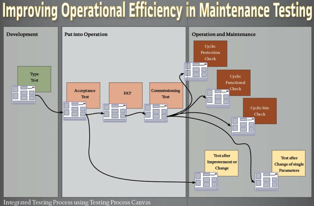
In 2022, associations in Central Europe published a guideline for the test of IEDs that covers all phases where the IED is under responsibility of the grid operator. This structure can be extended by a first phase where the IED is under development by the manufacturer. So, the overall life cycle can be divided into three main phases: “development,” “putting into operation” and “operation and maintenance” (neglecting the phase of decommissioning). Each of these phases can be further divided into specific sub-phases (refer to Figure 1). In all these phases different testing methods and testing scenarios are needed to ensure the appropriate behavior of the IED or protection system.

The aim of Testing
Before testers start to design the testing process, they should reflect what the purpose of a test scenario is: the test should prove that the device under test (DUT) or system under test (SUT) shows its nominal behavior. For the following paper we suppose that DUT and SUT are equivalent. It should be clear that the nominal behavior of the DUT has been defined before the test scenario is designed. Furthermore, it also should be clear, that every test scenario should deliver additional information about the DUT, which means conversely that every test scenario that delivers not an additional information about the behavior of the DUT is not necessary and a waste of time.
The testing process should be seen as a continuous process along all phases in the life cycle of the IED with different interdependencies. Based on Figure 1, different test phases can be defined. Every fault in the protection system wiring faults should be discovered at its earliest possible phase. Every undetected fault can be the reason for misbehavior of the protection system and will go hand-in-hand with higher costs for later fault elimination.
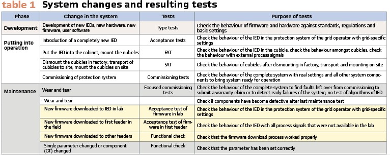
Table 1 shows which changes an IED or protection system can undergo during its life cycle. Every change can’t be the trigger to test the actual behavior against the nominal behavior.
Developing a Systematic Test Approach with the Testing Canvas
As we have seen, different testing purposes require different testing methods and scenarios. The different testing strategies might follow different corporate strategies, but the answers on the questions “Why are we testing?” “What are we testing?” and “How are we testing?” should be done always based on the same methodology.
This might be complicated, so for an easy approach a testing process canvas – like a business model canvas – has been developed that covers all necessary topics that should be considered when designing a new testing procedure, (refer to Figure 2).
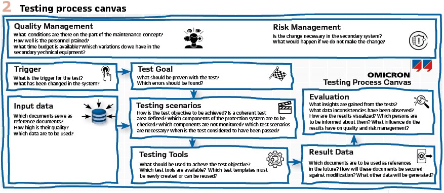
The user is guided through the development of the testing process with dedicated questions. They have a very general character, but the answers can be completely different from company to company. By this way, it is possible to generate the most efficient testing scenarios for all testing purposes with a high quality, minimum number of test shots and defined responsibilities.
As a basis it is necessary to decide in a risk and quality management step if the test is required or not and what could happen – how the risk of failure will increase – if the test is not done. A more detailed description will follow later in example 1. Before any test scenarios are developed, all preconditions must be noted as for example team size, team knowledge, variety of different IEDs, number of IEDs, quality of internal standards and many more.
The first step should describe what changes have or could have taken place in the protection system. These changes are the basis for specifying the testing goal and which kind faults we want to find and what should be proven with the testing scenarios. This approach serves as a preventive measure, reducing the costs associated with extensive troubleshooting. For instance, addressing a faulty configuration before its implementation in substations can pre-emptively resolve issues. It is crucial to emphasize that the purpose of identifying necessary fault scenarios is not to search for faults in the protection system that may have not been discovered in prior tests. Therefore, during maintenance testing, the objective is not to find faults that linger from the commissioning phase. However, some utilities use the first test after commission to detect early failures of components to make warranty claims against the contractor, if necessary, which also makes sense (refer to Table 1).
In the next step, the input data to develop the test scenarios must be evaluated. In particular, the data quality of the used documents (files, diagrams, …) must be assessed. This is necessary because the input data build the testing reference, therefore we must trust in them (as single source of truth). Testing makes only sense if we have a testing reference and if the testing reference has a high quality. In other words, testing is the comparison of a requested behavior with the actual behavior to evaluate the deviation. If the reference has a low quality, it makes no sense to build up test scenarios because the result of testing cannot be better than the reference.
Developing test scenarios means to determine the test cases that must be performed to reach the testing goals. As we do not want to lose time with inefficient testing, we concentrate on test scenarios where each test case delivers a new information about the behavior of the protection system. A test case can be a single shot using the test equipment or can be a longer lasting simulation with dynamical behavior.
In the next step we have to define all components of the protection system which belong to our testing scope. Components which are “out of scope” can be neglected completely. If components of the protection system are monitored by another instance, these components can also be excluded from our list of components to be tested. It must be discussed individually how the self-monitoring capabilities of the IEDs are used and if specific test cases for these elements have to be developed. With this description a collection of test scenarios can be worked out.
The goal is always that every component of the protection system is only tested once. Sometimes testers like to stimulate a digital distance protection relay with hundreds of shots into Zone 1 during maintenance test. This kind of testing makes sense during acceptance testing in a very early stage of the life cycle but has nothing to do with an efficient testing process during maintenance. When the whole collection of test scenarios is ready, a look onto the needed testing equipment is appropriate.
It is useful to determine which test templates for automatic testing have to be created from scratch or which test templates from preceding test steps can be used or have to be updated. The usage of test systems that provide templates is always recommended to be able to exactly reproduce the test scenario.
The handling of testing results completes the definition of a testing process. It must be worked out, how the test results will be further used. Some of these data or documents can be used for other testing procedure as their input data and also as reference data (single source of truth).
These data have to be protected against unintentional or intentional changes because then, they would be worthless as reference data. Finally, it must be defined in an evaluation step how the newly gained insights of the protection system and its behavior are used in the whole company. Did we observe data inconsistencies that now should be corrected? Which persons must be informed about the testing results?
Following this methodology, a systematic approach is available that can lead to very efficient procedures with a very high testing quality. It should be mentioned again that test results from one testing procedure could be the input data i.e., reference data for the next testing procedures. By this way, an integrated testing process can be installed in the company (header Figure at the beginning of the article).
The methodology is presented in two different examples. Example 1 handles a new testing procedure for a cyclic protection test, example 2 shows a new testing procedure for a firmware update.
Example 1: A new testing procedure for a cyclic protection test during maintenance: To prove the power of this approach a project with a Transmission System Operator (TSO) in Europe was started. The initial situation was, that the TSO wished to become more efficient during cyclic protection testing which take place every 5 years (blue fields in Table 1). The power system is usually protected by Main1 and Main2 protection on transmission lines.
A normal maintenance test of all functionalities of their protection cubicles normally needed 2 full days. The expressed wish was to review the testing methods and workflows to be able to make all tests in one day. It was agreed that they do not want to take the old test templates from maintenance and delete test shots from them because this would lead mentally to the fact that finally not enough has been tested. The development of testing scenarios should start from scratch and should only cover necessary tests.
Every test case should deliver additional information about the behavior of the protection system. In the first step all preconditions had to be collected and evaluated. It turned out that the utility has a very high standard in their protection cubicles and that the staff is highly qualified. The results presented here, are only based on these preconditions. In other utilities the results could deliver other results.
The goal of this new cyclic maintenance test was that they want to detect changes in the system under the condition that nobody changed the settings or did similar alterations in the system since the last test took place. As reference document the circuit diagram of the protection cubicles was used. With the help of this document, the scope of the system under test was defined. This was done very precisely going down to the terminal block designations.
After discussions it was defined that a parameter comparison between parameter sets downloaded 5 years before and downloaded during the new test is sufficient to prove that the IED has the same settings than 5 years before. Using this method saves a lot of time but should be discussed individually, because testers with lower skills could make many faults during this procedure culminating in inaccurate testing results.
As it was clear that all testing scenarios that “only” prove the correct setting of a parameter are not necessary, it had to be worked out which tests must be applied to cover all possible faults in the protection cubicle. It turned out that all these faults would arise if a wire in the protection cubicle is loose or defective. Some of these wires were monitored by other systems so they also do not have to be considered in the testing scenario. This results in a manageable number of components that must be tested. To proceed in a systematic way, all wires that come from the terminal blocks and go into the IED were listed in a table, doing so with all wires that come from the IED going to other terminal blocks.
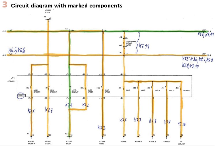
The TSO staff decided how to prove the correct functionality of these components. Therefore, in a first step a 3-phase fault at 50 % of Zone 1 at line angle was defined. All wires that were used during this scenario were marked with a specific color in the circuit diagram (Figure 3). Now it was discussed which next testing scenario will cover most of the wires that have no color up to now. This step was repeated until all components in the circuit diagram had a color, i.e., no component has been forgotten to be tested. In this way a testing template was created that delivers full coverage of the SUT with a minimum number of single test shots. Only 12 single shots plus the comparison of parameters were necessary to cover all wires, interfaces and components of the distance protection cubicle.
As this testing method was radical new, it was clear that not everybody had a full trust in it, because the old method was used for many years. It was decided that the testing team is divided into two groups: the first group had to install faults of different kinds in the protection cubicle without telling the other group. The second group had to find the faults with the new test method. All 10 faults in the cubicle could be detected with the new method. When the method was rolled out into the field it turned out that the test of Main1 and Main2 protection could now be done in just a half day. Finally, the new method is 4 times faster than the old one.
Example 2: Setting up a new testing procedure for a firmware update during maintenance:
The number of firmware updates will increase in the next years. Reasons could be that vulnerabilities have been detected, faults in the protection algorithms have been detected, new functionalities should be implemented or compatibilities with other components should be established. It makes sense, to revise the workflows within the utility to be prepared for the future. Table 1 shows an overview of different testing purposes that also includes the necessary tests for a firmware update (yellow fields in Table 1).

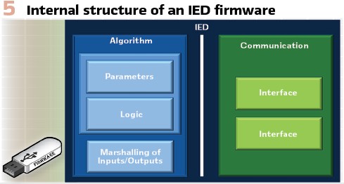
Figure 5 shows a simplified overview of the firmware structure inside an IED. It makes clear that in case of firmware-updates multi-domain considerations by protection and IT/OT-experts have to be done. It could be that the firmware-update is not needed from the protection view but is urgent from the cybersecurity view. The same also applies to IEDs with combined functionality such as multifunctional protection, automation and control devices as they can be found in many industrial or distribution grids. To do the tests in a most efficient way, it is recommended to setup the firmware tests in three stages that build on each other (refer to Figure 4).
Under ideal conditions the grid operator has access to a lab where IEDs and protection cabinets are available for the tests of Stage 1. The purpose of this testing procedure is to check the behavior of the IED in the protection system of the own grid with typical settings. It can be seen as a kind of acceptance test. When you discuss with protection experts in the field, they often say that implementing a new firmware to the IED is equivalent with installing a completely new relay type. The amount of test scenarios that should be applied in this stage could be very high. If there are already testing procedures for acceptance tests in general, many of these testing scenarios could be used which makes the process more efficient. The test scenarios should cover all situations that could be tested in the lab using a high level of test automation. Missing process signals from other system components could be simulated if available. The usage of digital twins can save time also. During this stage the correct order of work steps during the firmware update must be evaluated and written down as a check list for the later usage in the field.
All tests where process signals from other components are needed have to be made in Stage 2 in the field on a dedicated feeder. The number of test cases should be smaller than the number of test cases from the first stage. Only tests which have not been possible in the lab should be made.
In the Stage 3 the firmware is rolled out into all IEDs in the field using the predefined checklists. After the firmware update has been done, only simple final functional checks should be done for efficiency. Utilities also discuss about to test nothing in Stage 3, this could be of interest if automatic firmware download routines are used in the future.
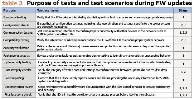
Table 2 shows a proposal what could be tested during the different stages in case of a firmware update. These testing requirements may vary based on the specific characteristics of the IED, the criticality of the application, and the industry standards applicable to the power system. It is recommended to follow manufacturer guidelines and industry best practices when conducting firmware testing.
Unfortunately, the design of these test scenarios for the three stages is not enough to set up a proper workflow. A proposal for a complete workflow for a firmware update is shown in Figure 6.
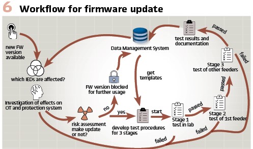
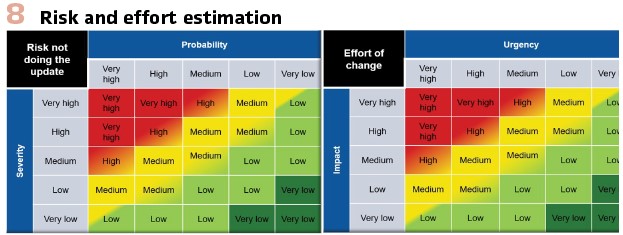
The process starts with the information that a new firmware for an IED is available. How the grid operator gets this information is not a topic here but could be a hurdle for him in real life. It is very beneficial to have a Data Management System (DMS) in place with high data quality to know which and how many IEDs in the own protection system would be affected by the change of a firmware update in the protection system. An interdisciplinary team of IT/OT and protection specialists has to evaluate if it is necessary to implement the new firmware or not to implement it. This could be done using a “risk-of-not-to-change”- matrix which covers the values probability and severity of an unwanted event in case the change in the system is not done (firmware is not applied) and with a second matrix that evaluates the “effort-of-change” and covers the values impact and urgency when the change in the system is done (firmware should be rolled out to the field), (refer to Figure 8).
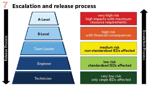
According to their own quality management procedures the company should develop a system of responsibilities on “who has to decide what” along the internal hierarchy of the company. If only a single IED is affected and the effort to change is low (the battery of the IED has to be changed), a technician can decide on its own responsibility how to proceed with the change and the necessary tests. If the effort is high because all IEDs in the grid are affected of a firmware change and not enough manpower is available, it could be necessary that the management from first or second level has to decide how to proceed (refer to Figure 7).
If the decision is not to roll out the new firmware, this firmware version has to be blocked for further usage in the DMS. (refer to Figure 6).
After the decision to go for the change, the start of the testing procedures can happen for all three stages. It is useful to have a dedicated DMS that can deliver the accurate information at the right time where also the results of all testing procedures can be saved without losing any information. It is also the right place to store templates and the documentation for the overall working process. An additional topic has to considered: what should happen if the tests in Stage 1, Stage 2 or Stage 3 fail. A solution could be that the team of specialists is involved to discuss and decides about the next steps to further roll-out the new firmware or inform the manufacturer about the found issues.
Embracing change, adopting systematic approaches, and fostering collaboration are crucial elements that will contribute to operational efficiency in maintenance testing of digital protection relays. The goal is to enhance the adaptability, efficiency, and overall effectiveness of processes to foster the challenges of the future.
Biography:

Dr.-Ing. Richard Marenbach, IEEE, after getting his diploma in electrical power systems in 1990 from Technical University of Kaiserslautern, Germany he was an assistant of the technical director of a local utility. From 1994 until 1998 he was a research assistant at the institute for electrical power systems at Technical University of Kaiserslautern. He got his Ph.D. with a research work about optimized testing of digital distance protection relays. From 1998 until 2000 he was working as a consultant at the association of electrical power utilities in Germany. In 2000 he joined OMICRON. He is process manager of Engineering Services of the Business Unit for Secondary Assets.


