by Edmund O. Schweitzer, III, Veselin Skendzic, Yanfeng Gong, Armando Guzman, Mangapathirao V. Mynam, and Jean Leon Eternod, Schweitzer Engineering Laboratories, Inc, USA
Traveling-wave-based protective relays with high-resolution megahertz sampling capability have recently opened a new window into the high-voltage transmission system operation. Continuously available (24/7), these relays keep constant watch over the power system, recording large numbers of transient events that were previously unknown.
Over a two-year recording campaign, we collected over twenty thousand event records. Events span almost all application and voltage levels, from monitoring a 765 kV transmission network, down to analyzing a 13.8 kV shunt reactor switching transient
This article presents selected events along with system data and detailed analysis. Of special interest are the events that did not lead to breaker trips, because they could be used proactively for predictive maintenance. Repetitive events from the same geographic location may be indicative of failing electrical equipment, a contaminated insulator, or a failing instrument transformer.
Events from the same geographic location may also indicate severe lightning activity in a specific location and warrant improving shielding for power lines in the area. Utilities are interested to learn if they can use such precursors to justify implementing preventive measures.
Fault Current Interruption
We begin by analyzing a high-resolution event record documenting the B phase-to-ground fault on a 161 kV line in Idaho. The event was captured with a relay that samples voltages and currents at one MHz with 18-bit resolution; this relay can record up to 1.2 s at this rate. The line is operated by the Bonneville Power Administration (BPA) and is 117.1 km (72.7 mi) long.
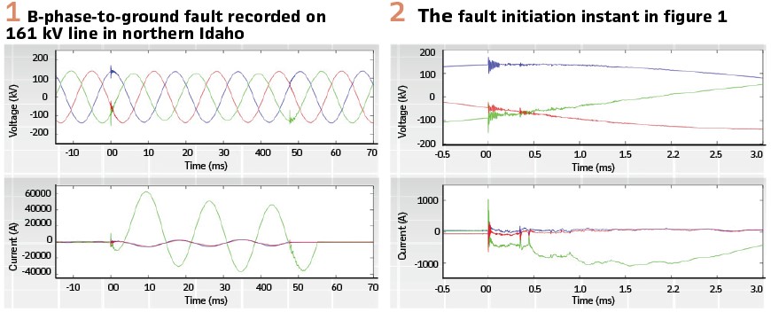
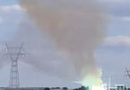
At the time of the event, operators reported storm activity in the area. Figure 1 shows the waveform collected during the fault. It is easy to identify the initial fault transient as well as the current interruption clearing the fault.
Two of the phases were cleared in slightly over 2.5 cycles, with the B-phase event lasting over 3 cycles. One thing that immediately stands out is a set of high-frequency transients present in the last half cycle of the fault (B-phase).
Magnifying the initial fault transient in Figure 1 gives us Figure2. Using this high-resolution waveform information, we can isolate the TWs and identify the fault location as 65.5 km (40.71 mi) from the terminal.
A detailed inspection of the current waveform recorded before the fault, as shown in Figure 3, allows us to identify the cause of the fault.
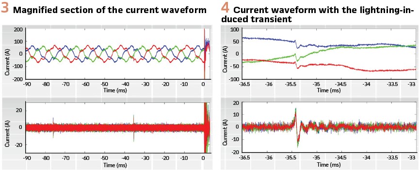
Figure 3 shows the pre-fault current and its high-frequency content as observed through a differentiator-smoother TW extraction filter. The waveform allows us to identify two precursory events occurring at approximately 76 ms and 35 ms before the fault. Magnifying one of the precursory events, as shown in Figure 4, we see a common mode current transient with the same shape on all three phases.
This signature is characteristic of a lightning-induced transient caused by an approaching storm with strikes in the immediate vicinity of the line.
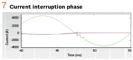
Now that we have a high confidence that this fault was caused by a lightning-induced flashover, we can focus our attention on the current interruption and the high-frequency transient visible at the end of the event, as shown in Figure 7.
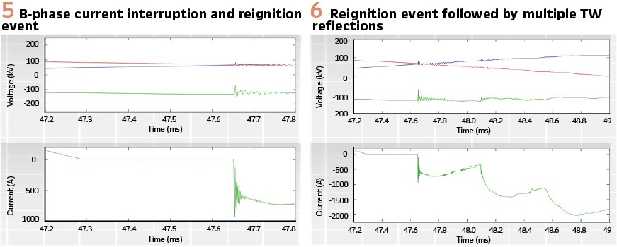
A-phase and C-phase opened cleanly, with the B-phase reigniting 360 μs after the interruption at the previous current zero. Figure 5 shows the B-phase reignition detail.
Figure 5 shows that the B-phase voltage was very close to its negative peak (–130 kV) at the time of the fault current interruption. As with most of our recordings, it is important to note that the current measurements are typically very faithful and show a broad frequency response, while the voltage measurements show filtering and internal resonances caused by the VT construction. In the case of this particular event, the voltage was measured using the bus-connected “magnetic” (traditional) VT.
With the VT connected to the bus side of the breaker, it may be somewhat surprising to see the relatively modest size of the recorded voltage transient.
However, we need to keep in mind that the VT filters all waveforms and that the VT location on the bus side made it impossible to see the line voltage leading to the reignition event. Looking at a slightly broader view (Figure 6), we can see several TW reflections initiated by the reignition event.
We start by referencing the Figure 6 reignition transient shown at 47.65 ms as time zero. This transient travels to the previously identified fault location (65.5 km), which is still fully ionized given the short time since current interruption. The transient reflects from the fault, reaching the breaker 445 μs later. Reignition itself is normal, simply indicating that the B-phase contacts did not have enough time to part. Activating the breaker coil several milliseconds earlier may have been enough to prevent this reignition event.
Transmission System Health Monitoring
Better understanding of the substation electromagnetic environment is one of the less expected benefits of the high-frequency TW technology deployment. Over the course of this study, we confirmed that high-voltage (HV) and extra-high-voltage (EHV) substation measurements obtained using conventional instrument transformers, normal secondary wiring, and standard substation construction practices were exceptionally clean and generally noise free.
However, the electromagnetic environment can change very rapidly. Let us analyze an event recorded on a 765 kV system operated by American Electric Power (AEP), with a single megahertz relay pilot in place at a substation in northwest Ohio, referred to as Substation 1 in this article.
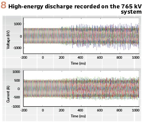
The corresponding recording is shown in Figure 8, Although unexplained at first, this event was soon followed by a set of three events recorded within a 15-minute interval.
The first two events in the group show the sudden appearance of very strong arcing, as shown in Figure 9 and Figure 10.
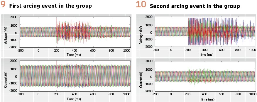
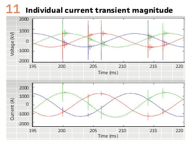
The voltage waveforms shown in Figure10 were especially troubling to AEP engineers because the relay inputs were temporarily overloaded with the last-known measurement point, apparently reaching 1800 kV. The high-voltage reading is normal because the VT ratio at high frequencies is determined by the parasitic capacitance and has no relationship with the official nameplate rating of the device. However, the magnified portion of the current waveform shown in Figure 11 is more troublesome, suggesting current transients in excess of 1 kA.
The actual break in our investigation came from the last event (see Figure 12). This event is much simpler, showing three distinct transients, with a timing pattern that is consistent with a typical breaker closing signature.
To identify this event, we contacted the AEP team and requested the SCADA alarm log for the same time period. The SCADA log is shown in Table I.
The last entry in Table I clearly shows that the event in Figure12 captured the energizing of the shunt reactor, RA1, located at the Substation 1 bus. Knowing the exact location of this event was crucial for our effort to identify the location of the preceding two events. Being limited to a single relay location, we decided to compare the TW reflection signatures of the three events.
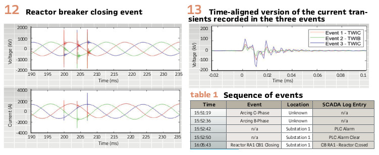
We started by isolating the current waveform of the active phase for each of the events and carefully aligning those waveforms in time, as shown in Figure 13 below. Our first surprise was the striking similarity of the current wave shapes. By adjusting the time scale, as shown in Figure 14, we could visualize the TW signature associated with these events.
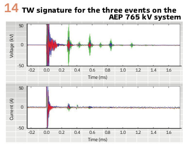
The voltage channel gain that caused clipping in Figure 10 became helpful in this case, providing additional sensitivity and magnifying the recorded TW amplitude. To our surprise, the TW signature for the three events was an exact match, allowing us to conclude that all three events originated at Substation 1 and were closely related. Figure 14 shows multiple reflections from the bus that is 39.7 km away, multiple reflections from the tap that is 60.6 km away, and a reflection from the line end that is 243 km away. TW reflections positively confirm that these are primary system events.
The only mystery remaining to be solved is what caused these transient events. The recorded events have the following characteristics:
- Appear suddenly
- Begin on C-phase
- Spontaneously die out
- Appear on B-phase approximately 1 minute later
- Precede breaker closing by approximately 13 minutes
- Originate at the same bus
- Are characterized by very short transients
- Are energetic enough to travel very far into the 765 kV system
Based on these characteristics, we concluded that the high-frequency transients recorded at Substation1 were caused by the disconnect switch operation connecting the high-side of the shunt reactor breaker, CB1, to the 765 kV system. The fast high-current transient surge phenomenon is well documented in the industry. It is known to cause fast transient overvoltage and is normally associated with operation of gas-insulated switchgear (GIS) disconnect switches. The AEP installation uses air-insulated disconnects. These are located between 15 and 20 meters from the GIS breakers, which may lead to somewhat lower transient frequencies. The PLC alarm reported by the SCADA system further corroborated the presence of these transients.
AEP is very interested to find the cause and actual magnitude of these high-frequency transients and understand the impact that these transients have on surrounding primary equipment, such as transformer windings. Currently, AEP is pursuing high-bandwidth instrument transformer technologies with megahertz sampling capability in order to gain more insight into power system fast transients as reported in this article.
Our investigation continues, but results collected to date clearly show the preventive maintenance potential of megahertz technology-based system health monitoring and the practical value of continuously monitoring the substation electromagnetic interference environment.
Conclusion
Relays with megahertz sampling capabilities are providing valuable new insights into power system operation. Precise time synchronization, high-accuracy, and high-memory capacity are being combined to obtain event records with an increased level of detail.
Every new tool provides new insight and potentially a new set of worries for the system operator that was unaware that certain transients were present on the system. Widely deployed, new megahertz-capable tools are allowing us to improve condition-based monitoring and giving us the ability to proactively attack potential problems before they occur.
Properly applied, we expect the new tools to bring the reliability and availability indices of our transmission network to a whole new level.
Biographies:
Edmund O. Schweitzer, III president and chief technology officer of Schweitzer Engineering Laboratories, Inc. (SEL), is recognized as a pioneer in digital power protection. He is an IEEE Fellow and a member of the National Academy of Engineering. Dr. Schweitzer has received numerous awards from universities and industry associations, including four honorary doctorates and the 2012 Medal in Power Engineering, the highest award given by the IEEE. In 2019, Dr. Schweitzer was inducted into the National Inventors Hall of Fame for his invention of the first digital protective relay. He has written dozens of technical articles and holds more than 200 patents. Dr. Schweitzer received his bachelor’s and master’s degrees in electrical engineering from Purdue University, and his doctorate from Washington State University. In 1982, he founded SEL to develop and manufacture digital protective relays and related products and services for electrical power systems.
Veselin Skendzic is a principal research engineer with Schweitzer Engineering Laboratories, Inc. He earned his BSEE from FESB, University of Split, Croatia; MSc from ETF, Zagreb, Croatia; and PhD from Texas A&M University, College Station, Texas. Veselin is an IEEE Fellow, has written multiple technical articles, has over 25 patents, and is actively contributing to IEEE and IEC standard development. Veselin is a member of the IEEE Power Engineering Society (PES) and the IEEE Power System Relaying Committee (PSRC).
Yanfeng Gong received his BSEE from Wuhan University, China, in 1998, his MSEE from Michigan Technological University in 2002, and his PhD in electrical engineering from Mississippi State University in 2005. He worked as a research engineer at Schweitzer Engineering Laboratories (SEL), Inc. from 2005 to 2013 and as a principal engineer/supervisor at American Electric Power (AEP) in the Advanced Transmission Studies & Technologies (ATST) department from 2013 to 2019. Since 2019, he is a senior engineer at SEL. He is a senior member of IEEE.
Armando Guzman received his BSEE with honors from Guadalajara Autonomous University (UAG), Mexico. He received his Master of Science and PhD in electrical engineering and master’s in computer engineering from the University of Idaho. He served as regional supervisor in the Western Transmission Region of Comisión Federal de Electricidad for 13 years. Since 1993 he has been with Schweitzer Engineering Laboratories, Inc, where he is a distinguished engineer. He holds numerous patents in power system protection, metering, and fault locating. He is a senior member of IEEE.
Mangapathirao Venkat Mynam, received his MSEE from the University of Idaho in 2003 and his BE in electrical and electronics engineering from Andhra University College of Engineering, India, in 2000. He joined Schweitzer Engineering Laboratories, Inc. (SEL) in 2003. He is presently working as a principal research engineer in SEL research and development. He was selected to participate in the U. S. National Academy of Engineering (NAE) 15th Annual U. S. Frontiers of Engineering Symposium. He is a senior member of IEEE and holds patents in the areas of power system protection, control, and fault locating.
Jean Leon Eternod, is the technology director for Schweitzer Engineering Laboratories, Inc. (SEL) for Latin America region. Prior to joining SEL in 1998, he worked for the Comisión Federal de Electricidad (CFE) power systems studies department for transmission systems. From 1991 to 1998, he worked with wide-area network protection schemes; single-pole trip and reclose studies; and database validation for short circuit, load flow, and dynamic simulation. He received his BSEE from the National Autonomous University of Mexico (UNAM), where he also completed postgraduate course work in power systems. He has authored numerous technical articles.