by Mark Adamiak, Adamiak Consulting LLC, USA
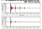
With the digitization of the power system, new numerical devices were able to provide a digital record of the events and waveforms seen by the device. Early on, it was recognized that it would be desirable to have a common file format from these devices that could be shared and viewed with data from other devices (see Figure 1).
To facilitate the goal of a common file format, in 1991, the IEEE Power System Relay Committee (as it was known in 1991) created a “standard” file format which was named the Common Format for Transient Data Exchange or COMTRADE. The original COMTRADE document was based on the common practice that files were stored on 3.5” Discs that could only contain 1.4 MB of data and where file names were limited to 8 characters.
As technology changed, the standard evolved with revisions of the standard in 1999 and 2013.
The Utility Industry is now in the midst of another technology advancement – driven to an extent by the general adoption of the IEC 61850 protocol in the world. Specifically, device configuration is migrating to the eXtensible Markup Language – XML; Process Bus is beginning to take root; users are becoming more computer savvy and look to do more with the collected information. To identify gaps and potential innovations in COMTRADE, a Working Group in the IEEE Power System Relay and Control Committee was established. The WG took a “blue sky” approach to look into the future and to make recommendations for a Next Generation COMTRADE standard. A report identifying a number of potential “upgrades” to COMTRADE was created which includes creation of an XML-based implementation. This article summarizes a number of the changes proposed by the WG.
What is XML?
XML is what is known as a “Markup Language” that defines a set of rules for encoding documents in a format that is both human-readable and machine-readable. Specifically, XML is concerned with the description (the Markup) and structuring of data. The description of the data and the data itself is known as an “element.” Elements are identified by “tags.”
For example, in communicating that a piece of data is a first name, the XML Markup of this information could look like:
<FirstName>Alex</FirstName>
In XML, ALL tags must have a Start Tag and an End Tag.
<FirstName> is the Start Tag and </FirstName> is the End Tag.
The data – Alex – is contained between the tags.
XML allows for creating a hierarchy of tags. For example, a Name could be described as:
<Name>
<First>John</First>
<Middle>Paul</Middle>
<Last>Jones</Last>
</Name>
XML files provide the option of defining a “Schema” for the created XML file. An XML Schema is defined in a file known as an XML Schema Definition (XSD). It is used to describe and validate the structure and the content of XML data. XML schema defines the elements, attributes and data types. Schema element supports Namespaces. It is similar to a database schema that describes the data in a database.
Lastly, for the purposes of COMTRADE, XML provides the ability to create a “Style Sheet” (XSLT) which provides a mechanism for “formatting” an XML document for presentation on a web browser or other viewing device. As such, a Style Sheet could be created to view the Configuration information of a COMTRADE file through any Web Browser.
Overall view of XML COMTRADE
It is proposed that XML COMTADE would follow the same general format of the existing COMTRADE structure but with XML-specific additions. An XML document is called well-formed if it satisfies certain rules, specified by the W3C. An XML document can contain only one root element. So, the root element of an xml document is an element which is present only once in an xml document and it does not appear as a child element within any other element.
Migration to XML allows file validation through the creation of a Schema. An XML Schema is defined in a file known as an XML Schema Definition (XSD).
It is used to describe and validate the structure and the content of XML data. XML schema defines the elements, attributes and data types. Schema element supports Namespaces. It is similar to a database schema that describes the data in a database.
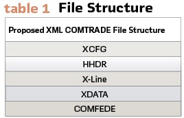
XML COMTRADE would include the following sections:
<XCFG> – which would be the XML version of the Configuration section of COMTRADE (CFG)
<HHDR> – this would be an HTML user-configured web-page containing information about the event
<XDATA> – this would be the time sequence data
<X-LINE> – this section would contain 1-line drawings – created using the 61850 Substation Configuration Language (SCL)
<COMFEDE> – the Common Format for Event Data Exchange – this section would include XML-based Sequence of Events as defined in IEEE C27.239.
Standard XML separators would be used to separate the sections. As such, the Configuration section would begin with the tag:
<XCFG>
And end with the tag:
</XCFG>
It should be noted that the proposal is to have a one-to-one correspond between the existing CFG file and the XCFG file.
Since, by definition, an XML file is composed of all printable characters, the file lends itself to compression. It is proposed that several file compression algorithms be evaluated with one being selected as the “compression algorithm of choice” and subsequently codified in the standard.
The Common Format for Event Data Exchange (COMFEDE) defines the mapping of events into a “common” XML format. It is proposed that a COMFEDE section – containing an expanded Sequence of Events record – be optionally appended to the COMTRADE file. Additionally, COMFEDE defines an XML-based Timestamp. It is proposed that this Timestamp format be used in the XML portion of the COMTRADE file.
The end goal would be to integrate all the XML sections into one file – ending up with an overall structure (see Table 1).
61850 Influenced Changes
One of the most interesting profiles of 61850 is the Sample Value (SV) profile where data from a remote “merging unit” is transmitted, via Ethernet, to a remote processor. Transmitted Sample Values are sent as 32 bit signed integer values (added in COMTRADE 2013) – in Primary units with defined scaling factors. Also included in this transmission is what is known as a Quality Attribute. This value is a 13 bit bitstring and only requires a 16 bit data field to store. At present, COMTRADE requires that ALL Data Types in a COMTRADE file be of the same type. Given the size difference of the data values (32 vs. 16), it was recognized that there is a need to be able to specify both a 32 bit integer and a 16 bit integer in the same file to accommodate this situation.
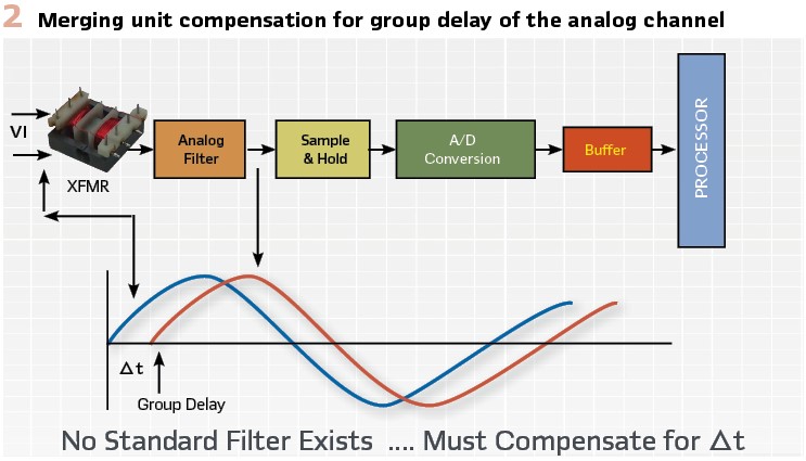
When SV data comes from a “Synchronized” Merging Unit, they will at least be locally synchronized and, if GPS is functioning in the station, would be Globally Synchronized. Additionally, the time stamps on the data must compensate for any Phase Angle shift resulting from the measurement system (see Figure 2). When the data is compensated, the samples can be marked as “Synchro Samples” and can then be aligned via the time stamp alone. The feature is extremely useful when looking to integrate and view data from multiple substations on a single screen.
In 61850, STATUS values (e.g. – Sequence of Events) also contain a Quality attribute. Specifically, errors in the recording of such can be mapped into Quality and whether or not the value is Measured or Substituted is captured. It has been proposed that Binary Status Quality attribute be included in the STATUS values in a COMTRADE file.
61850 does define a Data Recorder model through which names of channels and devices can be included. In IEC 61850 based systems the information exchange for sampled values is based on a publisher/subscriber mechanism.
The currents and voltages from TCTR and TVTR accordingly are delivered as sampled values over the substation LAN using one of the communication modes described earlier in the article (see Figure 3).
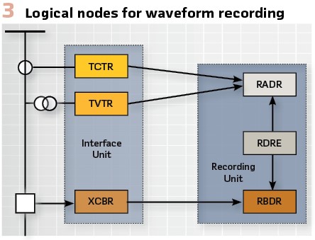
The status of the breakers in the substation is modeled using the XCBR logical node. It will provide information on the three phases or single-phase status of the switching device, as well as the normally open or closed auxiliary contacts. Figure 3 shows a simplified block diagram of the logical nodes used to model the different components of the waveform recording function.
As can be seen from the figure the TCTR, TVTR and XCBR logical nodes are implemented in the different interface units. This name is used instead of merging units due to the fact that the devices have binary inputs in addition to the analog inputs typically available in merging units.
RDRE is the logical node representing the acquisition functions for voltage and current waveforms from the power process (CTs, VTs), and for position indications of binary inputs. RDRE is used also to define the trigger mode, pre-fault, post-fault etc. attributes of the disturbance recording function.
RBDR is used for the different binary signals used in the recording device and RADR logical nodes represent multiple analog channels recorded.
These names are embedded in the device Configuration file (CID) and it is proposed that the XML COMTRADE investigate the automatic migration of this data into the XML COMTRADE configuration file. To be included in the mapping would be the 61850 “fully qualified” device name. In general, only the first data item in the Configuration would need the fully qualified name and the other data items would “inherit” the source name.
However, when files are merged, the Fully Qualified name for the new source of data must be included in the data name.
A 61850 device can contain the Latitude, Longitude, and Altitude of the source device / GPS clock. Applications such as Frequency Network (F-NET) that capture frequency at different locations would benefit from being able to share this information in COMTRADE files. It is recognized that posting such information in a COMTRADE file may pose a security threat. It will ultimately be up to the Standard WG to address this issue.
In as much as the configuration language for IEC 61850 is based on XML, it now makes sense to have an XML-based version of COMTRADE. The XML version would meet strict XML formation rules – including the DATA area where it is proposed that the mapping of the DATA file be done through what is known as Base64 Encoding.
In Base64 encoding, a set of 64 printable characters are used to convey 6 bits of the Binary DATA file. For example, to store 3 binary bytes of data (24 bits) would require 4 Base64 characters (32 bits) – essentially a 33% overhead. It should be noted, however, that with the entire file being XML compliant, ANY web browser could be used to open the file. The design of the XML-COMTRADE would be such that a program could be used to convert from the XML format to the standard COMTRADE format.
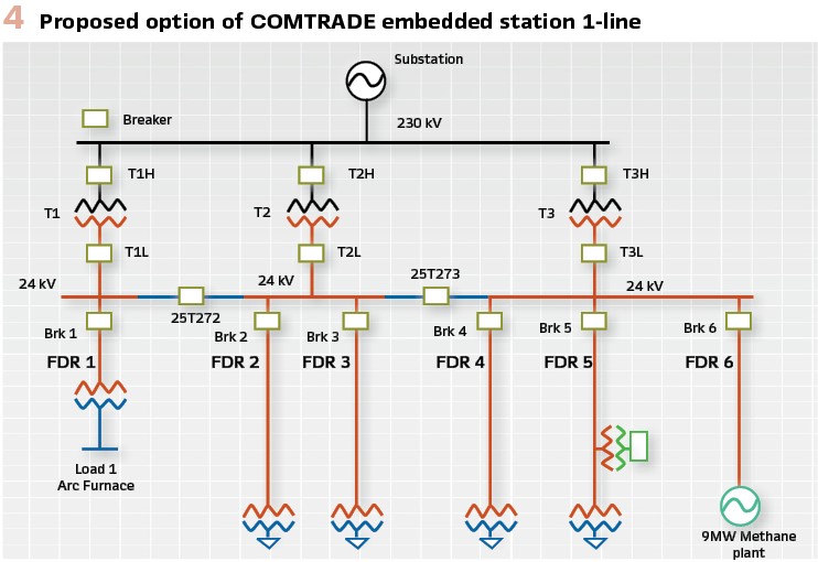
With the XML file able to be opened in a Web Browser, it is proposed that the XML version of COMTRADE be able to contain Web Pages (Figure 4). The web pages could contain the state of the substation or adjacent system both before and after an event. Measurements of voltages. current, and fault currents could be included on the page.
As COMTRADE has become a Dual Logo standard (IEEE and IEC), it becomes desirable to “internationalize” all user-defined names in COMTRADE.
To accomplish this, it has been proposed that the User Defined Name Fields should be based on Unicode Characters (UTF8). Unicode represents characters and symbols by a number. As of March 2020, there were 143,859 symbols defined in Unicode.
Virtual Channels
In the analysis of an event, it may be desirable to view information that is not directly contained in the base COMTRADE data but can be derived from the available data.
The concept of Virtual Channels is proposed for the next version of COMTRADE. An example of a virtual channel would be where the engineer has 3-phase currents but would like to see the associated Ground current. It is well known that the ground current is equal the sum of the phase currents.
To facilitate implementation of a computational language, it is proposed that the Virtual Channel formulas be based on Excel formulas – including access to functions such as Sine, Cosine, exponentiation, etc. As such, a virtual channel would be created as:
Line ABC Ground Current;
=ABC_Ia + ABC_Ib + ABC_Ic; persistent or temporary
Most Optical CTs do not measure ground current so it must be computed. Whether or not it is included in the COMTRADE record is typically user selectable.
The end category – persistent or temporary – would be a characteristic whereby if persistent, once computed, the Virtual channel could become part of the permanent file. Clearly, a “Temporary” channel is computed each time the file is opened in a COMTRADE tool. Note that the Virtual Channel option would be available in both Basic and XML COMTRADE.
Through the use of advanced functions, virtual channels could be used to compute Power Factor which would look like:
Line_ABC Power Factor: =cos(atan(Imaginary Power/Real Power))
Through the use of more advanced formula structured, functions such as the computation of RMS and Phasor values could be achieved.
Additional Proposed Updates
In most circumstances, a COMTRADE file is generated as a result of a fault or an action by a relay. Today’s digital relays can have setting files remotely downloaded and most relays have multiple groups of settings that can be remotely activated. In order to facilitate analysis of “what happened,” it is proposed that the Name of the Active Setting file be included in the COMTRADE record. Additionally, the Number of the Active Setting Group when the COMTRADE file was triggered should also be included.
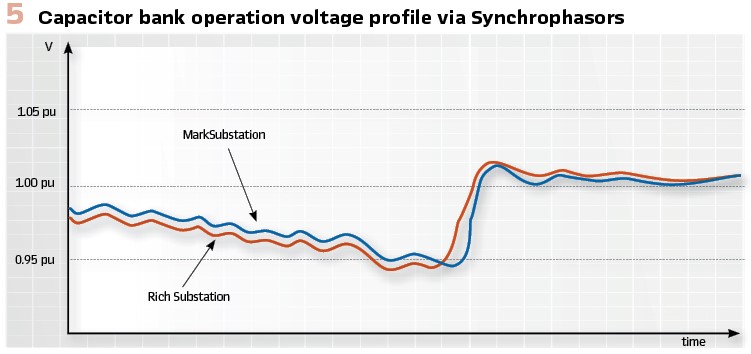
The wide-spread use of Synchrophasors to view data (see Figure 5) required a mechanism to save them in a file format. In as much as Synchrophasors are Time Sequenced data, COMTRADE was a logical file format into which Synchrophasors could be mapped. A schema for performing this mapping was developed by an IEEE Power System Relay Committee that defined how Synchrophasors – which are Complex numbers – are to be mapped into COMTRADE.
It is proposed that this schema be formally adopted as part of the Synchrophasor standard. Specifically, it is proposed that a Complex Data Type be defined in COMTRADE.
It should be noted that the IEEE PSRCC report that defines this mapping in available through the PSRCC Web Site.
Integrated Data Recording
Similar in nature to Synchrophasors, it would be desirable to be able to map Harmonic and RMS data into COMTRADE. Both of these data types require the integration of multiple samples of data over one or more cycles. While both these data types can be included in a COMTRADE file today, the present file structure requires that they be repeated each sample. As such, for a device with a sample rate of 64 samples per nominal cycle, 63 of the 64 RMS or Harmonic values included in the record are repeated. It is proposed to create a Periodic Value inclusion function in COMTRADE wherein where the channel definition includes the repeat rate of the integrated value. In the example above where the sample rate is 64 samples per cycle, a repeat rate of 64 samples would be specified in the channel definition.
If the sampling device performs frequency tracking, the sample rate and the report rate will operate in Lock Step. With Process Bus data, however, this will not be the case as the samples always have the exact same ∆t. As such, the integration function may have a ±1 sample variance as to when an RMS or Harmonic value is emitted.
A mechanism is therefore needed to alert the reading software that a particular sample contains “extended” data values. One mechanism proposed is to set the Most Significant bit of the Sample Count to a “1” to indicate such.
Dealing with Sparse Digital Data
COMTRADE defines the mapping of Digital Data through the use of a 16 bit Unsigned Integers that are reported at the same rate as the analog sample data. Since most Digital Relays do not sample the Status Inputs at the same rate as the Analog Values, many if not most, of the Digital Sample Values (as well as the proposed Status Value Quality flags) are repeated with identical data (see figures 6a).
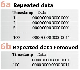
The repeat of identical data has been addressed in many Historians through the use of sparse data techniques. In these techniques, repeated data is identified and removed. Only when a “change” in the data is detected is the updated data reported – with the appropriate timestamp (see Figure 6b).
Finally, the IEEE PSRCC has developed a “standard” File Naming convention: C37.232-2011 – IEEE Standard for Common Format for Naming Time Sequence Data Files (COMNAME) – for the “standardized” naming of Time Sequence files – to which COMTRADE identifies.
The Naming Convention contains information about:
- Start Date
- Start Time
- Time Code (offset from UTC)
- Station Name
- Device Name
- Company Name
- User-defined fields
It is proposed that the use of the IEEE C37.232 standard be mandated by the next generation COMTRADE.
COMTRADE is the industry standard for the storage of Fault Information and Synchrophasors as well as for the playback of test files for relay performance evaluation. With the proposed Next Generation upgrade for COMTRADE, it is clear that it will leave its mark on the industry for many years to come.
Biography:
Mark Adamiak is an independent consultant for the electric power industry. Mark started his career in the utility business with American Electric Power (AEP) and in mid-career, joined General Electric where his activities have ranged from advanced development, product planning, application engineering, and system integration in the Protection and Control industry. Mr. Adamiak is an original member of the IEC61850 WG, a Life Fellow of the IEEE, a registered Professional Engineer in the State of Ohio and a GE Edison award winner. Mark was the Principal Investigator for the EPRI IntelliGrid project to develop a reference architecture for the Smart Grid. In 2012, Mr. Adamiak was elected to the US National Academy of Engineering