by Alexander Apostolov. USA
Protection, automation and control applications are some of the key components in the reliable and secure operation of the evolving grids of the twenty first century. The complexity of today’s electric power grid and its changing dynamic characteristics together with the rapid development of computer and communication technologies resulted in the transition from the conventional hard-wired protection, automation and control systems to IEC 61850 based solutions in digital substations.
Time plays an important role in everything in our lives. It is used to establish when an event will occur and what its duration will be, to measure the duration of events and the time interval between them, to synchronize multiple devices so they can work together as components of a system and many others.
That is why the development of the IEC 61850 standard had to consider the requirements for time in the data and object models, as well as in the communications services’ definitions.
At the same time, the standard must adapt to the developments in time synchronization technology and how it can be implemented in the different protection, automation and control systems.
Time Related Requirements
Time synchronization has been a requirement for electric power systems protection, automation and control systems (PACS) since the introduction of microprocessor based multifunctional PAC and recording devices.
The need was to be able to analyze the operation of multiple devices at different physical locations in response to an electric power system event. This was further extended based on the need to measure electric power system parameters in different physical locations.
The IEC 61850 standard uses the PICOM (Piece of Information for Communication) concept developed by CIGRE Working group 34.03 and published in Technical Brochure B5 180 “Communication requirements in terms of data flow within substations.” It is focused by definition on the exchanged data between two application functions or subfunctions within a substation. One of the components of the PICOM is the Time tag defined as an absolute time to identify the age of the data if applicable.
IEC 61850 defines different requirements for the development of the standard that include also time related requirement as follows:
- Accuracy – depending on the application, different time accuracy is required
- The time stamp shall be based on an existing time standard (UTC is generally accepted as the base time standard)
- The time model shall be able to track leap seconds and provide enough information to allow the user to perform delta time calculation for events crossing the leap second boundary
- The time stamp model shall contain sufficient information that would allow the client to compute a date and time without additional information such as the number of leap seconds from the beginning of time
- The timestamp shall be easily derived from commercially available time sources
- The overall time model shall include information to allow computation of local time
- The time model shall allow for ½ hour offsets for Local Time
- The time model shall indicate whether Daylight Savings is in effect or not
- The format shall last at least 100 years
- The timestamp format shall be compact and easily machine manipulated
Event Time Definition: The industry has been looking at the topic of time stamping for many years in an effort to standardize the definitions based on a common understanding of the types of time-stamps required. IEC 61850-5 defines three different kinds of events, which need a dedicated time allocation procedure:
- If an event is defined as the result of computation (internal or calculated event) allocation of time (time tagging) shall be done immediately within the time resolution of the clock. No special measures are needed
- If an event is defined as change of a binary input the delay of the debouncing procedure of the input contact must be considered. The event time shall be locally corrected
- If an event is defined as change of an analogue input the delay of the filtering procedure of the input circuit has to be considered. The event time shall be locally corrected
This strong event time definition ensures that the processing of the time stamp becomes independent from the communications system latency and does not require correction by the receiving function.
Table 1 shows the time performance classes for almost all events related applications and depend on the supported functionality.
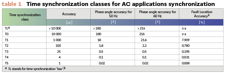
With the introduction of synchrophasor measurements the need for much more precise time synchronization arose. This is due to the fact that a 1 ms accuracy (T1 class in Table1) results in a phase angle measurement error of 18 deg in a system with a nominal frequency of 50 Hz. To reduce this error, the time-synchronization has to be in microseconds range with different performance classes being defined in IEC 61850. T3 accuracy will be OK for most applications, but it is commonly accepted that PMUs need to be synchronized to meet T5, i.e. with an accuracy of 1 µs.
With the introduction of optical current and voltage sensors or stand-alone merging units used for process interface in digital substations, a similar requirement was established for their time synchronization.
Time in the IEC 61850 Model
As described in the previous section, IEC 61850 introduces requirements for time-tagging of events for use in different protection, automation and control applications. This requires also the definition of time related data objects and attributes in the IEC 61850 model.
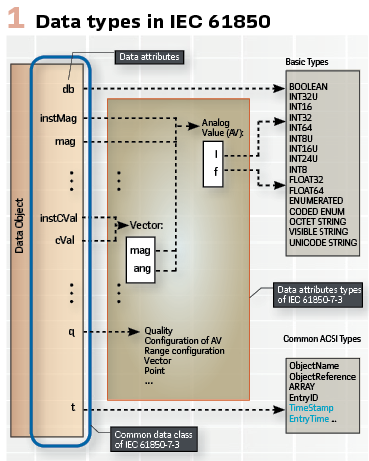
Figure 1 shows the different data attributes and data types used in the standard data model defined in IEC 61850-7-3.
One of the common attributes of data objects is t, representing a time stamp or an entry time related to a change of the value of the data object.
The TimeStamp type shall represent a UTC time with the epoch of midnight (00:00:00) of 1970-01-01 specified.
Another time related attribute in the model is FractionOfSecond representing the fraction of the current second when the value of the TimeStamp has been determined.
The TimeQuality is an attribute in the object models that provides information about the time source of the sending device and includes information about:
- LeapSecondsKnown
- ClockFailure
- ClockNotSynchronized
- TimeAccuracy
The above information is used by the receiving device to properly process the data in the message.
Time Settings for Protection Functions
Many protection functions do not operate instantaneously after the parameter they monitor exceeds the setting threshold. They are delayed by a time setting or a time characteristic.
A simple example is the time delay of the operation of a distance element in a transmission line protection represented by the logical node PDIS.
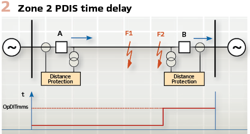
It is represented by the data object OpDlTmms and is defined in the IEC 61850 standard as “Time delay before operating once operate conditions have been met.” (Figure 2).
The time delay setting is of the CDC ING (Common Data Class Integer status setting). The attributes of ING are:
- setVal – value of the setting
- minVal – Minimum setting for ‘setVal’
- maxVal – Maximum setting for ‘setVal’
- stepSize – the step size of the setting
- units – the units of the setting
In the case of the time delay setting OpDlTmms it is in milliseconds.
Time in the GOOSE Model
High-speed peer-to-peer communications in IEC 61850 based protection and control systems use a specific method designed to meet a variety of requirements. The GSE method can be considered as a mechanism for unsolicited reporting by a logical device. The achievement of speed performance, availability and reliability depends on the implementation in any specific device.
The generic substation event model is used to exchange the values of a collection of Data Attributes defined as a Data Set. Edition 2 of the standard defines GOOSE – Generic Object Oriented System Event that supports the exchange of a wide range data types organized in a data set.
The GSE information exchange is based on a publisher/subscriber mechanism. The publisher writes the values in a transmission buffer at the sending side and multicasts them over the substation local area network to the different subscribers.
The data in the published GOOSE messages is a collection of values of data attributes defined as members of a data set. The receiver reads the values from a local buffer at the receiving side. A GSE control class in the publisher is used to control the process. If the value of at least one of the DataAttributes has changed, the transmission buffer of the Publisher is updated with the local service “publish” and the values are transmitted with a GOOSE message.
The publisher/subscriber mechanism allows the source IED to reach multiple receiving IEDs thus significantly improving the efficiency of the communications interface. The time when a message will be received by the subscribers may vary depending on the latency affected by the communications architecture and the traffic on the network.
Since the GOOSE messages replace hard-wired signals used for protection and control applications, IEC 61850 introduces mechanisms that ensure the delivery of the required information. Once a new value of a date attributed has resulted in the multicasting of a new GOOSE message, the repetition mechanism ensures that the message is sent with a changing time interval between the repeated messages until a new change event occurs.
One of the data objects in a GOOSE message is StNum – state number. It represents the value of a counter that increments each time a GOOSE message has been sent and a value change has been detected within the GOOSE data-set.
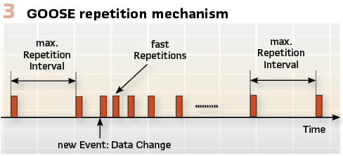
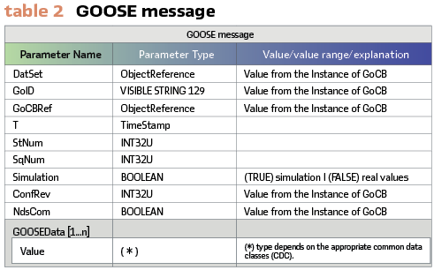
The initial value for StNum upon a transition of GOOSE Enable (GoEna) to TRUE is 1. (Figure 3). Any change of value in the GOOSE data set will also result in a new value of the parameter T (TimeStamp) in the GOOSE message. (Table 2).
As shown in Figure 3, at the beginning after a change (newEvent) the parameter SqNum (Table 2) is set to a value of 0. It is a counter that shall increment each time a repeated GOOSE message has been sent, while StNum maintains the same value.
Following a change, the repetition interval is very short – a few milliseconds, which later increases until it reaches a value of a few seconds. This method achieves several important tasks:
- Ensures that a loss of a single message is not going to affect the functionality of the system
- Allows any new device to inform all subscribing devices about its state
- Allows any new device to learn the state of all publishing devices it subscribes to
The GOOSE messages (Figure 3) contained information allows the receiving devices to know not only that a status has changed, but also the time of the last status change. Based on this a receiving device can set local timers relating to a given event.
Time in Sampled Values Communications
IEC 61850 uses merging units based on IEC 61850-9-2 (Process Bus) for the analog interface in digital substations. Existing Merging Units have the following functionality:
- Signal processing of all sensors – conventional or non-conventional
- Synchronization of all measurements – 4 currents and 4 voltages
- Analog interface – high and low level signals
- Digital interface – IEC 61850-9-2
It is important to be able to interface with both conventional and non-conventional sensors in order to allow the implementation of the system in existing or new substations.
Interoperability between merging units and protection, control, monitoring or recording devices is ensured through a document providing implementation guidelines. Two modes of sending sampled values between a merging unit and a device that uses the data are defined. For protection applications the merging units send 80 samples/cycle in 80 messages/cycle, i.e each Ethernet frame has the MAC Client Data contain a single set of V and I samples. For waveform recording applications such sampling rate may not be sufficient. That is why 256 samples/cycle can be sent in groups of 8 sets of samples per Ethernet frame sent 32 times/cycle.
The sampled analog values model applies to the exchange of values of a DATA-SET. The difference in this case is that the data of the data set are of the common data class SAV (sampled analogue value as defined in part IEC 61850-7-3). A buffer structure is defined for the transmission of the sampled values that are the output from the instrument transformer logical nodes TCTR and TVTR.
The information exchange for sampled values is based on a publisher/subscriber mechanism.
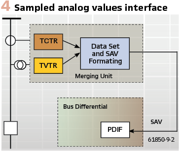
The publisher writes the values in a local buffer at the sending side, while the subscriber reads the values from a local buffer at the receiving side. A time stamp is added to the values, so that the subscriber can check the timeliness of the values and use them to align the samples for further processing. The communication system is responsible for updating of the local buffers of the subscribers. A sampled value control (SVC) in the publisher is used to control the communication procedure. (Figure 4).
The currents and voltages from TCTR and TVTR accordingly are delivered as sampled values over the substation LAN.
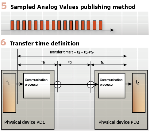
In this case the network becomes the data bus that provides the interface between the instrument transformer logical nodes and the different logical nodes that are used to model the functional elements of the IED. (Figure 5).
The publishing of the sampled values is based on a fixed time interval between the individual samples without a repetition mechanism. Under the IEC 61850 9-2 LE implementation agreement the publishing rate is 80 samples (messages)/cycle at the nominal frequency.
The key time related data in the SV message is the parameter SmpCnt. It contains the values of a counter, which is incremented each time a new sample of the analogue value is taken. The counter values can be converted by the subscriber into a time stamp value within the current second. Since the counter is typically used to indicate time consistency of various sampled values within a second, the counter is reset to zero by an external synchronization event. The first IEC 61850 based merging units were synchronized using 1 pps signals. Today the time synchronization is performed using IEC 61850-9-3.
Sample count needs to be converted to sample time to be used for transient and disturbance recording.
Transfer Time
IEC 61850 defines the complete transfer time as shown in Figure 6. This means the complete transmission of a message includes necessary handling at both ends. The time counts from the moment the sender puts the data content on top of its transmission stack up to the moment the receiver extracts the data from its transmission stack.
The time requirement is applicable for the complete transmission chain as indicated in Figure 6. In physical device PD1, a function f1 sends data to another function f2, located in physical device PD2. The overall transfer time will however consist of the individual times of the communication processors and the network transfer time, including wait times and time used by routers and other devices being part of the complete network. The difference between the time stamps of the changed value in the publisher and in the subscriber can be used to calculate the transfer time between time synchronized devices.
Time Protocols
Edition 1 of IEC 61850 defined SNTP ((Simple Network Time Protocol) as the protocol for time synchronization. It provides sufficient accuracy (1 ms) for time-tagging of events, but cannot be used for synchronizing of merging units and PMUs that require time synchronization accuracy of 1 microsecond. That is why in Edition 1 based systems the accurate time synchronization is based on 1 pps signals.
The introduction of 1588-2002 – IEEE Standard for a Precision Clock Synchronization Protocol for Networked Measurement and Control Systems provided a much better solution for accurate time synchronization in digital substations. It is known as Precision Time Protocol (PTP) and is applicable to systems communicating by local area networks supporting multicast messaging including but not limited to Ethernet. It enables heterogeneous systems that include clocks of various inherent precision, resolution, and stability to synchronize to a grandmaster clock and supports system-wide synchronization accuracy in the sub-microsecond range with minimal network and local clock computing resources.
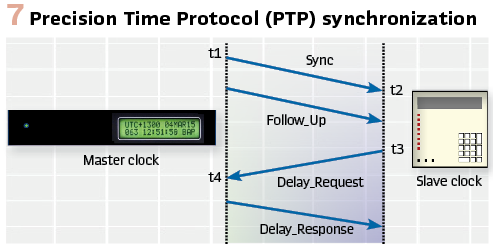
IEEE 1588 V2 was published in 2008 to improve the accuracy, precision and robustness, however it is not backward compatible with the 2002 standard. (Figure 7).
Considering the many options available in IEEE 1588 V2 in order to adapt it for the needs of power system applications, IEEE and IEC developed profiles of the standard. The IEEE PSRC initially released IEEE C37.238-2011 – the original power profile for PTP. It defined clock accuracy requirements; additional type, length, and value structures; and settings limits. In 2016, IEC TC 57 Working group 10 released their version of the power profile (IEC/IEEE 61850-9-3 Edition 1). This version adjusted the profile to include specific requirements deemed critical for use in power system timing by IEC.
IEEE updated the C37.238 standard (C37.238-2017) to align with the IEC standard and provide additional requirements. The most significant change was splitting this standard into two standards: the new joint standard International Electrotechnical Commission (IEC)/IEEE 61850-9-3 and the now revised IEEE C37.238-2017. The reason for the change was that the two main sponsoring organizations IEC Technical Committee (TC) 57 Working Group (WG) 10 and IEEE Power and Energy Society (PES) Power Systems Relay Committee (PSRC) expressed significant differences in their expectations from this work. The result was that IEC/IEEE 61850-9-3 became the technical specification document, providing the baseline performance level required for all applications.
Additional requirements supported by the revised IEEE C37.238 include real-time updates of the delivered time quality (inaccuracy), plus inclusion of the data needed to support the migration of substation time-distribution networks from IRIG-B.
Time Synchronization Sources

Time synchronization of the devices in the substation is based on a dedicated time server which receives the time signal from a single or multiple GNSS (space-based global navigation satellite system): GPS, GLONASS, Galileo, BeiDou satellites. GNSS provides reliable positioning, navigation, and timing services to users on a continuous worldwide basis freely available to all. (Figure 8).
The Global Positioning System (GPS) is a U.S.-owned utility that provides users with positioning, navigation, and timing (PNT) services. This system consists of three segments: the space segment, the control segment, and the user segment. The U.S. Air Force develops, maintains, and operates the space and control segments. The GPS space segment consists of a constellation of satellites transmitting radio signals to users. The United States is committed to maintaining the availability of at least 24 operational GPS satellites, 95% of the time.
Galileo is the European system that also requires 24 satellites to operate and provides better accuracy than GPS (20 cm for the encrypted version and 1 m for the regular, compared to the 3 m for the regular GPS).
GLONASS is the Russian system that needs 24 satellites as well and has comparable accuracy to GPS.
The Chinese GNSS is called BeiDou Navigation Satellite System (BDS) and its first version was also known as Compass (providing limited coverage). The 3rd generation of BeiDou is expected to be completed this year and is expected to provide sub-centimeter accuracy.
Considering the criticality of the accurate time synchronization and the cyber security concerns, some advanced substation clocks combine GNNS signals with a built-in atomic clock.
Conclusions
Time is a critical component of any protection, automation and control function in digital substations and many power grid applications. That is why IEC 61850 has made significant efforts to ensure that time is covered in sufficient detail by the object models in the standard, as well as the communications services used by different interfaces and applications.
Time accuracy and quality are defined from the point of view of the requirements of different use cases and applications.
Different time sources and the use of PTP ensure that all the data used within the system will maintain continuously high-accuracy time synchronization to improve the reliability and security of the electric power grid.
Biography
Dr. Alexander Apostolov received his MS degree in Electrical Engineering, MS in Applied Mathematics and Ph.D. from the Technical University in Sofia, Bulgaria. He is Principal Engineer for OMICRON electronics in Los Angeles, CA. He is an IEEE Fellow and Member of the PSRC and PSCC. He is past Chairman of the Relay Communications Subcommittee, serves on many IEEE PES WGs. He is a member of IEC TC57 WGs 10, 17, 18, 19, Convenor of CIGRE WG B5.69 and member of several other CIGRE B5 WGs. He is a Distinguished Member of CIGRE. He holds 4 patents and has authored and presented more than 500 technical papers. He is an IEEE Distinguished Lecturer and Adjunct Professor at the Department of Electrical Engineering, Cape Peninsula University of Technology, Cape Town, S. Africa. He is Editor-in-Chief of PAC World Magazine.