Digital Instrument Transformers and Digital Switchgear Interface
by Stelian Parushev, Siemens Energy, Germany
Over the years, the evolution of protection, automation, and control (PAC) systems has brought significant transformations of the high voltage substations. The transition from pure electromechanical systems to solid state relays with simple electronic components, and ultimately to the advanced numerical protection automation and control systems in use today, has revolutionized the way substations are managed and operated. While these advancements have predominantly impacted the bay and station levels, the same level of innovation has not been as prevalent at the process level.
In a high voltage substation, the process interface functions are grouped in three categories: Electrical Interface, Non-Electrical Interface and Switchgear Interface. We can realize these functions by grouping logical nodes within logical devices. When it comes to naming the logical devices, we use the following conventions. Switchgear interface unit (SIU) provides a binary status and control interface for circuit breakers and switches. Merging unit (MU) converts currents and voltages into time-synchronized streams of sampled values according to IEC 61850-9-2 or IEC 61869. Nonelectric interface unit (NEIU) converts analog signals from nonelectric sensors into time-synchronized streams of sampled values according to IEC 61850 9-2 or GOOSE messages according to IEC 61850-8-1. (Apostolov, 2023) The decision of which of these logical devices to implement in the physical IEDs is left to the manufacturer.
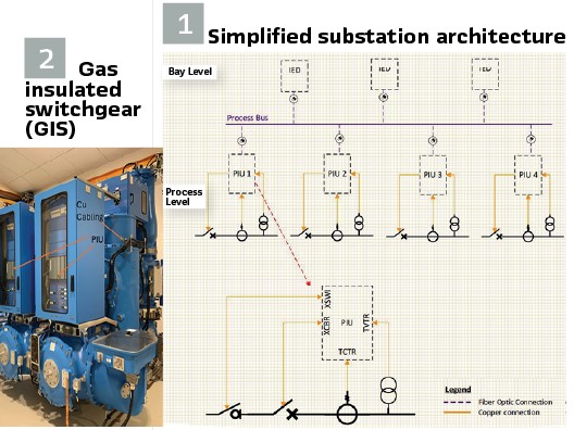
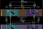
In the first example shown on Figure1, let’s examine the process level of a typical simplified substation architecture. This architectural configuration, often designed by system integrators, features an Intelligent Electronic Device (IED) that combines all logical devices in one IED called Process Interface Unit or (PIU).
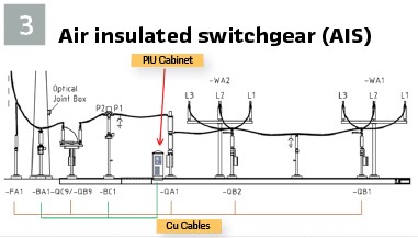
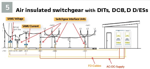
A significant advantage of utilizing Process Interface Units (PIUs) in high voltage substations is the capability for Data Concentration. PIUs can collect and concentrate data from multiple points within the substation before sending it to the central Protection, Automation, and Control (PAC) system in a GOOSE or SMV format. This function significantly reduces the amount of communication traffic and enhances bandwidth utilization, leading to a more efficient and streamlined data management process. On the market, there are compatible Process Interface Units (PIUs) both for Low Power Instrument Transformers (LPITs) and conventional instrument transformers. When it comes to the question of copper cable reduction and digitization of current and voltage as close as possible to the source, the maximum that can be achieved with these types of process interface units is when they are installed directly in the local control cabinet mounted on Gas Insulated Switchgears (GIS) next to the process. This configuration, as shown in Figure 2, still requires copper cables from the instrument transformers and switches. However, in the case of Air Insulated Switchgear (AIS) Figure 3, one of the advantages, namely data concentration, becomes a disadvantage. This is due to the fact that the process interface unit needs to be placed in an outdoor cabinet in the switchyard, somewhere between the instrument transformers and switches, or if placed next to one device the distances increase from another. Consequently, this requires even longer copper cables compared to Gas Insulated Switchgear (GIS).
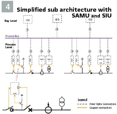
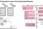
If the goal is to reduce the use of copper cables and digitize signals via PIUs, a single PIU must be placed next to each equipment (CT, VT, CBs, etc.), however, this is not financially feasible. Clearly, there is a need for a cost-effective solution that does not increase system complexity. One potential solution is the utilization of stand-alone merging units (SAMUs) for separate current and voltage measurements, along with a switchgear interface unit (SIU) for binary signals from disconnectors and circuit breakers. According to IEC 61869-13:2021 SAMU Stand- alone merging unit has a standardized analogue input (for example: 1 A, 5 A, 3,25 V / √3 or 100 V / √3) provided by instrument transformers and convert them to the digital output compliant with IEC 61869-9. Figure 4 illustrates a simple architecture that includes a SAMU for current, a SAMU for voltage, and a switchgear interface unit. This configuration gives the idea that these data acquisition devices can be installed in close proximity to the process. Furthermore, most SAMUs available on the market have compact dimensions, allowing for integration directly within the instrument transformers. Following the example of the SAMU, the SIU can be segregated into a Circuit Breaker Interface unit and a Disconnector/Earthing Switch unit or simply scalable remote IO unit. This approach obviously provides the convenience of the Instrument Transformer and switching equipment manufacturers to directly include the SAMUs and IO units in the corresponding products during manufacturing, pre-test them and provide to the end customer products with IEC 61850 / IEC 61869 compatible interface using only fiber optic (FO) cables instead of copper cables for connection with the process buss communication switches. This products with other words can be called digital instrument transformer, digital circuit breakers and switches. If we try to give definitions, a Digital Instrument Transformer (DIT) is an advanced device that integrates the functions of traditional instrument transformers with digital technology, including the capabilities of a Standalone Merging Unit (SAMU). This device is designed to accurately measure high voltage and current levels in power systems and convert these measurements into standardized digital outputs, which can be easily used for metering, protection, and automation purposes in a digital substation environment. The Digital Instrument Transformer comprises the following:
1. Sensing Element: The DIT contains a sensing element, which could be a conventional wound-type transformer or a non-conventional sensor-based technology (such as optical or Rogowski coils) to detect the primary high voltage or current
2. Analog-to-Digital Conversion (ADC): The analog electrical signals from the sensing element are converted into digital data through high-resolution ADCs. This process involves precise sampling of the analog signals at predetermined intervals
3. Digital Signal Processing (DSP): The digitized data is then processed using DSP techniques to enhance signal quality and to extract the required measurement parameters such as magnitude and phase of the voltage or current
4. Data Formatting and Merging: Following DSP, the digital data is formatted according to IEC 61850-9-2 Sampled Values (SV) protocol or other relevant standards such as IEC 61869-9. The DIT functions similarly to a SAMU by merging these data streams into a unified output that can be transmitted to the digital substation’s communication network
5. Time Synchronization: The DIT incorporates precise time-stamping of the digital measurements using protocols like IEEE 1588 PTP, ensuring synchronization across all devices within the substation
6. Communication Interface: The DIT uses an Ethernet-based interface to communicate the time-synchronized, digital sampled values to the substation’s control and protection systems. It supports multicast messaging, allowing multiple devices to access the data simultaneously.
The Digital Instrument Transformers provide several benefits over traditional instrument transformers, including improved accuracy, enhanced safety due to galvanic isolation, reduced size and weight, and the elimination of secondary wiring. Additionally, by directly outputting digital data, DITs facilitate easier integration with Intelligent Electronic Devices (IEDs) and contribute to the modernization of power systems through the implementation of smart grid technologies.

A Digital Circuit Breaker is an advanced electrical device that combines the traditional functionalities of a high voltage circuit breaker with the capabilities of a Switchgear Interface Unit (SIU) or Remote Interface Unit (RIU) to provide comprehensive digital control, communication, and monitoring features.
This integration results in a circuit breaker that not only interrupts and isolates electrical currents during fault conditions but also seamlessly interfaces with digital substation automation systems.
The Digital Circuit Breaker includes the following key components and features:
1. Interrupting Mechanism: It retains the core mechanical elements of a conventional high voltage circuit breaker, capable of opening and closing electrical contacts to interrupt the current flow in the event of overcurrent or short circuit conditions.
2. Intelligent Electronic Module: This module digitizes binary status signals from the mechanical parts of the circuit breaker (such as position indicators and alarm contacts), enabling the status of the breaker to be monitored in real-time by the substation control system. Also interact with the tripping coils providing the tripping possibilities of the protections systems.
3. Communication Capabilities: The intelligent module uses IEC 61850 GOOSE messaging for fast and reliable communication with other Intelligent Electronic Devices (IEDs) in the substation network. It can send status updates, receive control commands, and participate in automated protection and control schemes
4. Local Control Logic: The Digital Circuit Breaker may include embedded control logic that can process inputs and execute commands based on predefined conditions or interlocking schemes, ensuring safe and proper operation
5. Local protection functions: If the Digital Circuit breaker is equipped with integrated LPIT or conventional combined instrument transformer e.g. Dead Tank CBs, some local protection functions can be realized as back up functions in case of communication interruptions of process/station bus or other problems such as power outages or separation of the process with the other levels of the digital substation
6. Time Synchronization: To facilitate accurate timing for protection and control operations, the Digital Circuit Breaker supports precise time synchronization protocols like IEEE 1588 PTP
7. Remote Operation and Monitoring: With its digital communication interface, typically Ethernet-based, the Digital Circuit Breaker allows for remote operation, monitoring, and diagnostics, enhancing the flexibility and accessibility of power system management
8. Arc Extinguishing: The Digital Circuit Breaker uses advanced technologies (such as vacuum, SF6, or air blast) to extinguish arcs efficiently when interrupting high currents, ensuring reliability and safety
By integrating the mechanical and digital functionalities, a Digital Circuit Breaker provides a more intelligent, reliable, and efficient solution for power system protection. It supports the modernization of the grid by enabling the implementation of smart grid technologies and interoperability within a digital substation environment.
A Digital Disconnector and Earthing Switch are equipped with a Remote I/O Unit (RIU) that enables remote control and status monitoring, allowing for the operation and confirmation of the switch positions via digital communication within a smart grid infrastructure.
Figure 5 suggests how an Air Insulated Switchgear (AIS) switchyard would look utilizing digital instrument transformers, digital circuit breakers, and digital disconnector/earthing switches. In this configuration, it is clearly visible that the copper cable wiring in the switchyard is significantly reduced, essentially brought down to just the power supply for the digital equipment.
The transition to fiber optics enhances reliability and significantly reduces electromagnetic interference, which is critical in maintaining accurate measurements and control signals in high voltage environments.
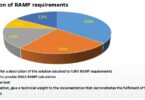
Moreover, the adoption of the solution within substations simplifies the overall infrastructure by minimizing the physical and environmental footprint and the extensive cabling requirements traditionally associated with analog systems. This not only cuts down on installation and maintenance costs but also improves the scalability and flexibility of substation design. In addition, there are several technical problems which are solved born with the installation of digital Instrument Transformers and digital switches:
Unnecessary high secondary burden in the analogue measurement loops for current (Current Transformers – PAC) of a High Voltage Substation, due to the high resistance of the copper conductors, which leads to a bigger size of the core of the current transformers. A larger core size of a CT leads to a slower response time due to its increased inductance. This can affect the performance of protection devices that rely on the CT for fast and accurate measurements. A larger core will result in a physically larger and heavier CT, which may not always be desirable, especially in space-constrained applications.
Bigger cores require more magnetic material, which increases the cost of the CT. This was solved up to now partially, by positioning equipment in cubicles in HV yard, which requires additional infrastructure and adds additional cost to the system as the article described above.
The burden of the CT core is based on the length of the cable that is between the CT and the relay and the consumption of the relay. In the past the relays needed higher VA to work properly, but nowadays with the relays in the market this burden is normally lower than 0.5 VA, making the cable big part of the burden. This burden is based on the current we have and the resistance of the cable with the formula P = I2 x R (Figure 6, Figure 7).
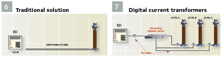
A study conducted in 2024 in Germany shows that if we made a comparison between traditional Current Transformers (CT) and Digital ones for different voltage levels (145 kV, 245 kV, and 550 kV), the following results are observed:
For all voltage levels and a primary current of 600 A, the traditional CT has a secondary current of 5A and requires a burden of 100 VA, costing approximately 100%. The Digital Transformers with a secondary current of 5A and a burden of 2.5 VA have a copper cable length reduction of 98% and cost around 65% at 145 kV, 79% at 245 kV and 87% at 550 kV – a significant price and copper cable length reductions compared to traditional CTs across all voltage levels.
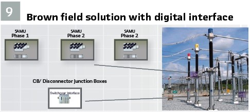
Electromagnetic interference (EMI) HV substations often have high electromagnetic fields, which can induce noise in the copper cables, thus affecting the accuracy of the current and voltage measurements. This was solved up to now by shielded cables or twisted to reduce the impact of EMI. Capacitive and inductive coupling: Capacitive and inductive coupling can occur between adjacent cables, leading to cross-talk and interference in the measurements. The current solution is by increasing the distance between the cables or using shielded cables. Ground loops: If different parts of the measurement system are grounded at different points, ground potential differences can cause unwanted currents to flow in the copper cables, leading to erroneous measurements. Normally now the engineers are using a common grounding point for the entire system. High cost of the cabling system: Solution up to now was not available, positioning Equipment in Cubicles in HV yard requires additional infrastructure and adds additional cost to the system). The solution with SAMU and the Switchgear Interface Units is also suitable for the refurbishment of substations where there is no planned exchange of primary equipment, such as conventional Instrument.
Transformers and switches with new equipment featuring digital outputs-in other words, brownfield projects. Since the digitization modules for current and voltage are designed for 1 and 5 A, 110 V, and the switchgear interface units have an adjustable interrogation voltage, these devices can be installed in a compact junction boxes and mounted on the corresponding equipment, or in existing control cabinets as suggested on Figure 9.
Low power instrument transformers (LPITs) are becoming increasingly popular as the energy industry moves toward digitalization and more intelligent, automated electric grids. They are a critical component in the modernization of electrical infrastructure, offering advantages in terms of performance, cost, and safety. Most manufacturers offer combined current and voltage measurements in one LPIT unit, which operational principle is based on Rogowski coil for analogue current measurements, and capacitive voltage dividing for AC voltage measurements. Rogowski coils are sensitive to magnetic fields generated by the flow of AC current and are described by the following equation:
u(t) = (-ANµ0)/l x di(t)/dt
where A is the area of the loops, N is the number of the turns l is the circumference of the coil, and μ0 is the magnetic constant. It consists of a helical coil of wire with the lead from one end returning through the center of the coil to the other end, so that both terminals are at the same end of the coil, there is no iron core and therefore no saturation.
For measuring of the primary AC voltage, a capacitive voltage divider is used, which working principle is capacitive coupling. The capacitor is formed by an electrode-ring and the primary conductor itself. As a matter of fact, there are two common practices for measuring the secondary voltage, which primarily depends on the operational principle of the corresponding IED. The first approach measures the displacement current trough the described capacitor according to the following equation:
iC(t) = C x du(t)/dt
where C is the capacitance of the partition. The second measures capacitive voltage. Most commonly the described LPITs are integrated in gas insulated switchgears as alternative to the conventional inductive CT and VTs as well as in air insulated switchgear as part of dead tank circuit breakers. Their analog outputs are standardized and described in IEC 61869-10 and 11, for LPCT Usr in RMS is 22,5 mV – 150 mV – 225 mV and for LPVT the Usr in RMS is 3,25/ 3 V, 100/ 3 V. In IEC 61869-11 the user can find the secondary rated burden, which is defined by a resistance of 2 MΩ in parallel with a capacitance of 50 pF. For redundancy proposes normally the LPITs are equipped with two sets of sensors both for current and voltage.
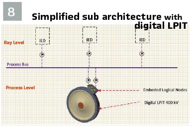
Currently they function with a SAMU or Process Interface Unit (PIU) connected to the analog output, digitizing the voltage and current measurement as per IEC 61850-9-2 or IEC 61869-9. However, there is a need for a special cable, typically limited in length to 5-100 meters, between the LPIT and PIU/SAMU. The cable needs to be shielded to ensure the accuracy of the LPIT remains within defined boundaries. The length of the cable impacts the voltage measurements. The parametrization of the digitization IED is specific because each LPIT unit has unique parameters, such as transformation ratio and the mutual inductance of the Rogowski coil. Some manufacturers provide cloud data bases to make the parametrization convenient, providing information about the corresponding secondary values to the primary current and voltage and from there the transformation ratio can be defined, also information about the channel mapping is required. All this needs to be provided in a special readable file format for the IED and later imported into the corresponding device. This technology requires from the user to learn new ways of parametrization of PIU/SAMU. The digital LPIT however is manufactured unit with embedded Stand-Alone Merging Unit (SAMU) or digitization capabilities providing sampled measured values (SMVs) as per IEC 61850-9-2 or IEC 61869-9 on its outputs, which outputs from the user point of view are communication channels suitable for connecting fiber optic cables allowing the LPIT to provide the SMVs to the process buss network of the substation.

The digital LPIT will avoid the need for a special copper cable and will decrease the vulnerability of the accuracy of the signal due to their capacitive nature. Moreover, the need for a special place in the local control cabinet (LCC) for GIS applications will be eliminated, thus reducing weight and costs. It is also important to be mentioned that the digital LPITs are parametrized and tested by the manufacturer and their performance and particularly quality of digital outputs or SMVs is evaluated during functional performance tests, reducing time and effort for the user during installation and commissioning. (Figure 8).
Beyond the advantages mentioned in the article, the grid of the future will require digital switchyards capable of streaming data not only digitally but also wirelessly. The switches will be autonomous and highly automated, with the capability to clear some faults independently through advanced protection mechanisms.
We are currently at a pivotal moment, laying the foundation for the Instrument Transformers and Switches of the future. Our focus should not only be on digitizing the Protection, Automation, and Control (PAC) system starting from the process level but also on providing flexible and scalable systems that can easily adapt and be updated as technology evolves.
As we move toward this future, it is essential to design systems that can seamlessly integrate with existing infrastructure while offering the ability to upgrade and expand. This adaptability will ensure that our electrical grids remain robust, efficient, and resilient in the face of rapid technological advancements and increasing demand. In essence, we are creating the blueprints for a smarter, more responsive, and interconnected power grid that will meet the needs of tomorrow’s energy landscape.
Biography:

Stelian Parushev received his BS in electrical Engineering in 2014 and a Master of Engineering in Electrical Power Systems in 2016 from the Technical University of Varna, Bulgaria. From 2014 to 2018, he worked for the Electrical System Operator of the Republic of Bulgaria as a substation and relay protection engineer at the Varna 400/220 kV and Dobruja 400/220/110 kV substations ensuring the reliability and safety of the electrical grid, managing substation operations. In 2018, he transitioned to Siemens AG as a commissioning engineer for AC protections in HVDC contributed to 3 major projects: the Pugalur-Kerala 2×1000 MW in India, the Borwin 3 Offshore HVDC in Germany, and the Johan Sverdrup Phase 2 HVDC in Norway. Since 2022, he has been working as a lead engineer for protection systems in high voltage projects and as a key expert in the digitalization of field interfaces and protection systems. He is a member of CIGRE B5 SC Germany and a member of IEC TC 95 WG2 and MT4. His passion lies in the modernization of high voltage substations, driven by a commitment to innovation and technological advancement within the electrical power industry.