by Andre Smit, Quanta Technology, USA, and Camille Ocasio-Rodríguez, LUMA Energy, Puerto Rico
LUMA Energy is taking steps to improve the reliability and resiliency of the distribution systems on the Island of Puerto Rico. The existing distribution system relies on substation circuit breakers and fuses to provide protection.
This old design cannot meet the accepted industry standards for reliability of supply to consumers. Reliability improvement goals necessitate the deployment of communicating reclosers and fault circuit indicators (FCI) on the distribution feeders. The LUMA distribution systems have over 1000 feeders that will ultimately be equipped with reclosers and FCIs.
The project’s scope is to update all the LUMA feeders in 3 to 4 years. LUMA will update eight to ten feeders every week. LUMA Energy teams developed new processes to make the feeder upgrades possible.
LUMA Energy will deploy reclosers as a priority of the distribution automation plan. The FCIs are a second priority for deployment. Concurrently the field devices will be enabled to securely communicate back to the LUMA enterprise for SCADA control and non-operational data.
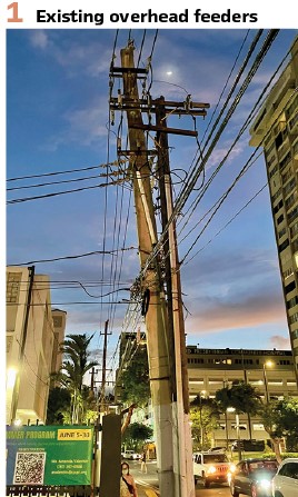
LUMA Energy’s Distribution Automation team must deploy reclosers and fault circuit indicators (FCIs) on the distribution feeders. (see Figure 1).
Distribution Feeder Reliability Improvement
The Island of Puerto Rico has suffered significantly due to the hurricanes. Damage to the distribution feeder system was extensive. Irma as a category 5 hurricane skirted Puerto Rico early September 2017.
Maria made landfall two weeks later as a category 4 hurricane with wind speeds of 155 miles per hour, affecting the Eastern region of the Island. Fione made landfall in September 2022 with wind speeds of 137 miles per hour, affecting the East, Southern and Western regions of the Island.
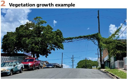
A combination of aging infrastructure and natural disasters contributes to below-standard reliability on the Island. Vegetation is a challenge for the distribution feeder system that can cause faults. These faults can be addressed in large by using reclose test cycles to, for example, burn the tree limb from the line and restore power.
New, more resilient feeder pole installations can also better withstand the impact of natural disasters. (see Figure 2).
Deployment Plan
In the first phase, the teams addressed the worst-performing feeders to make the most significant improvement possible on the reliability indices. This process required engineering and construction crews to work on and in different locations throughout the Island.
In the second phase, the team decided to use a regional approach making it possible to engineer and deploy reclosers more efficiently.
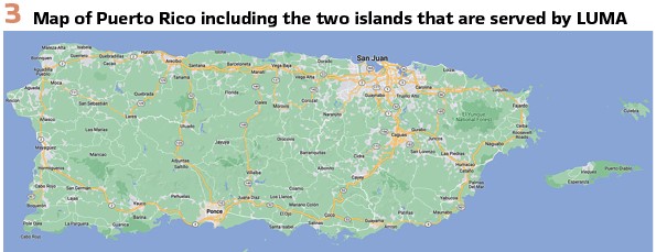
The team divided the Island into six regions. In each region, the team selects feeders for upgrades. The teams will complete a region and then move on to the next region. The engineering for a region is completed before the construction actions start.
The construction teams will remain in each region for 6 to 8 weeks and complete 50 to 60 feeder upgrades.
The regions are San Juan and Bayamon in the northeast, Mayaguez in the west, Ponce in the south, Caguas in the east and Arecibo in the northwest. (see Figure 3).
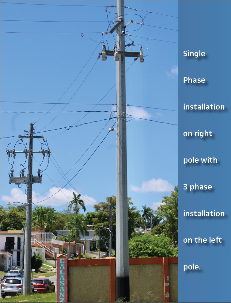
The distribution system automation plan includes the deployment of 3-phase and single-phase reclosers. Three-phase reclosers are installed in the main feeder line or trunks and heavily loaded lateral feeder lines. Single Phase reclosers and fuses are installed on the lateral lines.
The existing fuses in the main feeder trunks are removed to take advantage of the reclose functionality provided by the reclosers. The reclosers will significantly improve reliability in their ability to restore power for temporary faults automatically. Temporary or transient faults on distribution feeders are caused by vegetation and small animals and are the most common faults on overhead feeders.
LUMA Energy is, in addition verifying the existing feeder fuse coordination. The correct fuses are modeled, and values are communicated to operational teams for inspection and possible replacement or removal in the field. The fuse replacement program is synchronized with the recloser deployment program.
Installation if single-phase recloser on front pole and three phase recloser on the back pole. (see the Figure at the beginning of the article).
The LUMA teams meet daily to track the progress, plan activities, and report on the project. The teams include the following:
- Distribution Automation Reliability
- Planning
- Distribution Engineering
- Transmission and Substation Engineering
- Operations Support
- Operations
- Feeder Protection
- Substation Protection
- Permits
- Construction
- Quality Methods
- System Operations
- Asset Information
- Capital Programs
Recloser Deployment Steps
The responsible teams follow sequential steps to make the deployment of reclosers possible.
Substation Data Verification: The protection team is responsible for gathering the substation data in the field. The data include protection relay settings, current transformer, transformer, and substation circuit breaker in-service topology. The protection team required this data to effectively evaluate the coordination between substation breakers and the new reclosers.
Verify Feeder Loading Data: The feeder loading data in the current synergy models is based on a single-phase current measurement at the feeder head. The protection team requires phase load imbalance data for protection setting calculations.
The protection team provides the reliability team with locations to install load recording meters. The reliability teams record the loading of the feeder for a period that includes high and low loading conditions.
Site Selection: Site selection is a challenging and complicated task. The number of variables and stakeholders makes this task quite challenging. The location where the recloser must be installed must be at a constructible location that will fulfill the protection coordination and operational requirements. If the location is changed, the feeder’s protection settings must change.
The engineering team must select the initial site based on a preliminary protection coordination study and reliability improvement recommendations.
Site Verification: Engineering, operations, and construction teams perform site verification. The teams visit the identified sites to ensure a recloser can be installed at the selected location. Operations provide input to the engineering team for the best possible placement of reclosers concerning customers and operational experience. The construction crew must agree that the location is suitable for safe construction with adequate access for construction crews. All stakeholders must agree with the final site selection before engineering. The engineering team updates the feeder’s Synergi model with the reclosers’ final location.
Substation Settings: The protection teams gather all the substation data during field visits. It is essential to coordinate the reclosers with the feeder headend. The data include protection settings of the feeder headend relays and the power transformer data incoming feeder settings. The protection team uses the substation data to verify and update the current models.
Engineering: Engineering includes two components.
Preparing the Work Order Package (WOP) Documentation for Construction Crews
The WOP includes a scope of work, the location of the pole that the recloser must be installed on, pole replacement if required, and the construction standards for installing and removing equipment. The WOP includes a GIS map of the feeder, including notes indicating recloser, fuse installation, and removal locations.
The WOP provides the required materials for the construction work. Different WOPs are issued for three-phase and single-phase reclosers.
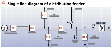
The engineering team produces a single line drawing of the feeder that indicates the location of the reclosers, fuse removals, voltage regulators, and 4kV step-down transformers and tie points. (see Figure 4).
Protection Coordination Study and Protection Settings
The distribution protection team used the final site-verified Synergy model for the protection coordination study. The protection team verifies the existing substation protection database data to the field-recorded substation protection settings and CT ratios.
The protection team developed a spreadsheet to determine the transformer inrush, the substation transformer damage curve, and per unit values of the MVA rating.
The field load data is of the utmost importance to verify the unbalance of the feeder phases. If the unbalance is unacceptable, system operations are tasked to balance the loading on the feeder.
The protection summary spreadsheet includes the transformer damage curve, high and low-side overcurrent protection, feeder breaker overcurrent settings, and recloser settings.
The spreadsheet summarizes all the relevant data and performs coordination and fault current reach checks. The protection team must consider the conductor sizes, as copper conductors are still in the distribution grid. The protection team provides the protection summary spreadsheet that includes the following additional information:
- Phase and ground fault protection coordination curves for the substation and feeder are in the spreadsheet
- Feeder circuit configuration Synergi model graphic
- Reclose cycle settings for the reclosers
- Hot Line Tag Settings
The substation protection team verifies the coordination study, makes final adjustments to ensure coordination with all upstream protection, and issues the final settings for the feeder.
Permitting: The local municipality must endorse to construction work through a permitting process.
The operation team provides a summary of the WOP as part of the application process.
Recloser Unit Testing: Operations teams do the reclosers testing. The reclosers are tested to LUMA standards that include vacuum, resistance, and phase angle as primary testing. The reclosers are operated as part of a mechanical test. Operations personnel apply protection settings and perform secondary injection testing.
Preconstruction: Preconstruction activities include excavation requests, material requisitions, scheduling with district operations, and obtaining approval documents from System Operations.
Construction: System Operations provide construction field crews with the WOP and schedule the date for construction. The field crew installs the 3 phase reclosers in a bypassed configuration. The field crews install the new poles if called for in the WOP. As part of the engineering process, a pole loading analysis is performed to assess if the existing pole can be used. The analysis includes adjacent poles.
Commissioning: The commissioning team is responsible for placing the recloser in service. The commissioning team will download the protection and radio settings to the devices, and the recloser is functionally tested, the metering is checked, communication is verified to the fleet management software, and SCADA operation is tested and verified before the recloser is put into service.
Quality Check: The quality team performed a quality check of the installation based on the WOP to ensure the field crews followed the appropriate construction standards. The site is assessed for cleanliness, and clearances are evaluated for safe operation.
SCADA Update: System operations will request SCADA to include the reclosers and FCIs. The customer counts will be updated and documented for the feeder.
Records and Mapping: If installed, the asset information team updates the GIS system with the reclosers, new poles, and transformers.
Project Closeout: The project manager collects all relevant project closeout documentation to complete the feeder upgrade project.
Feeder Protection Philosophy
Feeder Segmentation: Each feeder can have two three-phase reclosers and nine single-phase reclosers in the design.
The feeders are segmented using three-phase reclosers, single-phase reclosers, and fuses.
The main feeder trunks are segmented with two three-phase reclosers, each segment with no more than 500 customers.
Single-phase reclosers can be used on the main trunk toward the end of the feeder.
Single-phase reclosers are installed on all three phase laterals exceeding one mile in length with more than 300 customers.
Single-phase reclosers are installed on all single and two-phase laterals exceeding one mile in length with more than 100 customers.
Fuses must protect all remaining laterals.
No fuses are permitted on the main feeder trunks except for high-side fuses on step-down transformers.
Feeder Protection: The distribution feeders are protected using overcurrent and ground fault protection.
All overcurrent protection devices and fuses are coordinated.
The coordination includes the high and low-side transformer relays, the substation breaker, recloser A, recloser B, single-phase reclosers, and all fuses.
Single-phase reclosers have three standard configurations for deployment at 45kA, 65kA, and 100kA and will have one reclose cycle to test for temporary faults before lockout.
The following applies to three-phase reclosers:
- Three auto reclosing cycles to test for temporary faults
- Trip 3 phase trip on lockout
- Hot Line Tag is set to operate at TCC pickup without delay
- Detect an open source
- Use low-energy pulse testing if available
Communication and Data
LUMA energy leverages public cellular communication for the reclosers and FCIs due to its availability. LUMA Energy has a private VPN with a local carrier in Puerto Rico. The cellular communication links back to the LUMA enterprise are encrypted VPN tunnels for operational and non-operational data.
Data is communicated via future-proof IP-based communication systems back to the LUMA enterprise. (see Figure 5).
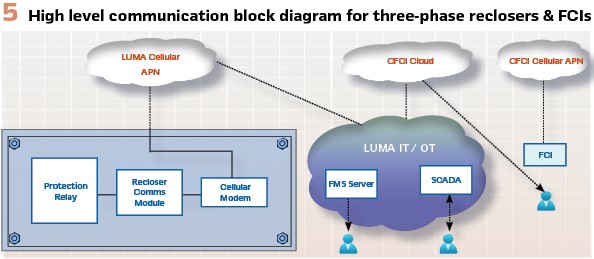
LUMA stakeholders will access non-operation data through fleet management applications for reclosers and FCIs. The non-operational data include per-phase loading, fault, and event data.
The non-operational data is essential for planning, reliability measurement, fault analysis, system awareness, and maintenance.
The LUMA cyber security and communication teams designed a secure and robust communication architecture.
The three-phase recloser communication and control module is designed to provide flexibility to LUMA in the future to use different radios. The antenna is mounted externally to the recloser and connected through weatherproof cables and connectors to the radio inside the control module. LUMA Energy plans to deploy its own Field Area Network (FAN). The FAN will likely not include public cellular. In the long term, LUMA Energy will have to change a large number of radios in the reclosers.
SCADA Integration
The reclosers and FCIs are integrated into the LUMA SCADA system. SCADA operators have remote control to open or close the reclosers, including fault and status indications of the three-phase reclosers. The FCIs will provide fault status indication. SCADA data will be communicated from the field devices using the DNP3 protocol.
The visibility of the reclosers and FCIs is essential to operators to speed up restoration actions. Field crews can be dispatched more accurately to where faults are located on the feeders.
Feeder Automation
LUMA Energy will automate distribution feeders in the future. The distribution feeders automation will be based on possible decentralized and centralized systems. The Fault Locate, Isolate, and Service Restoration (FLISR) systems will perform automatic switching actions. The FLISR system improves reliability due to extremely fast power restoration to customers not on non-faulted line segments. Each line segment has an alternate power source from a different substation.
FLISR Philosophy:
- FLISR loop automation systems will consist of two substation feeders from different substations inter-connected with an open tie recloser
- FLISR loop automation systems will consist of two substation feeders from the same substation connected to different substation transformers interconnected with an open tie recloser
- The substation feeders will be segmented with two down-line reclosers between the substation breaker and the open tie recloser
- The FLISR loop system must consist of at least five feeder line segments and not exceed six to maintain protection coordination
- Feeder line segments have approximately 500 customers or equivalent loading
- The FLISR loop system must support approximately a cluster of 2500 to 3000 customers, excluding customers on long overhead laterals
- Feeders must be predominantly overhead
- All recloser locations must have a reliable communication signal available
Maintenance
LUMA Energy will implement a condition-based maintenance plan for the communicating field devices. Non-communication devices will remain on a time-based maintenance plan.
The fleet management visualization applications will trigger required maintenance actions for communication field devices in the future.
Conclusion
LUMA Energy is confident that they will make a tremendous impact on improving the reliability of supply to their customers through the distribution automation actions that are underway.
Biographies:

Andre Smit – is an Executive Advisor at Quanta Technology and has over 33 years of experience in protection systems for power transmission and distribution systems. He served many different roles in the protection and control industry and comprehensively understands the market. He is an industry expert in distribution feeder automation systems. He led the development of new concepts leveraging IEC61850 to automate distribution feeders using wireless communication systems. He is the principal inventor of a distribution automation system and holds 7 US and international patents in the field. He pioneered deploying cellular base IEC61850 Direct Transfer Trip systems for remote distributed generation sites. He has deep subject matter expertise in generator protection systems

Camille Ocasio-Rodríguez is the Reliability Distribution Automation Manager at LUMA Energy. She has over 18 years of experience in Puerto Rico’s Electric Power Distribution System. Eng. Ocasio-Rodriguez earned her Electrical Engineering degree from the University of Puerto Rico in Mayaguez with Magna Cum Laude honors and is a professional licensed engineer. She is member of the Puerto Rico Professional College of Engineers and Land Surveyors, IEEE Power & Energy Society, and IEEE Women in Engineering. She served in many different roles in Puerto Rico’s electric utility and has a comprehensive understanding of the Distribution System. Her interests include protection systems and transforming Puerto Rico’s Electrical System into a Smart Grid.


