by I. Firdaus, M. Nurfaizi, V. Tobing, A. Perwita, PT. PLN (Persero), Indonesia, and B. Tahincioglu, OMICRON electronics GmbH, Austria
PT PLN (Persero) is Indonesia’s stateowned electric utility, responsible for the generation, transmission, and distribution of electricity. Substations operated by PLN serve as critical nodes in the power network, transforming highvoltage transmission into lowervoltage distribution to deliver reliable electricity from power plants to end customers. They play a vital role in controlling power flows and maintaining system stability, thereby ensuring continuous availability and high quality of supply to consumers. Meanwhile, the electric power industry worldwide is shifting toward more sustainable practices in response to climate change. Indonesia’s government has set ambitious targets, including a pledge to achieve carbon neutrality by 2060, mandating that PLN deliver reliable electricity in an environmentally responsible way. This requires adopting cleaner technologies and innovative grid solutions such as digital substations, which reduce carbon emissions without compromising system performance. PLN has initiated the modernization of its transmission network by deploying digital substations to replace or upgrade conventional substations. Digital substations integrate advanced protection, automation, and control (PAC) equipment with highspeed fiberoptic communications and IEC 61850 protocol for seamless data exchange.
By eliminating much of the copper wiring and reducing investment costs by approximately 29%, this approach significantly lowers both the physical footprint and carbon emissions of substation infrastructure. In addition, digital substations improve grid reliability by enabling realtime data monitoring, enhancing system visibility and accelerating fault detection and response.
However, adopting digital substation technology introduces a new paradigm for PLN’s engineers. Configuration and maintenance practices for protection and control in a digital substation differ significantly from those in conventional substations. In conventional substations engineers relied on wiring diagrams and devicespecific settings. For example, manually wiring relays and testing individual analog circuits. In a digital substation, these tasks become software driven: system configuration is managed through Substation Configuration Language (SCL) files and network settings, while testing is performed by simulating Sampled Values (SV) and GOOSE messages over Ethernet instead of secondary injection. Consequently, engineers must develop new skills in communication network management, IED configuration, and the use of specialized digital testing tools to fully realize the reliability benefits of digital substations.
This paper presents a case study of the Bekasi Digital Substation (GID Bekasi), Indonesia’s largest digital substation, and provides a comprehensive overview of its engineering design and postmigration maintenance practices. It outlines the challenges encountered, solutions implemented, and the maintenance methodologies developed at GID Bekasi, serving as a practical reference for the planning, deployment, and optimization of similar digital substation projects.
Digital Substation
In a digital substation, primary equipment measurements such as current, voltage, and switch positions are digitized directly at the source using MUs and transmitted over a high-speed communication network. This network, typically implemented with fiber-optic Ethernet and based on the IEC 61850 standard, enables the exchange of measured values, equipment status, and control commands between primary devices and secondary systems. By adopting this approach, digital substations significantly reduce the amount of copper cabling required between the switchyard and the control building, as illustrated in Figure 1. In addition, the IEC 61850 standard ensures interoperability among devices from different manufacturers and supports advanced reliability through real-time communication and standardized data models. This section provides an overview of digital substation concepts and architecture.
A. Architecture
The architecture of a digital substation is typically organized into three functional levels. Each level corresponds to a specific grouping of equipment and associated data flow within the substation automation system.
- Process Level: The process level includes the primary high-voltage equipment in the switchyard, such as current and voltage transformers (CT’s/VT’s), circuit breakers, disconnect switches. Analog signals and binary status inputs are acquired and converted into digital format at the source using MUs or switchgear control units. Real-time measurements and equipment statuses are transmitted as SV and GOOSE messages, enabling digital execution of functions like data acquisition, breaker monitoring, and command issuance.
- Bay Level: The bay level hosts Intelligent Electronic Devices (IEDs) responsible for protection, control, and monitoring of individual bays, such as transmission lines or transformers. These IEDs subscribe to SV and GOOSE messages from the process level and execute decision-making logic, including tripping, interlocking, and command issuance. IEDs also interface with the station bus to report status and receive supervisory commands
- Station Level: The station level includes supervisory systems such as the human–machine interface (HMI), SCADA gateways, time synchronization sources, engineering workstations, and data concentrators. This level aggregates information from all bay-level IEDs and provides a unified interface for local operators and remote-control centers. Communication occurs over the station bus, based on IEC 61850-8-1, which uses MMS (Manufacturing Message Specification) protocols for client–server communication
The IEC 61850 architecture defines two primary communication networks to support this hierarchy: the process bus and the station bus. The process bus connects process-level devices to bay-level IEDs, transmitting real-time SV data and fast control signals. The station bus connects bay-level IEDs to the station-level systems and also facilitates inter-bay coordination. In many implementations, these networks are deployed as separate physical Ethernet networks to enhance performance and cybersecurity. Alternatively, logical separation using VLANs can be employed over a shared physical network.
Case Study: Bekasi Digital Substation (GID Bekasi)
GID Bekasi is one of critical transmission backbones supporting system of West Java, Indonesia. Commissioned in the 1980s, the substation experienced significant system expansion and aging infrastructure over time. The addition of new bays and replacement of primary equipment eventually led to the deactivation of the high-impedance busbar differential protection scheme, leaving the busbar protection function unavailable. At the same time, PLN has been actively modernizing its grid infrastructure through the implementation of digital substations as part of its broader strategy to support sustainability and operational efficiency.
These conditions prompted the decision to upgrade GID Bekasi into a digital substation. Infrastructure development began in 2022, and the migration process was completed over the course of approximately one year, concluded in 2023. At the time of writing, the digital substation has been in operation for nearly two years. GID Bekasi operates at 150 kV and is configured with 4 busbars and a total of 27 bays, consisting of 16 line bays, 5 150/20 kV transformer bays, 4 bus coupler bays, and 2 capacitor bays. The subsequent sections provide an overview of the substation’s infrastructure, architecture, system components, and design approach.
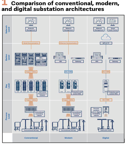
A. Infrastructure Change
Since the digital substation migration at GID Bekasi did not involve replacement of the main substation primary equipment, the physical layout of the high-voltage apparatus in the switchyard remained unchanged. However, the transition to digital architecture required the installation of additional marshalling kiosks (MK) in the switchyard to house Merging Units (MUs). These kiosks serve as the interface where analog signals from primary devices are converted into a digital format.
In parallel, new cable trenches were constructed with smaller dimensions compared to conventional designs. This reduction was made possible by routing only DC power and fiber-optic communication cables, eliminating the need for bulky copper control wiring. Furthermore, the number of control and protection panels in the control room has been significantly reduced, as shown in Figure 2. Overall, migration to a digital substation has led to a more efficient use of infrastructure, minimizing the physical footprint required for cable routing, panel space, and control building.
B. System Architecture and Communication Design
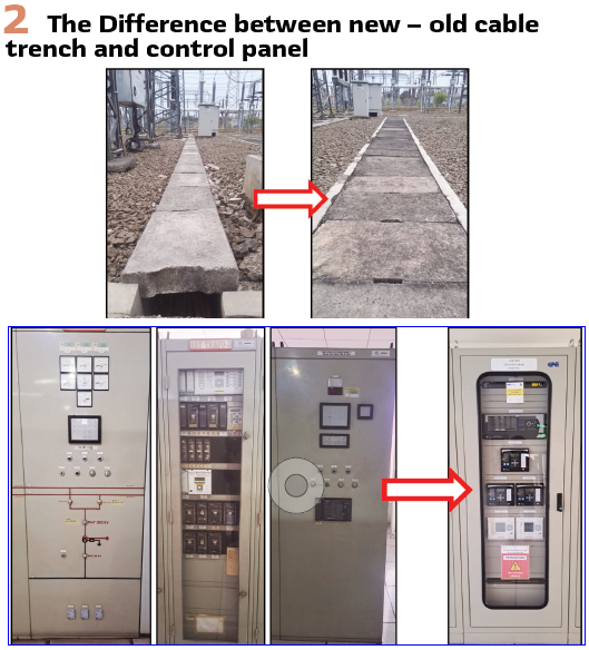
At the process level, analog current and voltage signals from conventional instrument transformers in the switchyard are digitized using GE MU320E MUs installed near the measurement source. These MUs convert analog measurements into SV data, status or position indications from primary equipment are captured by the MUs via binary inputs (BIs) and transmitted as GOOSE messages. Control and protection commands from IEDs are received by the MUs and forwarded to the respective primary equipment through copper wiring via binary outputs (BOs), enabling trip, close, or interlocking operations, as illustrated in Figure 3.
The number of MUs deployed in the system is based on the analog and digital signal requirements of each bay. Two MUs are assigned to each line, bus coupler, and capacitor bay, while three MUs are used for each transformer bay since it requires more CT inputs. This configuration ensures that all secondary circuits from CTs and VTs are terminated entirely within the switchyard. As a result, the burden on instrument transformers is significantly reduced, and the risk of open-circuit conditions is minimized.
Each MU is equipped with two fiber-optic (FO) outputs, assigned to Ring 1 and Ring 2 for network redundancy. These outputs are routed through two separate ducting paths to ensure a fully redundant communication link from the process level to the station level. The interface between the process and station levels is implemented using Outdoor Terminal Boxes (OTBs) and 8-core outdoor FO cables. This configuration simplifies troubleshooting and facilitates faster replacement in the event of a fiber failure or physical damage to the cable path.
At the bay level, the system utilizes GE S20 managed Ethernet switches to handle data traffic between IEDs, MUs, and the station level. In accordance with PLN protection standards, the protection architecture separates the Main Protection Unit (MPU) and Backup Protection Unit (BPU) into independent devices. The number of protection IEDs installed per bay is determined by the protection requirements and bay function, using GE Multilin and GE MiCOM series devices. Each protection IED is equipped with four communication ports: two dedicated for redundant SV links, and two others for GOOSE messaging and station-level communication.
For control and data acquisition functions, the substation is equipped with C264 Bay Control Units (BCUs). All IEDs are interconnected exclusively via fiber-optic cables to ensure electrical isolation and data integrity. As a result, copper wiring at the bay level is minimized and limited only to power supply lines and fail-safe alarm circuits. The layout of protection, control, and communication devices at the bay level is illustrated in Figure 4.
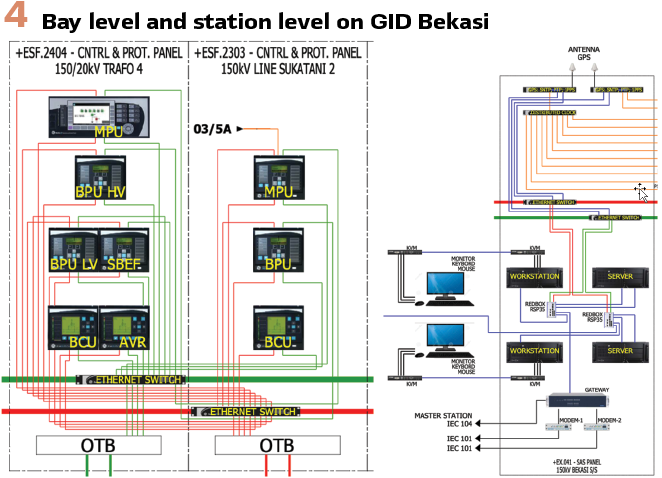
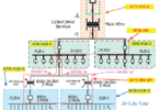
At the Station Level, GID Bekasi is equipped with two workstations for HMI, two servers, and a communication gateway to support SCADA integration and remote monitoring. A GPS-based time synchronization system ensures precise time alignment across all connected devices. The GPS antenna feeds two independent time sources, each associated with one of the redundant communication rings, and supports multiple synchronization protocols including SNTP, PTP, and 1 PPS. The use of PTP enables sub-microsecond synchronization accuracy, which is essential for the reliable transmission and alignment of SV across the network. The station-level layout is illustrated in Figure 3.
GID Bekasi employs the PRP as its network redundancy scheme, utilizing two physically separate communication rings, referred to as the red and green paths as shown in Figure 3. All IEDs are connected to both networks and operate in PRP mode, ensuring seamless communication with zero recovery time in the event of a path failure.
Devices that do not natively support PRP, namely single attached nodes (SANs) such as workstations and servers, are integrated into the redundant network using Redbox RSP35 devices. Ideally, each bay would be equipped with two independent communication rings to provide full redundancy. However, due to the large number of bays at GID Bekasi, this configuration would require at least 54 Ethernet switches, which is considered impractical. To optimize the design, a cross-ring configuration is implemented, where two adjacent bays share overlapping communication rings. In addition, the process level and station level are not physically separated using dedicated hardware. Instead, logical separation is achieved using VLAN tagging and segregation on the Ethernet switches. This approach maintains network isolation and reliability while minimizing the total number of Ethernet switches required.
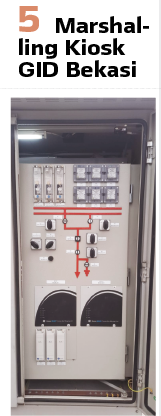
GID Bekasi also retains several conventional systems as backups to ensure operational reliability and safety. These include traditional control panels with mimic diagrams, hardwired equipment interlocks, lockout relays, Trip Circuit Supervisory (TCS) systems, Test-Block for testing, and VT selection switches for busbar voltage reference, which remain installed in the local control panels (MK) at the switchyard. These systems act as fallback mechanisms in the event of digital system failures and provide an extra layer of protection and control, as illustrated in Figure 5.
C. Engineering and Configuration of IEC 61850
The engineering process for GID Bekasi was carried out using a bottom-up approach. This method begins with the available physical IEDs, and the configuration is built according to their individual capabilities. Instead of designing the system based on a complete substation data model, each IED was configured separately, and functions were assigned case by case. As a result, the Substation Configuration Description (SCD) file, which ideally provides a comprehensive and centralized view of the substation, was not fully developed or consistently maintained. While this approach may be practical, it presents challenges in system testing, validation, and long-term maintenance.
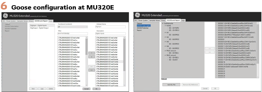
In the current implementation, protection IEDs and MU are configured using the Generic Logical Node (GGIO) for mapping digital signals. While functional, the use of GGIO is generally discouraged because it lacks semantic specificity. This makes the signals harder to interpret and reduces the clarity of maintenance tasks. Only the BCUs at GID Bekasi were configured using function-specific logical nodes in accordance with IEC 61850 recommendations, such as XCBR for breakers or CSWI for switch control, which offer better semantic meaning as shown in Figure 6.
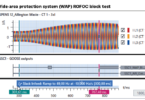
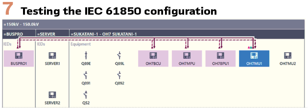
While traditional control and protection tests performed during migration confirm that intended functions are operational, they do not fully validate all digital signal configurations essential to the integrity of a digital substation. Specifically, it is important to verify that GOOSE messages and SV streams are correctly mapped to their target IEDs, and that VLAN segregation is properly implemented. Without this validation, issues such as orphaned signals (messages that exist on the network but are not defined in the configuration) or misrouted VLAN traffic can occur. These errors can result in increased network load, loss of critical signals, or even unintentional operations, making thorough digital signal testing a critical step in digital substation deployment. At GID Bekasi, this validation was conducted after the migration was completed, using specialized tools capable of visualizing IEDs and their network interactions. These tools were connected to the process bus Ethernet switch and used to assess IEDs. The tests verified that GOOSE signals were correctly configured and that VLAN segregation was functioning as intended. This process helped confirm the integrity of the deployed configuration and serves as a benchmark for future equipment replacement or system expansion in digital substations.
As shown in Figure7, the test results confirmed that there were no orphaned GOOSE signals present in the system. VLAN segregation was functioning correctly, and all IEDs were exchanging information accurately according to their configured roles. This validation provided assurance that the configuration was properly implemented. However, due to the unavailability of a complete SCD file, the validation was conducted using individual CID (Configured IED Description), files from each relay. As a result, the test could not confirm the SV paths, since SV configuration details are not included in most CID files.
D. Maintenance Practices
Since test blocks are still available in the MK kiosks at the switchyard, conventional testing using analog current and voltage signals remains possible. While this method can be used, it also includes the MUs in the test path and does not isolate the protection IEDs. Moreover, there is a risk that the injected signals may affect other relays that subscribe to the same SV stream.
For verifying the response of a specific IED, direct SV injection is required, along with GOOSE message subscription to observe the IED’s behavior. To support this, each bay at GID Bekasi has been configured with a dedicated setting at the Ethernet switch port. This configuration allows VLAN filtering for SV and GOOSE messages to be selectively adjusted, enabling targeted testing of IEDs within the bay.
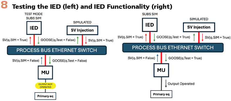
IEC 61850 Edition 2 introduces specific testing features to facilitate safe and efficient maintenance. Logical nodes can be set to different operational modes, such as ON, Test, and Test/Blocked, Blocked and OFF. In the Test mode, IEDs processes inputs and generate outputs with a test-quality flag (q.test=true). Subscribers in normal operation mode ignore these flagged messages, ensuring testing isolation. The Test/Blocked mode extends this functionality by internally executing protection algorithms but preventing actual tripping outputs, safeguarding against unintended physical operations. Furthermore, Edition 2 provides a Simulation mode (LPHD.Sim), allowing IEDs to selectively subscribe to simulated SV and GOOSE messages injected by test equipment, rather than actual process data.
With this configuration, IEDs can be tested based on the intended objectives. To specifically test an IED without engaging primary equipment, the IED is set to Test mode and SV simulation mode. This configuration enables the IED to subscribe exclusively to the simulated SV from the test equipment, and only the test equipment receives the relay’s response. For functional testing including primary equipment (such as breaker trip and reclose), the IED is configured to ON mode combined with SV simulation mode. In this scenario, the IED subscribes to the SV from the test equipment but still sends operational signals to the MU, enabling breaker operation as depicted in Figure 8.
With this method, testing can be conducted safely and selectively without affecting the operation of other equipment, providing precise validation of both individual IEDs and complete protection schemes. Additionally, due to the integration of MUs, supplementary testing is required to verify their performance by comparing the original analog signals with the digitized outputs produced by the MUs. This includes validating the timing accuracy from the reception of GOOSE messages to the generation of output signals, and vice versa, to ensure proper coordination and response within the system.
Recommendations and Future Prospects
The digital transformation of GID Bekasi demonstrates the practical viability and benefits of implementing IEC 61850-based substations within Indonesia’s electrical transmission. Building on this experience, future developments can focus on improving engineering practices and strengthening standardization.
First, future projects should prioritize top-down engineering approaches using complete and standardized SCD files. This will improve interoperability, simplify commissioning, maintenance, and future expansions. Standardizing the use of function-specific logical nodes across all devices is also essential to improve semantic clarity and support more efficient testing and diagnostics.
Second, the adoption of digital signal validation tools should become a standard part of commissioning and maintenance procedures. These tools can prevent issues related to orphan signals or VLAN misconfigurations, which are not typically visible through conventional testing. Training programs should be expanded to ensure engineers are fully equipped with the skills required for digital system engineering, configuration, and advanced diagnostics.
Lastly, future substation projects should integrate digital transformation plans with infrastructure planning, ensuring the optimal use of space, reduced wiring complexity and footprint, and increased reliability. Pilot projects like GID Bekasi serve as valuable references and should be leveraged for continuous improvement and knowledge sharing across PLN’s organization and with other utilities.
Conclusion: The implementation of GID Bekasi as Indonesia’s largest digital substation represents an important step in PLN’s effort to modernize its transmission network. Using a bottom-up engineering approach, the project successfully integrated IEC 61850-based communication into an existing substation without replacing primary equipment. The experience illustrates that even a semi-digital migration can deliver benefits in reliability, efficiency, and infrastructure optimization.
Several technical lessons were gained from this project. The validation of digital signals was shown to be essential to ensure correct operation and prevent misconfiguration. The use of VLAN segregation, PRP redundancy, and IEC 61850 Edition 2 testing modes also played an important role in maintaining system reliability and flexibility during maintenance. Engineering challenges such as the use of generic logical nodes and incomplete SCD files highlight the importance of adopting standardized configuration practices in future projects.
This case study provides practical insights and serves as a reference for other utilities planning to implement digital substations. The methods and experiences from GID Bekasi can help improve engineering, testing, and maintenance strategies, contributing to more reliable, efficient, and scalable substation systems.
Biograpies:

Idam Firdaus is a Protection Engineer with over nine years of experience at PLN, Indonesia. He started his career as a Protection Engineer in 2016 and has been engaged in commissioning and testing protection relays, contributing to the reliability of transmission and substation systems. Currently, he serves as Manager of the Transmission and Substation Services Unit, where he leads the maintenance of power transformers, transmission systems, and protection relays. In 2025, Idam completed his master’s degree in engineering physics at Institut Teknologi Bandung with cum laude honors, focusing his thesis on the development of supercapacitors.

Muhammad Muflih Nurfaizi, works as a Protection Transmission Engineer at PT PLN (Persero). He earned his bachelor’s degree in electrical engineering in 2019 and is currently trying hard to graduate from his master’s program in Chemical Engineering. Outside of work and study, he is passionate about coding and enjoys exploring nature.

Victor Lumban Tobing works as a Protection Transmission Engineer at PT PLN (Persero). He graduated in 2013 from a vocational high school specializing in electrical engineering and began his career as a substation operator. Outside of work, he enjoys playing table tennis and is currently developing his expertise in DC ground fault detection.

Ade Yoan Perwita graduated with a Diploma in Electrical Engineering in 2019 and began her careers as Protection Transmission Engineer at PT PLN (Persero). She has a strong passion for music and adventure—singing, playing in a band, and traveling are hobbies that bring joy and balance to her life. While pursuing her professional career, she is also embracing the role of a homemaker, continuously learning to juggle work responsibilities and family life.

Burak Tahincioglu received his bachelor’s degree from Electrical & Electronics Engineering at Mersin University, Turkey in 2009. He worked as a protection and control engineer at national transmission system operator of Turkey (TEIAS) from 2011 until 2019. He was part of the team commissioning the very first IEC 61850 based substations in Turkey. He contributed to the national defense plan of Turkey to be nation-wide standardized and released for ENTSO-E.
In 2019 he joined OMICRON in Austria, as product specialist for IEC 61850 substation automation system (SAS) testing solutions. He works on IEC 61850 SCL Engineering topics for supporting utilities in this area. He is member of CIGRE Working Group B5.86 PACS interfaced asset management and condition monitoring using innovative technologies and has various articles published at DPSP, CIRED, PAC World, Saudi Smart Grid Conferences.