by Alexander Apostolov, PAC World, USA
Some of the main characteristics of Smart Grids are the high level of penetration of distributed energy resources (DERs) and the requirements for improved reliability of the electric power system under different abnormal conditions. The DERs are of different sizes and types and are being connected at all different levels of the electric power system – transmission, distribution and low voltage. This introduces significant challenges for protection systems at the transmission and distribution level of the system which need to be considered in the engineering of the protection devices and systems.
In order to remain in service following a short circuit fault the DERs need to be able to withstand the voltage drop until the fault has been cleared by the protection and the circuit breaker. Considering that the protection operating time depends on the type of protection, location of the fault, type of fault and fault parameters, it is clear that these factors need to be analyzed in order to identify the requirements for improvement in the fault clearing time.
IEC 61850 is the dominant communications protocol recognized as one of the cornerstone technologies for the Smart Grid that brings significant benefits to the industry and allows the more efficient integration of devices of different types into systems. The characteristics of the high-speed peer-to-peer communications defined in the standard can be used in protection schemes to reduce the fault clearing time.
The use of GOOSE messages in communications-based protection schemes at the transmission level will have an impact on the DERs through the use of accelerated protection schemes based on what is known as a wide-area GOOSE
Ride-through Characteristic
Distributed generators are being typically connected to sub-transmission or distribution systems. The definition of such systems varies between utilities and in some cases systems with voltages as high as 138 kV may be considered as distribution. The addition of distributed generators has a significant effect on the system. The levels of short circuit currents, the dynamic behavior of the system following such faults, the coordination of protective relays are affected and have to be considered in the selection of the protection system. Line protection settings and criteria should take into account in-feed effect, possible power swings and generator out-of-step conditions.
The increased fault clearing times that are caused by the in-feed effect of a distributed generator may not be acceptable to customers with sensitive loads. The voltage sag is experienced not only by users on the faulted feeder, but also on the adjacent feeders, connected to the same distribution system.
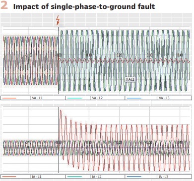
Figure 2 shows the areas of impact of voltage sags or swells on sensitive equipment and demonstrates that the impact depends on two characteristics. The first characteristic of a voltage sag – the depth – is a function of the type of fault, fault location and the system configuration. It will also be affected by the state of the distributed generator – if it is in service or not. Single phase-to-ground faults lead to voltage sag in the faulted phase and to voltage swell in the healthy phases. The level of voltage increase is also affected by the grounding of the interface transformer and should also be taken into consideration.
The same two characteristics of the fault also have an impact on the ride-through capability of the DER. Figure 3 shows an example of a ride-through characteristic.
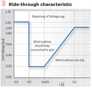
The ride-through characteristic includes two areas defining the required response of the DER when a short circuit or another abnormal condition occurs.
The first area is the ride-through area when for a short period of time after the fault inception and depending on the level of the voltage drop the DER should stay connected to the grid.
The second area is where the DER can trip if the voltage drop is deeper or lasts longer.
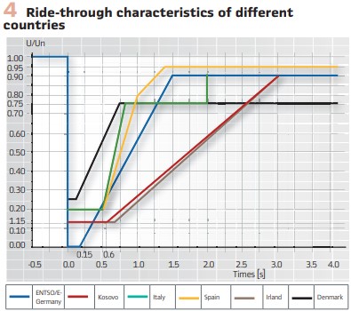
The ride-through characteristics are different for different countries, as shown in Figure 4.
The voltage drop is something that we cannot control, but we have to study in order to be able to predict or estimate the effects of different faults on the sensitive equipment. The second characteristic of the voltage sag – duration – is the parameter that we can control by properly applying the advanced features of multifunctional protection relays.
The distributed generator interconnection protection is subject to many papers, as well as standardization work, such as IEEE P-1547. It is clear that the location of the fault will have an impact of the fault clearing time and coordination problems. This depends more specifically on the type of distributed generator and its interconnection with the electric power system.
However, it is not only the distribution feeder protection that needs to be accelerated. When a short circuit fault occurs on a transmission line at a substation with DERs connected at the distribution level, the voltage drop caused by the fault needs also to be considered in the analysis of the performance of the DER and its ability to ride through the fault.
When the fault is in Zone 2 of the protected transmission line (especially on shorter lines) the time delayed trip will depend on the time delay setting which in many cases is in the range of 300 – 400 msec. Such a delayed trip will result in the duration of the voltage sag experienced by a DER in the tripping area of the ride-through characteristic. An accelerated protection scheme can significantly reduce the fault clearing time and bring it within the stay connected area of the characteristic, but we also need to consider what else we can do to improve it.
When we think about reducing the fault clearing times for faults in Zone 2, the first thing that we can look at is the time delay of its operation. If we look at the numbers, this time delay is required to ensure that the zone 2 is not going to trip for faults in Zone 1 of an adjacent line. This means that the time delay has to be based on the:
- Operating time of Zone 1
- Breaker opening time
- A safety margin based on the accuracy of the time measuring element
At the time of electromechanical protection relays the Zone 1operating times were not very fast, the accuracy of the Zone 2 timers was not very high, while at the same time the breakers’ opening times were not very fast either. This can explain the selection of 300-400 milliseconds as the time delay setting.
However, now we live in a very different world where all these numbers have gone down significantly. Many modern distance protection relays have Zone 1operating times of less than one cycle, while the accuracy of the timers is in the range of 1 millisecond. Many breakers at the transmission level have two or three cycles opening time with one cycle breakers used in many cases as well. If we add these numbers, it becomes clear that we can set the time delay of the Zone 2 protection element to less than 100 milliseconds, which if we consider a two-cycle breaker will give us a full clearing time for a Zone 2 fault of less than 160 milliseconds which will support the right through of the DER.
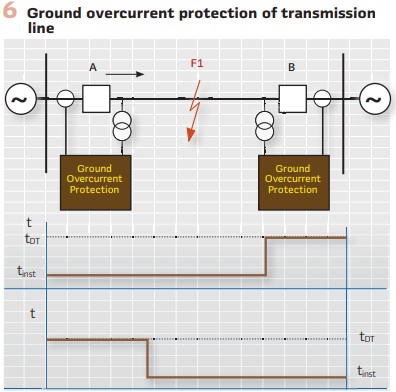
The problem with using distance protection in systems with high penetration of inverter-based resources Is that they do not produce sufficient fault current which may lead to a failure of the distance elements to operate. The good news is that most of the short circuit faults in the electric power system are single-face-to-ground and when the power transformer that is used to connect the inverter-based resources to the grid is grounded wye / delta, there is sufficient zero sequence current to operate the directional ground overcurrent elements that are commonly available in modern transmission line protection devices. That is why a low hanging fruit in improving the protection of transmission lines is by using directional step ground overcurrent protection. An instantaneous element can be used to protect for faults on 80-90% of the line, while the remaining 10-20% will be protected by a definite time delayed element with the time delay setting in the range of 100 milliseconds, which will support the ride-through of the DERs.
Accelerated Distance Protection Schemes
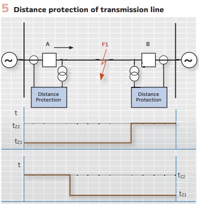
Conventional zone distance protection (Figure 5) does not provide instantaneous tripping for all faults on the protected transmission line due to the fact that typically the last 20% of the protected line is covered by the Zone 2 element that typically operates with a time delay of 300-400 ms.
Communications based distance protection schemes, where a signal from the protection relay at one end of the line is sent to the protection relay at the other end of the line, allow considerable improvement in the overall fault clearing time for any fault within the zone of protection, and they do not require high-speed communications essential for line differential protection. This is because the signaling channel in these distance protection schemes only transmits simple ON/OFF data (from a local protection device) to the remote end protection device that is used to accelerate in-zone fault clearance or prevent operation for external faults.
These accelerated teleprotection schemes can be grouped into three main operation modes: Intertripping, Permissive and Blocking. The protection function that sends the permissive or blocking signal to the remote end determines the type of scheme used.
If this is a distance element, we usually talk about Permissive Underreaching or Overreaching schemes, and Blocking schemes. If a directional element is used to initiate the transmission of a signal to the remote end of the protected line, it is a Directional Comparison scheme. Directional comparison schemes can be Permissive or Blocking, with directional elements initiating the signal transmission and providing the supervision at the receiving end.
There can be several types and combinations of permissive and blocking logic implemented in protection schemes.
In Inter-tripping, (direct or transfer tripping) applications, the command from one end of the line is not supervised at the remote receiving end by any protection relay and simply causes a remote breaker trip operation. Since the received signal is not checked by the remote protection device, it is absolutely essential that any noise on the signaling channel is not seen as being a valid signal. In other words, an inter-tripping communications channel must be very secure.
An example of direct or transfer trip is when a line breaker at one end of the line fails to operate, and a signal is sent to trip the breaker at the other end of the line.
In Permissive applications, tripping at the remote end of the line is only permitted when the command coincides with a protection operation at the receiving end. Since this applies a second, independent check before tripping, the signaling channel for permissive schemes does not have to be as secure as for inter-tripping channels.
An example of permissive tripping is Zone 2 directional permissive overreach transfer tripping (POTT), where a fault is in Zone 2 of a relay and operation of the relay is accelerated by receiving the Zone 2 starting signal from the other end of the line.
In Blocking applications, tripping is only permitted when no signal is received, but a protection operation has occurred.
In other words, when a command is transmitted, the receiving end device is blocked from operating even if a protection operation occurs. Since the signal is used to prevent tripping, a blocking channel must be fast and dependable. An example of blocking tripping is Zone 2 directional blocking tripping, where a fault is in Zone 2 of a relay and operation of the relay is accelerated by not receiving the Zone 3 (reverse looking) operating signal from the other end of the line.
Weak Infeed Logic
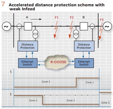
One of the concerns of the protection community related to the high levels of penetration of inverter-based energy resources is that when a fault occurs on a transmission line, some distance protection elements will operate with a delay, and as a result, expose the DERs` in the neighboring system to lower voltage levels that may be in the tripping zone of the ride-through characteristic. For example, with the distance protection scheme shown in Figure 7, a fault at F1 will be seen by the protection relays at both ends of the line in Zone 1 and it will be cleared without any significant time delay. For a fault at F2 it will be seen in Zone 1 by the relay at end B, but in Zone 2 by the relay at A, thus leading to a delayed tripping of that breaker.
Accelerated transmission line protection schemes are typically used to reduce the fault clearing time for faults in the Zone 2 of the distance protection. However, such schemes require the Zone 2 distance element at both ends of the line to operate, which results in the sending of a permissive signal to the remote ends as described above. In this case the fault clearing time will depend on the Zone 2 starting time and the communication channel delay, which will be much faster than the Zone 2 tripping time.
If end B of the transmission line (Figure 7) is connected to a substation in an area with a high penetration of inverter-based distributed energy resources, for a fault at F2, it will be seen in Zone 2 of the relay at line end A with a strong source and send the permissive signal to the weak end relay B.
Because of the weak source at B, the fault may not be seen by Zone 1 or Zone 2 of protection relay B because of the low fault current level, so a traditional directional POTT scheme will not operate.
To solve this problem, weak infeed logic is implemented by using a permissive Zone 2 trip signal from A to operate relay B if the reverse looking Zone 3 of the protection at B has not operated, indicating that the fault is on the protected line. The weak infeed logic will trip breaker B and then send a transfer trip signal back to A for permissive accelerated Zone 2 tripping at A.
In this case the fault clearing time will be increased by the communication time from B to A, but will still be much faster than the Zone 2 tripping time at A.
Considering that typically a Zone 2 time delay is in the range of 300-400 ms the operating time of this logic will be much faster, around 70-80 ms, which will keep the fault clearing time within the most stringent 160 ms tripping delay specification in the IEEE 1547 inverter ride-through characteristic.
Wide Area IEC 61850 GOOSE
While the benefits of accelerated transmission line protection schemes have been known for many decades, their implementation typically has been limited by the fact that they require a communication channel, which can be quite expensive.
The good news is that developments in the IEC 61850 standard can help solve the requirement for low latency end-to-end communications between substations.
The IEC 61850 GOOSE message was designed for peer-to-peer communications within the substation over a LAN, and because of that, it uses a three-layer stack and MAC multicast. This is not suitable for messages that need to be sent over a wide area network.
For that reason, additional features are required to support GOOSE transmission over wide area networks. Some network routers designed for use in the power utility field provide features to wrap GOOSE messages into IP packets and transmit them over a WAN.
GOOSE over MPLS
Multiprotocol Label Switching (MPLS) is a packet-forwarding technology that uses labels to make data forwarding decisions. MPLS networks became the focus of evaluation and deployment in many power utilities since they provide connectivity for all kinds of services within a utility, not just protection.
With MPLS, the Layer 3 header analysis is performed only once (when the packet enters the MPLS domain). Label inspection drives subsequent packet forwarding. In the traditional 7 layer OSI model, datalink Layer 2 includes protocols, such as Ethernet, which can carry IP packets, but only over simple LANs or point-to-point WANs.
The network Layer 3 includes Internet-wide addressing and routing using the Internet Protocol (IP). MPLS operates between these traditional layers, providing additional features for the transport of data across the network. Because of that, MPLS is sometimes called a “Layer 2.5 networking protocol.”
This technology allows the engineering of paths between substations that can transport layer 2 traffic through the WAN, thus effectively extending the LAN into remote substations. IEDs communicating via GOOSE can therefore exchange information with remote devices, just as if they were connected to the same local network.
R-GOOSE
The technical report IEC 61850 90-5 Use of IEC 61850 to transmit synchrophasor information according to IEEE C37.118 is the document that also defines the methods for transmitting GOOSE messages over wide area networks based on IP solutions. This report selected UDP/IP as the option to transmit data over WANs. The GOOSE messages based on this technology became known as Routable GOOSE or R-GOOSE.
The Internet Protocol (IP) is a Layer 3 protocol. The Network layer adds the concept of routing above the Data Link layer.
When data arrives at the Network layer, the source and destination addresses contained inside each frame are examined to determine if the data has reached its final destination. If that is true, this Layer 3 formats the data into packets delivered up to the Transport layer.
The IP allows the routing of data packets (IP packets) between different networks over any distance.
The User Datagram Protocol (UDP) is a Transport Layer 4 network protocol. While TCP (Transmission Control Protocol) is a connection-oriented protocol that first requires establishing communications between a client and a server, UDP is connectionless, which makes it more suitable for GOOSE communications. UDP network traffic is organized in the form of datagrams.
A datagram comprises one message unit. The first eight (8) bytes of a datagram contain header information and the remaining bytes contain message data.
A UDP datagram header consists of four (4) fields of two bytes each:
- Source port number
- Destination port number
- Datagram size
- Checksum
The UDP checksum protects the message data from tampering. The checksum value represents an encoding of the datagram data calculated first by the sender and later by the receiver. If the UDP checksum does not match, it will indicate that the data has been tampered or corrupted during transmission. In UDP, the check sum is optional as opposed to TCP where it is mandatory.
The many working applications of the IEEE C37.118 protocol confirm that the use of UDP for the streaming of synchrophasor data is a proven method that can also be used for the routable GOOSE. Considering the importance of the check sum as a cyber security tool, IEC 61850 8-1 Edition 2.1 defines it as mandatory for IEC 61850 implementations.
Biography:

Dr. Alexander Apostolov received his MS degree in Electrical Engineering, MS in Applied Mathematics and Ph.D. from the Technical University in Sofia, Bulgaria. He is Principal Engineer for OMICRON electronics in Los Angeles, CA. He is an IEEE Fellow and Member of the PSRC and PSCC. He is past Chairman of the Relay Communications Subcommittee, serves on many IEEE PES WGs. He is a member of IEC TC57 WGs 10, 17, 18, 19, Convenor of CIGRE WG B5.69 and member of several other CIGRE B5 WGs. He is a Distinguished Member of CIGRE. He holds 4 patents and has authored and presented more than 500 technical papers. He is an IEEE Distinguished Lecturer and Adjunct Professor at the Department of Electrical Engineering, Cape Peninsula University of Technology, Cape Town, S. Africa. He is Editor-in-Chief of PAC World Magazine.