by Bogdan Kasztenny and Mangapathirao (Venkat) Mynam, Schweitzer Engineering Laboratories, Inc. USA
Most protection principles we use today have remained relatively unchanged since their introduction. A protection engineer from the 1920s would recognize transformer differential logic described in an instruction manual of a modern microprocessor-based relay. What has changed dramatically are the devices that implement these protection principles. Relays based on early semiconductors replaced electromechanical relays in the 1970s only to be replaced a decade later with microprocessor-based relays. We have witnessed improvements in reliability, dramatically expanded functionality, reduction of size and cost, and many other enhancements. This technological progress – including expansion of functionality adjacent to protection – does not change the fact that protective relaying became a mature field.
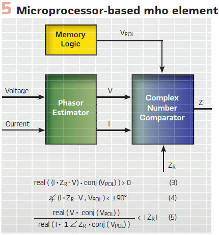
At the heart of any distance element is the “IZ – V” operating signal, polarized with voltage (mho) or current (quadrilateral).
As we unsurprisingly began focusing more on life-cycle challenges, cost, and ease of use, we gradually started taking protection for granted. We accepted that the performance of modern relays came close to an unbreakable ceiling, and too often we dismissed improvements as diminishing returns. After all, we have made considerable progress over the last five decades since electromechanical relays ruled the world. Or have we?
This article shows that progress sometimes takes detours. We discuss how early microprocessor-based relays gave up implementation methods of static relays not because they were inadequate, but because they needed a new implementation method that would fit the processing power available at the time. We argue that going back to analog principles and implementing them in digital relays allows us to unlock performance that is otherwise hidden from us.
A Brief History of Distance Elements
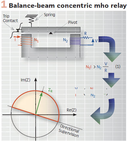
Imagine it is the late 1920s and you are a protection engineer working on line protection. Overcurrent relays and fuses are commonly used, but they are not very selective. Pilot wire schemes have just been invented, but they are expensive. Would it not be beneficial if one could devise a relay that sees faults on the line but not beyond the remote bus, yet uses only local measurements? This would be a significantly better version of a current-based relay but with reach that is much less dependent on system strength and fault resistance. All you have, however, are iron cores, copper wires, coils, resistors, contacts, springs, and bearings. Vacuum tubes are not reliable, and semiconductors are not yet invented. Your solution may involve a balance-beam relay (Figure 1). The beam tilts toward closing the contact and tripping the breaker if the ampere turns from current overcome the ampere turns from voltage. The V-over-I term in (2) is the apparent impedance, and you just invented a nondirectional distance relay. To make the scheme directional, you supervise it with a directional relay. You allow the users to set the reach by adjusting the R, N1, and N2 parameters.
You may improve on your original invention by using a cylinder unit relay (Figure 2). The cylinder rotates toward closing the contact and tripping the breaker if the torque created by the polarizing and operating signals is positive. You shape the operating signal to be proportional to I • ZR – V and the polarizing signal to be proportional to V. As a result, you obtain a directional mho operating characteristic. The characteristic is a circle that stretches between impedance 0 (relay location) and ZR. ZR is the distance relay reach that users set by adjusting turns and resistances in your new design.
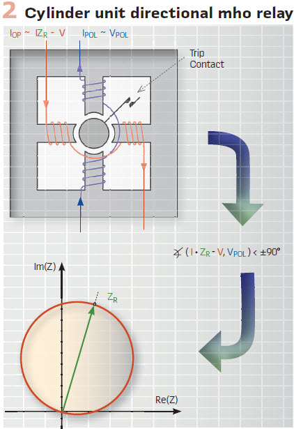
The directional mho operating characteristic is a circle with several advantageous features: it allows load to come close to the characteristic boundary; for external resistive faults, the characteristic bends away from the apparent impedance that intrudes due to infeed effect; the characteristic is directional on its own. But is the mho circle special? Would the industry adopt your design if the resulting characteristic was an ellipse? Absolutely. Fixed reach is the key advantage, not any specific characteristic. Any reasonable shape would work (we now insist on specific shapes for coordination of stepped-distance and pilot schemes).
At the heart of any distance element is the “IZ – V” term or the operating signal, polarized with voltage (mho) or current (quadrilateral). Typically, distance comparators use the 90-degree limit angle originating from electromechanical relays. As a protective relay pioneer once said, “V over I does not make a distance relay.” Our industry has been improving distance relays since their introduction in the 1940s, including better polarization methods to address bolted close-in faults, phase selection, directionality, load blinders, reactance elements, and so on.
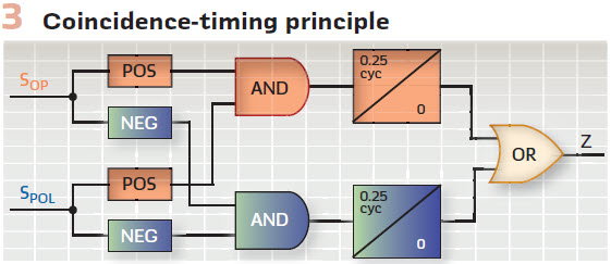
Imagine it is the 1970s and semiconductor devices (diodes, transistors, and operational amplifiers) have become reliable enough for protection applications. Now you can implement various characteristics by checking the angle between operating and polarizing signals through coincidence timing (Figure 3). Two sine waves are 90 degrees apart if they have matching polarities for a quarter cycle. In your distance relay, you replace torque-based electromechanical comparators with analog coincidence timers. Because the latter are smaller, lighter, and cheaper, you can use more of them and shape sophisticated operating characteristics. A mho circle is now a choice, not a constraint.
You also realize you are not shackled anymore to the inherent inertia of electromechanical relays, but you can explicitly control the degree of filtering and speed in your solid-state designs. Protective relays have become much faster: perhaps too fast for their own good. Transient simulators are still in their infancy. Fault recorders are not widely available. Static relays have been designed for speed without necessary transient testing. Predictably, security has suffered. High component failure rates, lack of self-monitoring, and electromagnetic interference (barely recognized as a problem at the time) have only added to the challenges. Fast but fragile is a fitting label for the static relay generation. Static relays would have matured with investment fueled by their advantages, but emergence of the microprocessor-based relay with an explosion of functionality arrested the static relay generation.
Imagine yourself in the early 1980s. You have access to analog-to-digital converters, but you can sample just several times a cycle. You have access to a microprocessor but the available processing power allows running only so many instructions in a power system cycle. Can you emulate static relays the same way static relays emulated the angle comparison of electromechanical relays? Absolutely not. You need a new method. You need to slow down the flow of information to keep up. If you barely satisfy the Nyquist principle and sample just a few times a cycle, you need to heavily filter the input voltage and current. The output from the anti-aliasing filter is therefore very clean, and you can represent the near-sine waves with phasors, even if calculated from just a few samples per cycle. Phasors allow you to slow down the flow of information to any arbitrary rate you need in order to keep up. You can calculate phasors just once or twice a cycle and still claim instantaneous protection operation. Once you have the phasors, you can implement the tried-and-true protection principles through calculations (Figure 5). The synthesis method becomes an implementation method. You can shape the directional mho characteristic by using torque (3), angle (4), m-calculation (5), or any other equivalent equation. Once you have the phasors, it is just mathematics from there.
Do not underestimate the role of numerical optimization in the early microprocessor-based relays. For example, the m-calculation (5) does not improve performance, it still just plots the mho circle. It is not simple either, but it is attractive because when calculated once, the m-value can be efficiently used in a multizone relay by comparing it to the reach setting of each zone.
The Good and Bad of Phasors
Phasors have served us well, from Steinmetz’s introduction of using complex numbers for analysis of alternating current (ac) networks in 1893, through their use as operating quantities in microprocessor-based relays a century later, to the use of synchrophasors for monitoring and controlling power systems today.
Phasors were the convenient step that allowed early microprocessor-based relay designers to shape protection characteristics while slowing down the flow of information for processing. Using the same language (phasors) to design, implement, and analyze relays is another advantage of phasors. Phasors will continue to play an important role in microprocessor-based relays because they are sufficient for simple functions, such as overcurrent, over- and undervoltage, or even distance elements if the speed is not critical and one-cycle operation is acceptable.
Over the years, we have probably seen some 1,000 unique papers on how to calculate better phasors for protection. These algorithms constitute a dozen or so distinctive families of methods, from plain Walsh, Cosine, and Fourier algorithms to Kalman filters and neural networks. We want accurate phasors fast, despite a wide range of interfering signals, including decaying oscillatory components, decaying dc offset, harmonics from nonlinear loads, effects of current transformer saturation, and capacitively coupled voltage transformer (CCVT) transients.
Practical relay designs recognize that the accurate phasors fast mantra is an oxymoron and use plain Fourier or Cosine filters. Ultimately, phasors are obtained through filtering. One cannot simultaneously reject noise with a frequency spectrum close to the signal yet have a fast response to step changes in the signal. When researchers embarked on the quest for a perfect phasor estimator, relay designers tried running “slow” and “fast” phasors in parallel (full-cycle and half-cycle windows, for example) and using them together based on a set of conditions. This too was largely a misdirected effort. Slow phasor estimators, when subjected to large multiples-of-pickup cases, respond fast. Fast phasor estimators must be secured because of their higher transient errors, and as a result, they may not respond at all for small multiples-of-pickup cases. We seem to be chasing the accurate phasors fast tail.
The main feature of a phasor is that it intentionally adds a band-pass lens when looking at the signal. Phasors reject information other than a narrow band around the power frequency and by doing so impair our ability to see events with more fidelity.
A different solution is not to suppress noise up front but to allow the wide-frequency spectrum in, understand the high-fidelity information better, and use it for speed while securing the protection logic against noise. We explain this philosophy next.
Samples Versus Phasors
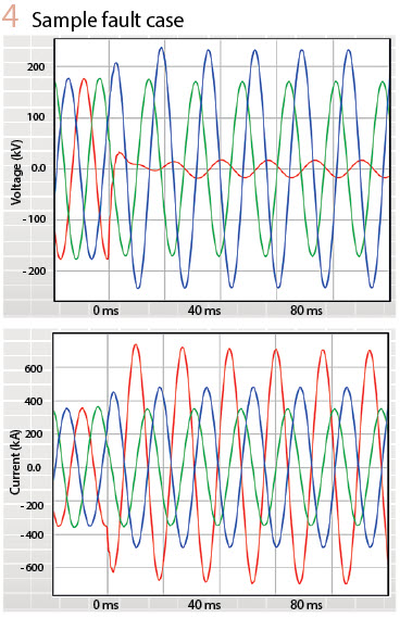
Figure 4 plots three-phase voltages and currents for an AG fault just outside the Zone 1 reach in a relatively weak system with CCVTs as voltage input sources. It also includes the plot of an instantaneous distance operating signal, IZ – V.
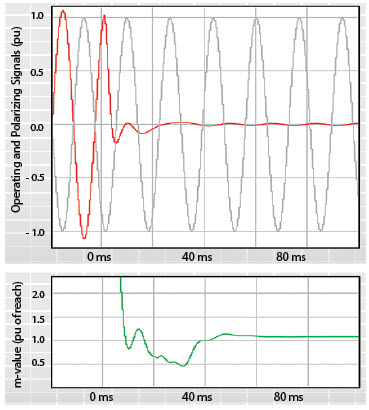
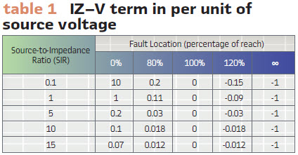
The plot also shows the polarizing signal to allow us to understand if the fault is internal (coincidence of polarities) or external (opposite polarities). We contrast it with the plot of the m-value, calculated using phasors. We clearly see that both the instantaneous IZ – V term and the m-value phasor term are temporarily fooled – this external fault appears to be internal until about 40 ms into the fault (CCVT-induced overreach). However, unlike the m-value, the instantaneous IZ – V term includes a wealth of information. We can use this information to restrain the distance element. Specifically, the IZ – V term is small, telling us the fault is close to the reach point or the system is weak or both (Table1); the IZ – V term is distorted with the CCVT transient and does not cross zero at expected times; the IZ – V term coincides with the polarizing signal for unequal periods of time during its positive and negative polarities.
Figure 4 illustrates the simple fact that when we compress information, we lose the fine features of what we observe. The m-value compresses information two-fold. First, it rejects the frequency spectrum, except the narrow band around the nominal frequency.
Second, it collapses a range of relationships between the voltage and current to a single number. Unlike the plot of the m-value, we clearly see a typical CCVT transient when looking at the IZ – V term.
Filtering
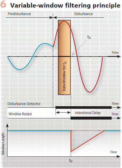
Is the half-cycle window better than the full-cycle window? How much filtering is optimum? Should a relay use multiple filters? Assuming a downstream protection logic (such as the coincidence timing in Figure 3) provides security, the answer is quite trivial: the filter window should exclude all pre-fault data and include all available fault data. At 2 ms into the fault, the window should be 2 ms long. It excludes the pre-fault data yet includes all available fault data. At 3 ms into the fault, the window should be 3 ms long and so on, up to a certain maximum length. This technique is known as a variable-window filter (Figure 6). Upon detecting disturbance, the algorithm reduces the window to a short length, such as 0.1 cycle.
The window expands with each new sample available, and after reaching a full size, such as 1 cycle, the window stops growing and starts sliding as in any traditional finite impulse response filter. The algorithm intentionally delays resizing, ensuring that transients associated with the pre-fault-to-fault transition do not pollute the initially short window. The logic may disallow resizing if the conditions are not proper, such as when clearing an external fault or before the relay has locked frequency. The 2020 Developments in Power System Protection (DPSP) paper, “A new digital filter using window resizing for protective relay applications,” describes such a variable-window filter in detail, including the group delay and off-nominal frequency compensation.
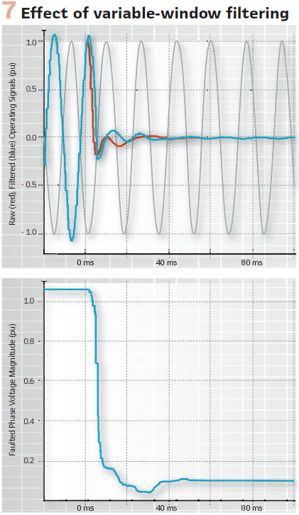
The variable-window filter is inherently a phasor estimator. It outputs two quadrature components of the input. Initially, the quadrature components have limited accuracy and are just the input signal and its derivative, but the accuracy increases as the window grows and the quadrature components become the real and imaginary parts of a phasor. Because the filter is compensated for the variable group delay, the real part of the output is the filtered input, while the complex output is a phasor representing the input. To illustrate this, Figure 7 plots the IZ – V term from Figure 4 as well as the magnitude of the faulted phase voltage, filtered using the variable-window filter. The benefits of this approach are clear. The relay sees the pre-fault-to-fault transition immediately after the window is resized, the initial errors are manageable (the downstream logic addresses these errors), the steady-state accuracy is excellent, and all these characteristics are achieved through a single filter outputting the best-known estimate of the input signal at the time.
Coincidence Timing in a Digital Relay
Figure 3 shows the basic principle of implementing a distance comparator, such as mho or reactance, through coincidence timing. A fast-sampling digital relay can follow this approach while adding a long list of enhancements and improvements, such as the following:
The coincidence timers can be integrating timers and integrate down or hold if their input temporarily deasserts. The integrate-down or hold behavior can be controlled dynamically based on other conditions, such as the level of the IZ – V term
Checking coincidence between the real and imaginary parts of the operating and polarizing signals can be done with separate timers or one integrating timer. The algorithm can switch between OR and AND logic when combining the real and imaginary parts based on other conditions, such as the level of the IZ – V term
The coincidence timer can assert its output after integrating 0.25 cycle in each half cycle or integrating a total of 0.5 cycle in each full cycle. The latter approach provides better ride through for transients. Again, the logic can switch between the two options based on other conditions
Coincidence timing can be suspended (hold or integrate down) if the raw and filtered IZ – V terms disagree in polarity or value
Coincidence timing can be suspended (hold or integrate down) if the relationship between the real and imaginary parts of the IZ – V term indicate the signal is still undergoing a heavy transient
The logic can reset the coincidence timers for selected events, such as fault inception or a switching event, allowing the measurement to start fresh for speed and security
Other similar solutions can be devised to optimize security and speed. Perfect dependability can be achieved by applying a short time delay to the phasor-based parallel calculations (torque, angle, m-values). Our message is that a digital relay can apply sophisticated calculations on samples or phasors and control the basic logic of Figure 3 in a way that is beyond the wildest dreams of analog relay designers. When run as a function in a digital relay, the analog-like scheme in Figure 3 does not drift, does not require periodic calibration, and does not fail the way static relays used to. This kind of implementation is the best of both worlds scheme – it marries advantages of the analog and digital implementations, while eliminating shortfalls of each. The 2020 DPSP paper, “A new digital distance element implementation using coincidence timing,” describes a sample implementation in more detail.
Test Results
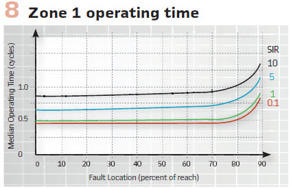
Designing a Zone 1 distance element is like running a 100-meter dash with a brick wall just past the finish line – you want to operate fast for in-zone faults, yet you’d better stop short of the remote terminal. Figure 8 shows the operating time plots for SIR ranging from 0.1 to 10 for our Zone 1 design implemented in hardware. The plots apply to magnetic voltage transformers or CCVTs that comply with Class 1 per IEC-60044-5. These operating times are measured at the relay terminals – between the change in the ac input current and the closure of the trip-rated output contact. The results speak for themselves: the combination of variable-window filtering and coincidence timing is a powerful tool for implementing distance elements.
Summary
The processing power of today’s relays allows them to digitally implement analog-like protection concepts, such as coincidence timing for distance elements. These concepts, developed at the peak of the static relay technology, are true but often forgotten gems. They have been discarded at the end of the static relay generation because they would not fit in early microprocessor-based relays. Instead, a new phasor-based path was started to make the digital relays feasible. Phasors facilitated a revolution in functionality, reliability, cost, and size. They served us well. The quest for a perfect phasor estimator that preceded and followed the first commercial digital relays was, however, misdirected (the vast majority of relays still use full-cycle Cosine or Fourier filters). Today, we have access to tremendous computing power in protective relays by combining fast multicore processors and field programmable gate arrays (FPGAs). We should no longer allow processing power to dictate how we implement protection. Instead, we can pick the best solutions from the past, improve on them, and continue innovating.
Biographies
Bogdan Kasztenny specializes in power system protection and control. In his decade-long academic career, Dr. Kasztenny taught power system and signal processing courses at several universities and conducted applied research for several relay manufacturers. Since joining the industry in 1999, Bogdan has designed, applied, and supported protection, control, and fault-locating products with their global installed base counted in thousands of installations. Bogdan is an IEEE Fellow, a Senior Fulbright Fellow, a Canadian representative of the CIGRE Study Committee B5, and a registered professional engineer in the province of Ontario. Bogdan has authored over 200 technical papers and holds over 50 patents.
Mangapathirao (Venkat) Mynam received his MSEE from the University of Idaho in 2003 and his BE in electrical and electronics engineering from Andhra University College of Engineering, India, in 2000. He is presently working as a principal research engineer at Schweitzer Engineering Laboratories. He was selected to participate in the U.S. National Academy of Engineering (NAE) 15th Annual U.S. Frontiers of Engineering Symposium. He is a senior member of IEEE and holds patents in the areas of power system protection, control, and fault locating.