By Philipp Stachel and Torsten Schumacher, Siemens AG, Germany, Yann Gosteli and Stefan von Glutz, CKW AG, Switzerland, Adolf Frei and Ramon Bächli, Hitachi Energy, Switzerland
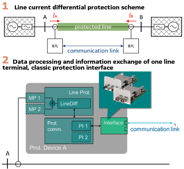
Line differential protection is a widely utilized and preferred method for protecting transmission lines across all voltage levels due to its inherent advantages. The scheme provides complete unit protection for the line without requiring time delay. This protection scheme only relies on current transformers (CTs) and is suitable for various types of network grounding, as well as short-line and multi-ended line applications.
Despite these benefits, line differential protection is encumbered by notable challenges. Reliable and fast communication channels must be established to enable the exchange of measured local currents among all line ends. Additionally, the reliance on vendor-specific protection communication protocols severely limits the possibility of multi-vendor integration. These proprietary systems are optimized for speed and low bandwidth while accommodating multi-ended applications. However, this uniformity necessitates that protection devices at all line ends originate from the same manufacturer – in some cases require even identical hardware and firmware versions. Device replacement can also become difficult when substations are located across organizational or property boundaries, complicating the planning and execution of upgrades.
This article discusses the traditional line differential protection schemes and contrasts them with novel approaches based on standardized international communication protocols. The objective is to eliminate the reliance on vendor-specific solutions, thereby providing interoperability, enhanced functionality, and user-friendly maintenance.
Classic Line Differential Protection
Commonly used line differential protection schemes operate by sampling measured currents at all line terminals and applying digital filtering methods to derive current phasors. These current phasors beside additional information are exchanged between all line ends via protection communication channels (Figure1). The physical media and interfaces of such channels might be similar for different relay vendors and may even be standardized (e.g. IEEE C37.94 or ITU-T G.70x E1/T1) – but the exchanged telegrams are proprietary. The telegrams contain proprietary data, optimized by the relay vendors for speed, low bandwidth requirements and multi-ended applications.
A typical example of such an internal processing structure of a protection device A is shown in Figure 2. The secondary currents of the CT are directly connected to the measuring point (MP 1) – for breaker-and-half installations also MP 2. This current (sum) will be processed by the line differential (87L) as part of the line protection. The internal signal processing will be different by the relay vendors. Typically, phasors are calculated using some kind of Fourier filtering. Other methods additionally calculate charge-proportional quantities.
A vendor specific protection communication interface (PI 1 + Interface) will exchange the processed quantities with all remote line ends. For such, serial direct point-to-point communication with star, chain or ring topologies are typically used. For multi-ended or redundant communication more than one communication channel is required (PI 2). Some manufacturers may deploy master-slave or master-master protection communication concepts, often requiring additional communication channels to link all line ends. The data received must be aligned with the locally processed currents. The most commonly used methods for such a phasor alignment are:
- Ping-Pong method
- This technique measures the round-trip time (RTT) under the assumption of symmetric channel delays in both directions.
- External synchronization methods
Alternatively, external signals such as 1 pulse per second (1 PPS), Global Navigation Satellite System (GNSS), or IEEE 1588 Precision Time Protocol (PTP) are applied to time-stamp the telegrams and account for asymmetric channel delays. Line differential processing is decentralized, with each line end managing its computational tasks independently. To achieve an equal behaviour of all relays in a protection scheme, the relays are aligned via intertrip signals. The benefits of such a vendor specific solution are the type tested performance, long-term experience and reliability under channel outage conditions.
An extension of such schemes often requires devices of the same type – some vendors even require the same firmware version. The access to all remote ends is necessary in case of testing the scheme or to do maintenance such as firmware updates. These limitations restrict the scalability and flexibility of classic line differential protection schemes.
Line Differential Protection based on Standardized communication
The constraints of classic methods underscore the need for standardized communication protocols that enable multi-vendor interoperability, mandate robust inter-substation time synchronization, and support remote tripping. Appropriate international standards, such as IEC 61588/PTP and IEC 61850-8-1 GOOSE, provide an ideal framework for modern protection schemes. Notably, GNSS-based synchronization shall be avoided due to vulnerabilities related to signal jamming or spoofing. Better approaches use redundant time sources (grandmaster clocks) and a time distribution throughout the communication network. Two potential international standards and approaches have been studied: exchange of sampled values or synchrophasor measurements.
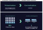
Exchange of Sampled Values (IEC 61850-9-2 SV): This method focuses on the exchange of raw current samples from (stand-alone) merging units (SAMU / MU) among line ends. Sampled Values (SV) necessitate higher bandwidth compared to traditional protection communication systems. Processing is centralized, allowing vendor-specific protection algorithms to be reused while accommodating raw data samples. This closely resembles busbar protection concepts but incorporates specific requirements for line differential protection, such as single-pole tripping, capacitive charging current compensation, in-zone transformers and auto-reclose functionalities. A beneficial side effect is that current waveform data from all line ends can be stored for disturbance recording, facilitating superior fault analysis. The system inherently supports new centralized protection methodologies built entirely on sampled values.
Exchange of Synchrophasor measurements (IEC/IEEE 60255-118-1): This approach calculates and transmits time-synchronized phasor measurements (voltages and/or currents), known as synchrophasors. Synchrophasors require a lower bandwidth, as they are derived from digital filtering processes; however, the filtering itself introduces delays that may affect system performance. Additionally, synchrophasors are applicable only for fundamental frequency components of the monitored signal, thus limiting their use in protection algorithms.
Additional Communication via IEC 61850 GOOSE: Binary information such as intertrip or CB status signals need to be exchanged between all line ends in both mentioned approaches. IEC 61850 GOOSE communication is well established for such applications and shall be applied in such centralized protection concepts. The process interaction (CB states, CB tripping) can be integrated in the MU or the remote interface unit. In all scenarios the interface between the local substation network and wide area network needs to be considered, and additional demands apply to the same. Clear demarcation points of local area networks from wide area networks with corresponding cyber security measures as well as protocol specific needs (e.g., IEC 61850 or IEEE 1588) have to be considered
Centralized Line Differential Protection: A Manufacturer Example
Due to the benefit of reuse existing and well proven protection algorithms, also based on methods in time-domain, we decided to follow the sampled values approach. The existing modular design of Siemens SIPROTEC 5 protection devices shall be reused as much as possible while implementing the centralized differential protection functionality explained herein.
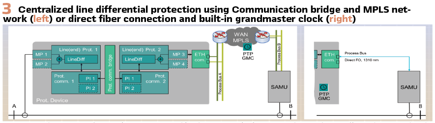
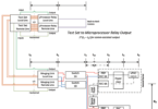
- Protection Communication Bridge: This method (Figure 3) emulates a physical protection communication channel using a virtual internal link. It simulates ideal communication with no delays, losses, or asymmetrical behaviours. Multiple instances of the communication bridge allow multi-ended line differential protection across up to six-line ends. Despite requiring higher CPU resources, results were consistent with existing 87L functionalities. An additional advantage here is the possibility to mix this approach with classical connected devices. This allows a smooth transition to the new technology and a step-by-step modernisation of existing substations.
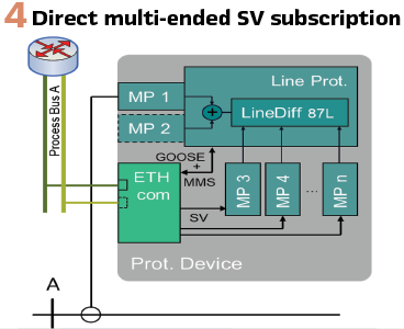
- Direct Multi-Ended Current Summation: Here, the direct subscription of SV streams from merging units at all remote line ends and local CT measurements are integrated similarly (Figure 4). This approach is more like to busbar protection schemes but necessitates substantial firmware modifications. Compared to the protection communication bridge, direct multi-ended signal processing is less resource intensive as only one 87L instance will be necessary.
Given the advantage of the reuse of a field proofed protection function and the flexibility for the introduction in the market, the communication bridge has been prioritized over direct multi-ended summation in case of Siemens devices.
Introduction of the Communication Bridge: The communication bridge forms the connection link of two instances of line (end) protections as shown in Figure 3.
The local currents can be measured using directly connected CT’s or using the process bus. The remote end currents are sampled using a merging unit (SAMU) and communicated using an inter-substation process bus. The local and remote end(s) must be synchronized. The PTP grandmaster clock can be situated in the communication network (Figure 3 left) or can be derived from the internal oscillator of the protection device (Figure 3 right). The latter simplifies the communication network to the remote SAMU. A simple fibre optic cable will be sufficient.
The practical length of such an application will depend on the optical budget of the channel and the used SFP in the ethernet communication module.
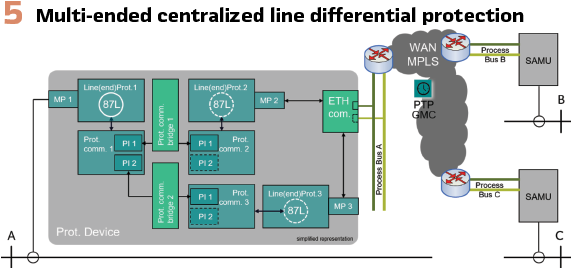
Multi-ended line differential applications: Centralized line protection with more than two terminals (e.g. tapped lines / renewable infeed) is possible when using multiple instances of line ends and protection communication bridges in one device. Practical limitations will exist for embedded protection devices and their limited processing power. For centralized protection systems based on industrial multi-core servers this will not be an issue. As described before, the direct summation of sampled value streams will be more computationally efficient. An example of such an approach is shown in Figure 5. Two remote ends are connected via an inter-substation process bus to the central protection device. A time synchronization of all line ends is mandatory. The device’s embedded system will be able to process up to three-line ends. Applications with more than three-line ends will require a mixed arrangement using also classical protection interfaces
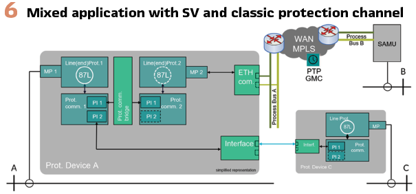
Mix of sampled values and classical protection interfaces: Figure 6 shows such a mix of line ends connected via the classical protection interface(s) and line ends connected via the inter-substation process bus. Such mixed applications will likely appear in brown field installations where existing two ended lines will require additional tapped line ends.
Such applications show the strength of the communication bridge as a reasonable approach to integrate new things into the existing processing structure. The overhead of multiple processing (87L instances) still needs some enhancements. Real field tests will show the actual market needs and will guide the developments.
Testing of Centralized Protection Schemes
The multi-vendor testing activities have been driven by CKW AG, a distribution system operator in Switzerland. CKW has applied the IEC 61850 standard for over 15 years and has implemented all interlocks with GOOSE ever since.
The original network concept has changed considerably since then and covers extensive measures for OT security. The biggest enhancements of the reference architecture compared to earlier versions is the segmentation of the station bus using VLAN, process and support networks were physically separated and additional functions such as RBAC were introduced on all devices or firewalls installed. The previously used ring structure was discarded in the latest concept. All protection and control devices relate to a direct connection. This means that each data flow can be monitored separately for its content and quantity. The approved data flow and the corresponding participants are recorded in the IDS and anomalies are reported. In the latest protection concept, CKW has determined that differential protection is used on all high-voltage lines. This acts parallel with distance protection and ensures an immediate shutdown of a fault-affected line.The CKW operational communication network (OT-WAN) is realized using MPLS-TP technology at 1 Gbit/s in the access area and 10 Gbit/s in the backbone. The entire communication network has time, phase and frequency synchronization and is operated with three different PTP sources. Individual paths are encrypted with keys from quantum random number generators using AES256. This algorithm can hardly be decrypted with the means available today and will continue to offer security even with the emerging availability of quantum computers. Differential protection data is transmitted on the MPLS-TP network via channel emulation and IEEE C37.94 and protection signal transmissions. These connections are switched redundantly. Failure of one connection does not lead to a service interruption (hitless redundancy). The connections between the gateways in the substations and the front ends in the SCADA are also transmitted with the IEC 60870-5-101/104 protocol.
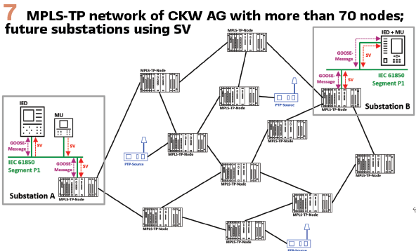
For future applications with process bus in accordance with IEC 61850-9-2, the OT-WAN serves as a PTP time source for all possible applications. This enables the transmission of SV streams within systems or across system boundaries. Future line distance protection is planned to be deployed using GOOSE messages between neighboring stations, including migration path with one side conventional and second end being GOOSE based
Laboratory Tests in 2023: Preliminary tests in collaboration with CKW AG, Siemens and Hitachi Energy in Switzerland took place in May 2023. Details about the MPLS-TP communication network of CKW AG and the engineering steps of both vendors can be found in paper no. 11112 of CIGRE 2024.
Figure 7 illustrates the MPLS-TP communication network of CKW AG with redundant PTP sources. Depending on the IED’s functionality, an SV stream of the line feeder can be provided on process bus for local protection and for the remote end line protection relay (Figure 7, Substation B). This function can also be separated, and a SAMU or MU may provide the SV stream for the local and remote protection devices (Figure 7, Substation A).
These tests focused on verifying interoperability, precise PTP-based time synchronization, and sampled values transmission over the real communication network using VLAN segregation. Different path delays were tested using different pre-defined signal routings. It was found that a total channel delay of approx. 2 ms is acceptable in these laboratory tests. Longer channel delays led to process bus buffer underrun and a blocking of the protection functions. This limit was achieved with a path routing of more than 250 km and more than 30 communication hops. For practical applications this seems more than sufficient.
Field Tests in 2025: Based on the promising results and ongoing firmware enhancements of both involved vendors, a field test was started in summer 2025. Test devices have been installed parallel to the operational equipment in two substations of CKW AG. Compared to the lab tests the device firmware now fully supports the centralized line differential protection as shown in this paper. Despite successful inter-substation sampled values exchange and robust time synchronization, minor engineering challenges with the GOOSE communication existed at the start of the field test. This was caused by an incorrect GOOSE dataset name. GOOSE supervision is a powerful device feature to detect such mismatches – but was disabled at the beginning. Such obstacles underscore the need for engineering tool enhancements to expedite interoperability among multi-vendor and inter-substation setups – for which the IEC 61850 was not intended by default.
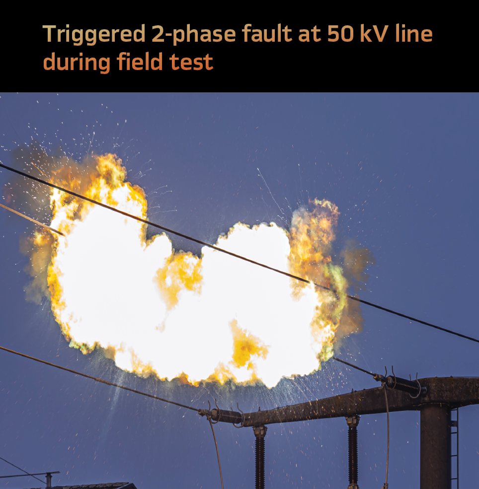
Due to no (internal) line faults occurred during the first months, an artificial fault was triggered in Dec 2025 using a drone with attached wire. This test was conducted at CKW’s high-voltage overhead line (50 kV) close to the substation Sursee. (see page 38).
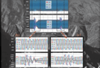
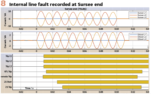
The short circuit was correctly detected at both ends. The first protection device detected the fault and issued a trip command as early as 7 ms after fault inception (Figure 8). At the remote end, the differential protection function registered the fault and initiated tripping after 12 ms. Both devices transmitted a GOOSE message to the opposite protection device. The communication transmitting time measured by the relays was 2 ms in each case and enabled immediate permissive tripping. Consequently, both protection devices would have triggered their trip contacts within 10 ms, i.e. in less than half a period. This represents a very fast operating time for a protection system.
The active distance protection REL 316 on Sursee end required 27 ms for fault detection and tripping decision. At the remote end, the tripping decision additionally depended on the information received from the opposite terminal via the permissive transfer trip, which added an additional 10 ms. The devices have been in use for over 20 years. The tipping time for instantaneous trips is usually between 15 ms to 30 ms.
A few days after the shortcircuit tests, additional trips occurred on the line under field test conditions. Freezing rain combined with strong winds led to ice-covered conductors of the overhead line. Falling ice caused short circuits on the monitored line as well as on the parallel line. All trip events were analysed in detail, and their operating times were compared. The results confirmed the findings obtained during the shortcircuit tests. All faults were detected immediately, and the disconnection would have been executed correctly and very efficiently. All trips would have been initiated within less than 10 ms. On the other hand: the protection scheme was stable for the few external faults observed.

- Summary and Outlook: The proposed centralized line differential protection approach leverages standardized IEC 61850 communication protocols, offering numerous advantages:
- Use of standardized protocols.
- Compatibility with diverse merging units across different manufacturers.
- Applications with Lines connecting substations owned by different companies across property boundaries can be easier maintained (no need of access to all ends even for testing or software updates)
- Multi-ended line protection using mix of classic and SV communication.
- Backup protection for remote line ends possible.
- Enhanced signal disturbance recording, with local currents from all line ends.
Future applications of such centralized line differential protection require a secure and fast inter-substation communication network. Centralized, redundant time sources (GMC) are key components for such wide-area applications. The transmission latency of the process buses will define the achievable length of the protected line. Real communication network burst tests shall be considered to measure the reliability of SV-based protection.
Biographies:
Philipp Stachel studied electrical engineering at the Technical University of Dresden, followed by a doctorate in power system protection. He was an application expert and R&D engineer, responsible for line protection topics. Since 2022, Philipp joined Siemens as a product lifecycle manager for line differential protection. His field of interest also includes communication systems and centralized protection and control. He takes on teaching responsibilities at TU Dresden and is member of IEC TC95, CIGRE SC B5.
Torsten Schumacher graduated in computer engineering at the Technical University of Berlin in 2005. He started working for Siemens AG in 2006 in Research & Development for Protection Applications. Today he works as a group leader for Protection Automation and Control as well as product owner for line- and transformer protection devices. He is senior key expert for the line differential protection function in SIPROTEC devices.
Yann Gosteli graduated with a degree in electrical engineering from the Lucerne University of Applied Sciences and Arts in 2005 and holds a Master of Advanced Studies (MAS) in Business Administration. He has been working on protection systems for high- and medium-voltage grids for 19 years. He is currently the Head of Secondary Systems at CKW AG and is responsible for the fundamental concepts of protection and control.
Stefan von Glutz graduated in electrical engineering from the University of Applied Sciences of Central Switzerland in 2006. He subsequently worked as a commissioning engineer for protection, control, and disturbance recording systems at ABB Switzerland Ltd. in Baden. In 2013, he joined CKW AG in Lucerne, where he is responsible for commissioning and maintenance of protection systems, fault analysis, protection concepts and settings calculations in the high- and medium-voltage power grid.
Adolf Frei holds a bachelor’s degree in electrical engineering from the University of Applied Sciences of Eastern Switzerland and an EMBA in Business Innovation from Kalaidos University. As Head of the Software Department for wired communication solutions for critical infrastructures, he focuses on distance and differential protection solutions using both conventional and IEC 61850-based architectures over packet-based optical communication systems, as well as the necessity of highly precise time distribution over the same infrastructure.
Ramon Bachli graduated from the University of Applied Sciences of Northwestern Switzerland in electrical engineering in 2002 and holds an EMBA in general management. He has extensive experience in the design of communication networks for power utilities. Presently he is working as a head of product management wired communications responsible for operational telecommunication solutions focusing on mission critical market segment. In this position he is also investigating in future technologies for mission critical operational communication networks.