by Mukesh Nagpal, Burns & McDonnell, Ajmal Saeed, Ricardo Rangel, and Daniel Zhang, Pacific Gas & Electric Company, and Ritwik Chowdhury, Schweitzer Engineering Laboratories, Inc. USA
Power system protection philosophies have historically been built around the predictable short-circuit current response of synchronous generators. During short-circuit faults, the current contribution of synchronous machines is governed by well-understood electromagnetic and electromechanical principles, producing high-magnitude fault currents with stable and deterministic relationships between voltage and current.
As power systems continue to transition toward higher penetrations of inverter-based generation, a clear understanding of cease mode behavior and its interaction with protection systems is crucial for maintaining system reliability, safety, and operational security.
Classification of IBRs
IBRs can be broadly classified based on their power-electronic interface and control strategy. Both characteristics play a critical role in shaping the magnitude, duration, and phase relationships of IBR fault current contributions, thereby directly impacting power system protection performance.
A. Partial Converter-Interfaced IBRs: Partial converter interfaces are used in Type III WTGs, which employ doubly fed induction generators (DFIGs). Figure 1 illustrates the simplified block diagram of this configuration. In a Type III WTG, the turbine drives the DFIG, whose stator windings are directly connected to the grid at the power-system frequency. The rotor windings are excited by an alternating-current (ac) source of variable magnitude and frequency through a partially rated power electronic converter.
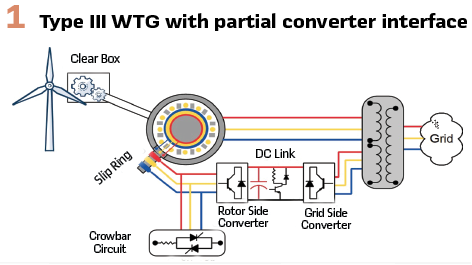
This arrangement enables the rotor to be supplied with a variable slip-frequency current, allowing for variable-speed operation over a range of wind conditions while limiting the power-electronic converter rating to a fraction of the machine’s total capacity. Because the stator remains directly coupled to the grid, partial converter–interfaced IBRs retain some characteristics of conventional rotating machines, particularly in their initial response following a disturbance.
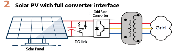
B. Full Converter-Interfaced IBRs: The PV systems, BESSs, and Type IV WTGs connect to the grid through fully rated power-electronic converters, commonly referred to as full converters or inverters. Figure 2 illustrates the basic configuration of a full converter–interfaced resource. In this topology, the converter decouples the energy source from the grid by converting dc, or variable-frequency ac, into a grid-synchronized, power-frequency ac voltage.
Because the converter processes the full output power of the resource, fully rated converters are generally more expensive and introduce higher losses compared to partial converter interfaces. However, they provide complete control over the magnitude, phase, and waveform of the output current, resulting in fault current characteristics that are almost entirely defined by control algorithms rather than by machine physics.
C. Grid-Following (GFL) Versus Grid-Forming (GFM) IBRs: Most IBR installations connected to transmission systems today employ grid-following (GFL) control. These resources utilize a phase-locked loop (PLL) to synchronize with the grid voltage and rely on an external voltage source to establish the system’s frequency and phase angle. As a result, grid-following IBRs are unable to operate independently following grid disconnection or during system-wide outages.
Early generations of grid-following renewable resources were primarily designed to inject balanced, positive-sequence current (I1) while maintaining active power output at prescribed set points. More recent grid codes and interconnection standards increasingly require the injection of negative-sequence current (I2) during unbalanced fault conditions, with the intent of approximating the fault response of synchronous generators. Despite separate requirements for I1 and I2 injection, the total phase current during a fault is typically limited to approximately 1.0–1.3 pu of the IBR’s rated current due to the thermal and electrical constraints of power-electronic converters.
Grid-following control strategies do not inherently address load–generation imbalances and therefore rely on external grid strength for stable operation. To mitigate these limitations, grid-forming (GFM) control strategies have been introduced. Drawing on long-standing experience from microgrids and islanded power systems, grid-forming controls enable converters to establish and regulate grid voltage and frequency autonomously, without reliance on an external voltage source.
At present, the deployment of grid-forming IBRs at transmission voltage levels remains limited. Consequently, disturbance events involving grid-forming resources are not included in the scope of this article.
Cease Mode, Ride-Through, and Reduced Short-Circuit Level
Most grid codes require IBRs to remain connected and successfully ride through voltage depressions caused by external short circuits and system disturbances. However, the events presented in this section demonstrate that specific IBR designs satisfy ride-through requirements by suspending active operation and blocking output current upon detection of voltage depression. This operational state, referred to herein as cease mode, can significantly reduce local short-circuit levels and adversely impact the performance of the protection system.
A. Extended Operation in Cease Mode-October 2018: This event illustrates a case in which a large IBR remained in cease mode for an extended duration, approximately 10 seconds, following a voltage depression caused by a phase-to-phase fault on the interconnecting transmission line. Prolonged operation in cease mode prevented local line protection from operating as intended, creating a risk of out-of-synchronism reclosing and compromising the facility’s safety.
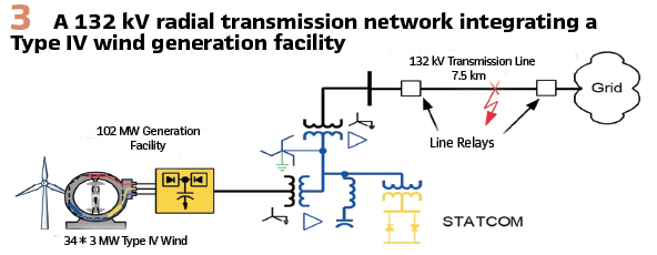
As shown in Figure 3, the event occurred on a short 132 kV radial transmission system that connects a 102 MW Type IV wind generation facility, consisting of 34 units rated at 3 MW each. A tree contact on the transmission line between the wind facility and a utility switching station initiated a Phase-C-to-A fault. Before the fault, the wind facility exported approximately 100 MW at a unity power factor. Figure 5 compares three-phase current waveforms recorded by line protection relays at both the utility and IBR terminals. The waveforms were preprocessed using a 60 Hz bandpass filter.
- Utility-side Response: The utility-side measurements exhibit a conventional synchronous generator–dominated system response, characterized by high-magnitude fault currents with equal and opposite currents in the two faulted phases and the distance protection operated correctly
- IBR-side Response: In contrast, measurements at the wind facility terminal show that the converter-based system rapidly reduced output current upon fault detection, collapsing to near-zero within approximately two cycles. This response deviates completely from the expected fault current contribution assumed by conventional protection elements. As a result, protection elements dependent on fault current magnitude and impedance measurement were effectively deprived of a usable input signal, rendering them unable to operate reliably
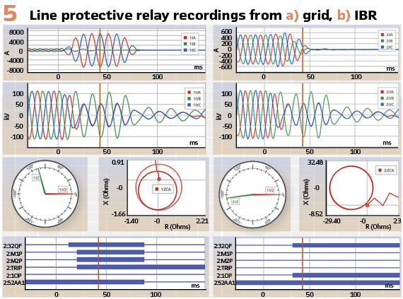
1) Protection System Failures on the IBR Side: Extended operation in cease mode caused multiple protection elements at the IBR terminal to fail or assert incorrectly, undermining overall protection dependability:
- The phase distance element at the IBR terminal did not operate. The apparent loop impedance trajectory deviated from the mho characteristic and expanded dynamically into the second quadrant, rather than the expected third quadrant
- Loss-of-potential (LOP) logic is asserted due to the combination of a substantial voltage drop and minimal change in current magnitude, further inhibiting distance element operation
- The directional element asserted forward (32QF) because the relay was configured to default towards the forward direction under LOP conditions to improve dependability
2) Risk of Out-of-Sync Closing: Based on additional event reports and sequence-of-events data (not shown), the wind facility remained in cease mode for approximately 10 seconds following fault initiation. Upon clearing the cease mode, the IBR attempted to re-energize the transmission line in grid-following mode. Since no valid grid voltage reference was present, this action resulted in voltage collapse at the facility’s terminal.
Simultaneously, the utility-side autorecloser, configured to initiate a reclose attempt after a 10-second deadline interval, initiated a reclose attempt. This sequence narrowly avoided an out-of-synchronism closing event, which could have resulted in severe damage to the IBR equipment.
Ultimately, time-delayed undervoltage backup protection operated to isolate the wind facility from the grid.
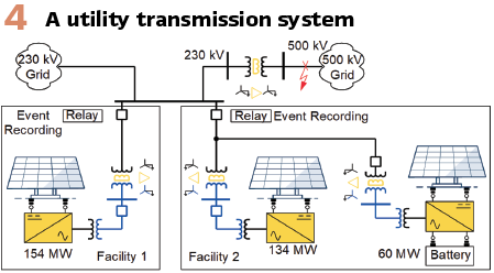
B. Inconsistent Operation in Cease Mode-August 2020: This event demonstrates that even when IBRs experience identical grid disturbances, their responses, particularly with respect to cease mode response, can vary significantly depending on inverter manufacturer and control implementation. The incident occurred on a transmission system involving interconnected 230 kV and 500 kV networks, as shown in Figure 4. Two IBR facilities were connected to the same 230 kV bus through separate interconnection lines:
- Facility 1: 154 MW solar PV plant
- Facility 2: 134 MW solar PV plant with an associated 60 MW BESS
Both facilities were equipped with smart inverters and were designed to comply with the same interconnection standards.
A Phase-B-to-ground fault occurred upstream on the 500 kV system. The fault was cleared by primary protection in approximately 50 ms. Figure 6 illustrates the markedly different post-fault current responses of the two facilities. Figure 6 (a) and 6(b) show the three-phase current measurements at Facilities 1 and 2, respectively, while Figure 6(c) and 6(d) show the corresponding three-phase voltages measured at the shared 230 kV bus. As expected, both facilities recorded essentially identical voltage waveforms during the event.
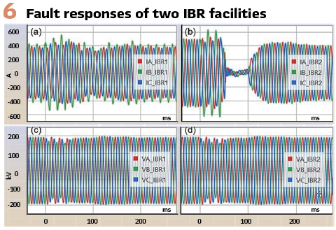
During the fault, the Phase-B voltage remained above approximately 85% of nominal at the IBR terminals. As a result, neither facility experienced a significant voltage depression, and both continued injecting currents close to their pre-fault levels during the fault. However, following fault clearance, the two facilities exhibited distinctly different dynamic responses:
- Facility 1 experienced only a minor reduction in current output between approximately 70 ms and 140 ms after which it quickly returned to injecting pre-fault current levels
- Facility 2 entered a momentary cessation state at approximately 50 ms, coincident with fault clearing, and remained in this state until roughly 100 ms. Although current injection resumed thereafter, the output remained below pre-fault levels for the remainder of the recording window (approximately 1.8 s; not shown)
This event revealed a response from Facility 2 that was inconsistent with the applicable grid code ride-through requirements and exposed inconsistencies in dynamic performance between the two IBR sites. Although both were designed to meet the exact interconnection requirements, their actual field responses differed due to variations in their implementations.
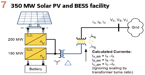
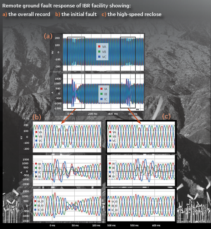
C. Camouflaged Cessation-April 2024: This event illustrates how the momentary cessation of current injection by IBR during a grid disturbance can be effectively masked by transformer zero-sequence current (I₀), potentially leading to an incorrect interpretation of the IBR short-circuit current response. In this case, the cessation was only revealed after the I₀ term was explicitly removed from the measured phase currents. The event occurred at a 350 MW solar PV and BESS facility interconnected to a 230 kV transmission system, as shown in Figure 7. A Phase-B-to-ground fault occurred on the transmission system and was cleared by primary protection in approximately two cycles.
Figure 8 presents captured oscillography, showing:
- Top panel: Three-phase bus voltages at the 230 kV IBR point of interconnection. The modest sag confirms the fault was remote
- Middle panel: Three-phase currents injected into the bus by the IBR facility during the event
- Bottom panel: The raw three-phase currents minus the raw I0
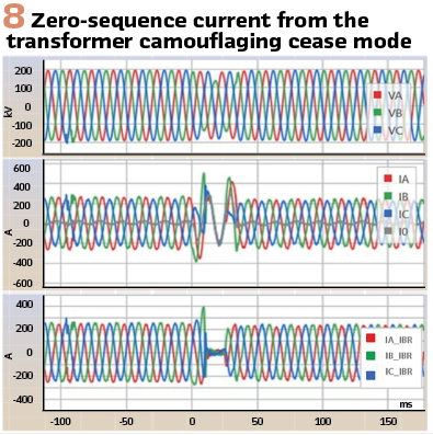
The facility was grounded through a transformer configuration that allowed zero-sequence current to flow during the fault. In the raw measurements, the relatively large apparent current indicated that the IBR remained online and injected reactive current to support the grid voltage. However, once the zero-sequence component was removed, the corrected waveforms revealed that the IBR had in fact entered momentary cessation for approximately one cycle, contributing negligible positive- and negative-sequence currents during that interval.
D. Partial Cease Mode or Reduced Fault Current: As discussed earlier, IBRs are intentionally designed to limit their short-circuit current contribution to approximately 1.0 to 1.3 pu of the rated current, to protect sensitive power-electronic components. Consequently, many grid disturbances do not result in complete current blocking but instead produce partial cessation or sustained reduced short-circuit current output level.
This subsection examines two disturbance events captured using deliberately sensitive triggering logic to provide enhanced visibility into IBR short-circuit current response during remote and near-remote faults.
1) Remote Phase-to-Ground Fault—June 2024: Figure 9 presents a one-line diagram of a radial 230 kV transmission line supplying three independent IBR facilities, consisting of solar PV, BESS, and shunt capacitor installations. The facilities are configured as follows:
- Facility 1: 250 MW solar PV
- Facility 2: 166 MW solar PV, 180 MW BESS, 28 MVAR shunt capacitors
- Facility 3: 274 MW solar PV, 300 MW BESS, 64 MVAR shunt capacitors
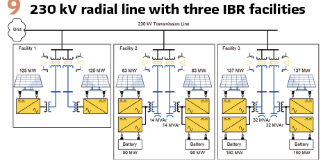
The aggregate installed capacity connected to the radial line is 1,170 MW, comprising 690 MW of solar PV, 480 MW of BESS, and a total of 92 MVAR of shunt capacitors. The full-load (1 pu) current of the 230 kV radial line is approximately 2,900 A. Sensitive undervoltage triggers were implemented at the grid-side breakers to capture system disturbances and analyze IBR dynamic response. This configuration proved effective, yielding multiple high-resolution relay records for external faults occurring on a remote 500 kV transmission line.
The Figure on page 38 shows the response of the aggregated IBR facilities to a permanent single-phase-to-ground fault located approximately 40 miles from the station on the 500 kV line. The fault was cleared by high-speed protection in approximately three cycles, followed by an automatic reclose after 500 ms. The phase currents shown in the Figure represent the sum of the contributions from all three IBR facilities, while the phase voltages are measured at the 230 kV bus. Zero-sequence current (I₀) has been removed from the phase currents and is shown in the bottom panel.
During the initial fault, the minimum phase voltage dropped to approximately 0.73 pu. The aggregated IBR current briefly increased from 680 A (0.23 pu) to 945 A (0.33 pu) for approximately half a cycle, after which the output current decreased to about 560 A (0.19 pu) before entering full cease mode for the remainder of the fault duration.
Following the autoreclose 0.5 seconds later, the maximum IBR current reached only 840 A (0.29 pu), with the facilities again operating in partial cease mode for the same fault location. Based on installed generation capacity and converter ratings, the short-circuit current contribution was expected to be approximately 1.3 pu. But the substantially lower observed currents confirm that the IBRs failed to deliver the anticipated fault current response, even under sustained fault conditions, from the perspective of transmission protection.
2) Close-in Phase-to-Ground Fault—February 2024: Figure 10 illustrates the response of the same IBR facilities shown in Figure 9 during a more severe phase-to-ground fault on the same 500 kV transmission line. In this case, the fault was located approximately one mile from the 500 kV/230 kV station. During this event, the Phase A voltage at the 230 kV bus dropped significantly to approximately 0.34 pu. Correspondingly, an increase in IBR output current was observed in Phases A and B, with a maximum magnitude of roughly 0.7 pu. The event occurred at approximately 6:30 a.m., when the solar PV facilities were not generating. All BESS units were online and assumed to have sufficient state of charge. Based on a rated continuous current of 1,200 A, the expected BESS short-circuit current contribution was approximately 1.3 pu (1,560 A).
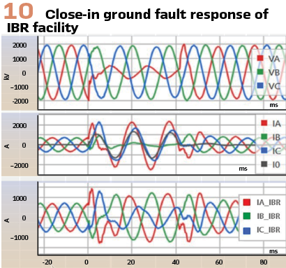
However, the measured current contribution was only about 860 A (0.7 pu).
This event further demonstrates the tendency of IBRs to enter partial cease mode or otherwise underperform during fault conditions, failing to deliver the expected short-circuit current contribution even during severe, close-in faults with significant voltage depression.
Conclusions: The cease mode implemented in many IBRs is intended to protect power-electronic converters by allowing the resource to ride through system voltage depressions caused by external disturbances without overstressing sensitive components. A critical drawback of this response, however, is that cease mode suppresses reactive power support precisely when it is most needed, during periods of depressed system voltage, thereby posing a risk to local and system-wide voltage stability. Furthermore, when operating in cease mode, an IBR may electrically resemble a disconnected source, potentially defeating dead-line supervision and increasing the risk of out-of-synchronism reclosing.

Recognizing these risks, modern grid codes and interconnection standards, including those aligned with NERC PRC-029-1 and IEEE Std 2800-2022, explicitly prohibit the use of cease mode during short circuit conditions, instead requiring IBRs to provide dynamic reactive current support during voltage depressions. In practice, however, the presence of zero-sequence current paths through transformer grounding can obscure the true dynamic response of IBRs. As demonstrated, removing the zero-sequence component (I0) from recorded fault current waveforms is often necessary to accurately assess whether an IBR complied with ride-through and reactive support requirements.
Biographies.

Mukesh Nagpal is a Senior Associate Technical Consultant at Burns & McDonnell and an IEEE Fellow. With over 35 years of experience in electric utility research and power system protection, Mukesh has made notable contributions to the economic, safe, and reliable integration of renewables into the electric grid. He has published approximately 50 technical papers.

Ajmal Saeed is a Principal Protection Engineer for Pacific Gas and Electric Company in Sacramento, CA. He earned his MSc in Electrical Engineering from Rensselaer Polytechnic Institute, NY and BS cfrom the University of Engineering and Technology, Lahore, Pakistan. His areas of interest include protection systems, electrical design, electric system modeling and engineering applications for the utility industry.

Ricardo Rangel has received his BSc from California State University, Fresno and MSs from University of California, Los Angeles. He is a registered Professional Engineer in California and works as a System Protection Engineer at Pacific Gas and Electric Company in Fresno, CA supporting the transmission system for 230 kV and below. His area of interest is power system impedance calculations using relay data and he has authored several technical papers on this topic.

Daniel Zhang is an Expert Protection Engineer with Pacific Gas and Electric (PG&E) based in San Ramon, CA. He supports PG&E’s 500 kV System Protection, Remedial Action Scheme, Phasor Measurement Units, etc. He received his BSc and MSc degrees in 1993 and 1996, respectively, from Xi’an Jiaotong University, Xi’an China, and MESc in 2003 from University of Western Ontario, London, Ontario, Canada. He has been working in the field of power system protection and control for over 20 years with utilities and engineering firms. He is a registered professional engineer in NY State.

Ritwik Chowdhury received his BSc degree in engineering from the University of British Columbia and his MSc degree in engineering from the University of Toronto. He joined Schweitzer Engineering Laboratories, Inc. (SEL) in 2012, where he is presently a principal engineer in research and development. Ritwik holds over 15 patents and has coauthored over 35 technical papers. He was recognized as an exceptional reviewer for IEEE Transactions on Power Delivery for three years. He is a past chair of the Protection and Control Practices Subcommittee (I-SC) of the IEEE Power System Relaying and Control (PSRC) Committee and the recipient of the 2021 PSRC Outstanding Young Engineer Award. Ritwik is a senior member of IEEE, a member of CIGRE, and a registered professional engineer in the province of Ontario.