Applying disturbance analysis and monitoring in IEC 61850 based digital substations
by Rene Midence and Anderson Oliveira, ERLPhase Power Technologies, Canada, and Nuwan Perera, Stantec, Canada
Smart grid technologies such as digital substations give utilities enhanced abilities to adapt to and create new opportunities from such change.
New digital substations and partial conversions of existing substations give utilities flexibility and can increase capacity, improve resiliency, speed repairs and expedite the design of system expansions or modifications to accommodate new resources. Other advances possible with a digital substation network include wide-area automation for rapid logic analysis and selectivity; fault location and service restoration (self-healing); load-shedding and islanding; and the automatic setting of relays. The technology is here, and new substation designs are transitioning to the digital world. New generation microprocessor-based Intelligent Electronic Devices (IEDs) provide flexibility, reliability, sensitivity, high speed, low-burden, a modular frame, small size, self-diagnosis, multi-function capability.
Utilities have migrated (or are planning to migrate) to digital based systems with new IEC 61850 based IEDs. Like the older technologies, new designs require solutions that not only expedite troubleshooting but also fulfill current and future requirements for local and wide-area integrated monitoring, recording, data management and system analysis.
IEC 61850 based implementations have made significant progress during the last few years. Major utilities around the world are at various stages of adopting and implementing the IEC 61850 standard. However, most of the focus has been on IEC 61850 Generic Object-Oriented Substation Events (GOOSE) messages and reporting using Manufacturing Message Specification (MMS). As utilities move towards completely digital substations (encompassing digitized currents and voltages, and switchgear statuses and control signals) for protection and control schemes, it is expected that the measurement infrastructure for fault and disturbance recording will change and be based on digitized IEC 61850 sampled values (SVs).
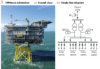
Digital substations require that analog signals from current and voltage instrument transformers (CTs and VTs) be digitized by merging units (MUs), and transmitted over the process bus using Ethernet communication. The process bus is an Ethernet network that links the primary equipment in a substation with various secondary equipment including protection, control, and monitoring equipment. In greenfield digital substations, large-size CTs and VTs can be replaced by non-conventional instrument transformers (NCITs) which directly convert the electrical signals into optical signals.
The IEC 61850 standard was initially released as a standard for ‘communication networks and systems in substations’ by the International Electrotechnical Commission TC 57 WG 10 in 2003. Part 9-2 of the IEC 61850 standard defines the service mapping required for the transmission of SVs. However, specific implementation requirements were not defined in the IEC 61850-9-2 standard. The IEC 61850-9-2LE implementation guideline was drafted by the UCA International Users Group to fill this gap by providing a guide that defines the logical devices, dataset and attributes, sampling rates, time synchronization requirements, and message format to be used by MUs in publishing SVs.
MUs typically sample analog measurements from current transformers (CTs) or voltage transformers (VTs), convert these analog quantities to digital signals, and then publish them over an Ethernet communication network as Layer 2 IEC 61850-9-2 multicast messages. Sampled values are transmitted using a publisher/subscriber multicast mechanism using two sampling rates. These are 80 and 256 samples per cycle (s/c), respectively. The former is specified for protection applications, while the latter is to be used for measurement-related applications.
Some of the benefits of an IEC 61850-9-2 system include: a decrease in project cost due to the reduction in copper cabling, better system-wide data availability/sharing, and reduced risk of CT saturation. Substation safety is also improved by eliminating concerns associated with open CTs (since electrical signals from the CTs and PTs are digitized).
Technical Considerations: Monitoring devices used in IEC 61850 based digital substations requires multiple features:
- Subscription to IEC 61850 SV and GOOSE data
- Perform mathematical calculations for PQ, harmonics, etc.
- Publish calculated data using IEC 61850
- Perform synchro-phasor calculations and publish the data for wide area monitoring
- Store the fault data and calculated data
- Support network redundancy
- Accurate time synchronization
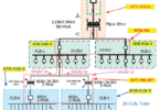
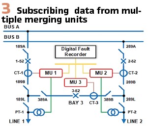
Subscribing IEC 61850 9-2 sampled value data from multiple merging units: IEC 61850 based substations include multiple merging units publishing data. Subscription of data from multiple merging units into a single monitoring device requires higher processing power and higher communication bandwidth. It is important to select a device capable of handling these challenges. (Figure 3).
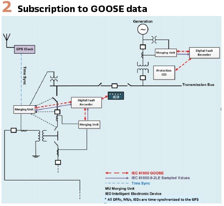
Subscribing to multiple IEC 61850 GOOSE messages
Substations include hundreds of status measurements that are monitored using GOOSE messages. The subscription of multiple IEC 61850 GOOSE messages into a single monitoring device (IED) requires a high level of processing. (Figure 2).
Publishing of IEC 61850 measurements suitable for wide area monitoring
IEC 61850 based wide area monitoring has become useful for digital substation applications. Publishing of IEC 61850 data/measurements requires utilization of IED resources such as processing power and communication bandwidth. In addition, a reasonable latency must be maintained between the publisher and subscriber. When selecting a monitoring device/IED, all these factors must be considered.
Monitoring large substations with multiple measurement inputs: The measurement requirement for larger substations can be as high as 200 (or more) current or voltage analog measurements and 500 (or more) status measurements.
The sampling rate for current and voltage measurements can be up to 256 s/c sample rate. The monitoring IED must be capable of handling these requirements without negatively impacting overall performance.
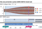
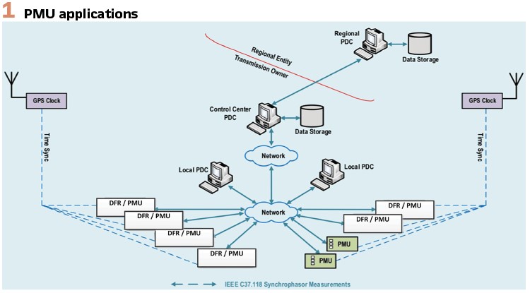
Synchrophasor calculations and streaming synchrophasor data: Standard IEC/IEEE synchrophasor calculations require implementation of P and M class filtering for multiple channels, involving significant computational power. In addition, reporting synchrophasor data as per the IEC/IEEE synchrophasor standard requires publishing calculated/measured data at higher reporting rates. In order to support synchrophasor calculations and streaming synchrophasor data, hardware must be selected carefully. (Figure 1).
Performing calculations: Multifunctional IEDs used for digital substation are required to monitor quantities that are not directly measured but that are calculated. A list of typical calculated quantities is summarized below:
- Summation channels
- Sequence calculations
- Power quality calculations
- Active power, reactive power and power factor calculations
- Harmonics and THD calculations
- Fault location estimates in transmission lines
- Power swing, voltage sag and voltage swells
All these calculations listed above are performed simultaneously and require digital filtering, discrete Fourier transform, vector transform, additions, subtractions, etc. An IED capable of handling all these functionalities requires a high degree of computational capacity. In addition, some of these calculations require buffering of historical data that demands extensive usage of memory.
In summary, technological challenges demand the following requirements for a monitoring device or IED:
- Adequate processing power to handle extensive calculations, filtering of data, etc.
- Adequate memory to buffer historical data
- Higher communication bandwidth to handle SV data
- Multiple communication paths to publish and subscribe data from multiple IEDs
- Capability to meet network redundancy requirements
- Capability to store large amounts of data or samples
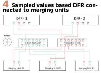
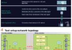
Application: In order to evaluate the operation of a sampled value based digital fault recorder, consider the following application shown in Figure 4. In this application, three industrial merging units with IEC 61850 9-2 LE support were considered.
MU Settings: Proper configuration of the merging units is an important step for a successful implementation. Important points to keep in mind are the sampling rate and the type of data that will be published by the merging unit, whether IEC 61869-9 or IEC 61850-9-2LE. In this case the merging units were configured to publish IEC 61850 9-2 LE data at 256 s/c rate. Other important configuration points to keep in mind during the configuration of the merging units are:
- The port number by which the merging unit will publish the data
- Application ID (APPID)
- Mulitcast MAC Address
- VLAN ID
- VLAN Prioirty
The subscribing IED needs to be configured for the number of Application Service Data Units (ASDU) the merging unit will publish, which is the data unit in which the measured values and other important information are contained. The measured values are saved in the field” Data Set.”
DFR Settings: The configuration process of a DFR in the digital environment is achieved in two steps:
- Sample value input mapping using IEC 61850 Configuration Tools
- Configuration corresponding to the use of the data to achieve the DFR functionality
In the sample value input mapping, with the use of an IEC 61850 Configuration Tool, the ICD or CID files of each merging unit are brought to the environment, and using the configuration tool, the DFR is configured to subscribe to the corresponding logical nodes containing the data published by the merging units.
The resulting configuration will place the data in the corresponding DFR memory locations. In this case, the DFR has up to 36 memory locations where data can be configured as either current or voltage.
Once the DFR is configured in the IEC 61850 environment for sample values, it needs to be configured to make use if the data.
Analog DFRs need to be configured based on the type of signal connected to each analog input. Through the internal analog to digital converter, the signals are digitized and utilized as configured.
In the digital environment, the so called “analog inputs” are no longer acquired via physical connections to the analog input terminals of the DFR. They are acquired through communications via the IEC 61850 process, therefore the DFR needs to be configured to recognize the sampled value input channels based on the memory locations configured with the IEC 61850 tool, which can be either voltages or currents.
Configuration of Summation Channels
DFRs have the ability to sum inputs, which is a very useful feature when monitoring an element of the substation in a ring bus or breaker-and-a-half configuration. This allow the DFR to monitor the individual currents and perform its functionality on their summed values. When the DFR collect records, the user will be able to see data from the individual currents and also their summed values. IEC 61850 sampled value inputs can be configured for summation calculations as well.
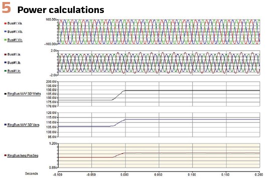
Power Calculations: Figure 5 shows an example of power quality calculations using IEC 61850 9-2 LE sampled value data captured during the prototype testing.
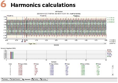
Harmonics: Figure 6 shows the harmonics calculations performed using IEC 61850 9-2 LE data captured by a DFR.
Voltage Sag and Swell: Voltage sags and swells are the most common types of power quality disturbances. Electrical equipment is designed and expected to work at a specific voltage rating that most not be exceeded for long periods of time. Changes in voltage below or above a low or high limit might damage the equipment and cause outages and other power quality issues.
A voltage sag is a brief reduction in RMS voltage of 10% or more below the recommended range for a period of 1/2 cycle to 1min as defined in the IEC 61000-4-30 standard.
Voltage sags are a common power quality event that can occur several times per year at a typical industrial site. It is required that electrical equipment has the ability to ride through brief voltage sag events. The requirement depends on the sag characteristics and the application. Voltage swells are the opposite of voltage sags and they are defined as a momentary increase in RMS voltage of 10% or more above equipment recommended voltage range for a period of 1/2 cycle to 1 min, as defined in the IEC 61000-4-30 standard.
Voltage swells are less common than voltage sags and they are usually related to system fault conditions. Swells may be caused by a single line to ground fault, with the consequent brief raise in the voltage level of the un-faulted phases. Swells can also occur when a large load is turned OFF.
Power quality monitoring is an important functionality of DFRs. They are capable of capturing data resulting from voltage sag and swell conditions.
To configure this function, it is important to know the expected voltage levels that will qualify to either a sag or a swell.
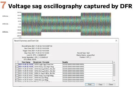
Figure 7 show a sample oscillography captured by the DFR during the voltage sag and swell conditions.
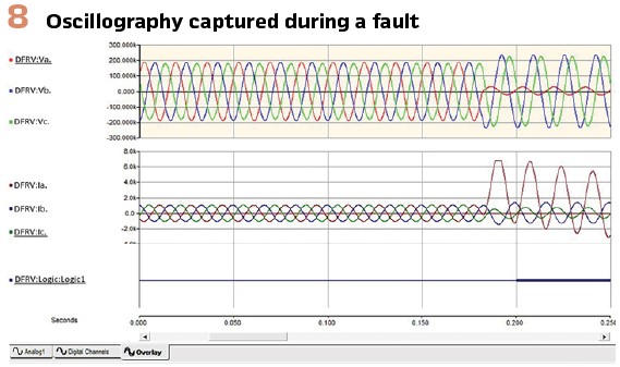
Fault Location Estimation: The DFRs are capable of calculating fault location on transmission lines during fault conditions. The Fault Locator Functions produce distance-to-fault information based on the impedance measured on the specified voltage and current channels of the respective line. The information is logged and available through SCADA protocols.
The following list shows the parameters that need to be configured in the DFR for this purpose:
- Initiating Event – this could be a single parameter for example when a current value is exceeded or a combination of parameters which can be configured by means of logic that will combine such parameters
- Current and Voltage analog quantities associated to the corresponding line for which fault location is desired
- Positive sequence impedance of the line
- Zero sequence impedance of the line
- Line length
When a user-configurable event occurs, the fault locator assesses the distance to fault using the user-supplied line parameters. If one or more of the impedances is consistent with a fault on the line, fault identification (e.g. B-G) and location information is generated in the form of an event message.
Figure 8 show oscillography captured during a single-phase fault. Table 1 shows the fault location estimation results.
Synchrophasor Application
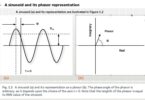
PMU capabilities are also offered by DFRs. Synchrophasors, phasor measurements with angles referenced to a global time standard, have been used in limited scope by electric power utilities for well over a decade for measuring and predicting dynamic stability of the power grid.
To transmit the PMU data reliably, time synchronization is a must, hence the need to connect the DFR to IRIG-B signal from a Global Positioning System (GPS) clock. The GPS signal must comply with the specification as mentioned in the IEEE C37.118 standard.
The PMU functionality is expected to comply standards for Synchrophasors for Power Systems as described below:
- IEEE C37.118 – 2005
- IEEE C37.118.1a – 2014 and IEEE/IEC 60255-118-1-2018 for P-class application
- IEEE C37.118.1a – 2014 and IEEE/IEC 60255-118-1-2018 for M-class application
- Other quantities that can also be transmitted in the PMU frame, in addition to the synchro-phasors are:
- Three-phase positive, negative or zero sequence phasors
- Summated phasors
- Analog quantities consisting of any combination of Watts, VARS, VA, DC, frequency and Total Harmonic Distortion (THD)
- Digital (status) quantities.
The successful implementation of Wide Area Protection and Control Schemes is based on the availability of, not only the synchro-phasors, but other measured quantities that can be key for decision making. For example, in an application for load shedding, having the status of the breakers and the power flow at any given time, allows the system to make best decisions to shade the appropriate load.
One more important point in a multifunction DFR that includes PMU, is the fact that all the features shall be able to function simultaneously with the existing features such as triggering, recording, continuous disturbance recording and trending.
The performance of a DFR that complies with IEC 61850-9-2 must not be affected and shall perform equally or better when compared to an analog DFR.
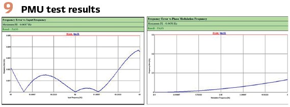
Figure 9 shows the results obtained during the dynamic testing of the PMU. It shows performance of the synchrophasor function using IEC 61850 sampled value data, as per synchrophasor test specifications.
GOOSE Input Monitoring: As expected in a fully digital environment, DFRs are expected to subscribe to single point status (Boolean), double point status, Health, Int32, or Int32u data types.
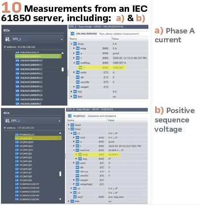
IEC 61850 Server Application: Measurements from the IEC 61850 server can be obtained using an IEC 61850 client such as IEDScout software. Figure 10 shows the Phase A current (Figure 10a) and positive sequence voltage (Figure 10b) from the measurement LD of the IEC 61850 server of the IED.
PTP – Time Synchronization: Most new digital substations are being designed with the latest technologies available, one of them is time synchronization by means PTP protocol, which is the preferred method in digital substations where time sync signals come via the communication network. IEDs used in such projects are expected to meet those requirements. DFRs are not the exception.
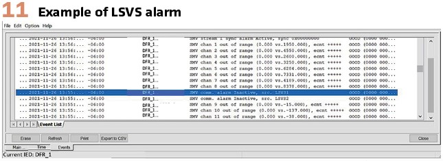
Monitoring of IEC 61850 Data Streams: Monitoring the health of the IEC 61850 GOOSE and SVM streams is important for troubleshooting purposes. The DFRs under evaluation support the LSVS and LGOS logical nodes. Figure 11 shows an example of LSVS alarm events observed during a failure in SVM data streams.
Simulation Mode: In IEC 61850 testing, the simulation operation mode enables testers to use a control command to put the IEDs into simulation mode. The DFRs under evaluation support simulation mode for GOOSE and SMV subscriptions. Simulation mode is set (on/off) for the entire IED. Conclusion: As more IEC 61850 based digital substations are implemented around the world, protection and disturbance recording functions are completely digitized and based on communication networks. Monitoring systems capable of providing complete visibility into digital substations are extremely useful. In this article, key requirements in selecting a suitable monitoring/recoding system have been discussed. The performance of such a fully digital recording and monitoring system was discussed using an example scenario simulated in a lab environment including typical functionalities such as PQ, fault location, and PMU.
Biographies:
Rene Midence (IEEE M’2007, IEEE SM’2009) has over 40 years of experience in power systems, protection & control, SCADA, substation automation and substation LAN systems. He has contributed to the development and successful introduction to market of new state-of-the-art protection and control microprocessor-based relays, and Ethernet switches and routers. He is a Senior Member of the IEEE with active participation in the development of IEEE Standards. He joined ERLPhase Power Technologies in 2010 and currently holds the position of Director of Technical Services. He graduated from the University of Honduras with a Bachelor of Applied Science degree in Electrical and Industrial Engineering.
Anderson Oliveira (IEEE M’2013) has over 18 years of experience in the power industry. He is registered as a Professional Engineer in the Province of Ontario, Canada, and hold both a Bachelor and Master of Engineering degree in Electrical Engineering.
He has worked for utilities, engineering consulting firms, and, currently, he works for a relay, power monitoring device manufacturer, performing engineering activities for generation, transmission and distribution systems on a domestic and multinational basis.
Nuwan Perera earned his BSc Electrical Engineering degree in 2003 from the University of Moratuwa, Sri Lanka and the M.Sc. and Ph.D. degrees from the University of Manitoba in 2007 and 2012, respectively. He is a senior IEEE member, actively involved with various IEEE Power Systems Relaying Committee (PSRC) working groups. He worked for ERLPhase Power Technologies from 2011 to 2021. Currently, he is working as a Project Engineer at Stantec Consulting, Winnipeg, Canada. He is also involved in academic research activities as an Adjunct Professor at the University of Manitoba.