By Alexander Apostolov, USA
As the electric power industry accelerates its transition toward IEC 61850-based digital substations, protection and control engineers are realizing unprecedented improvements in system functionality and efficiency. Yet, replacing traditional hardwired connections with Ethernet-based communications introduces a new set of complexities – particularly when it comes to capturing and analyzing transient events. Disturbance recording remains one of the most critical diagnostic functions in the modern grid, bringing significant benefits to post-fault analysis. However, operating in a fully digitized environment imposes unique architectural and network challenges that must be rigorously addressed during the engineering of the substation.
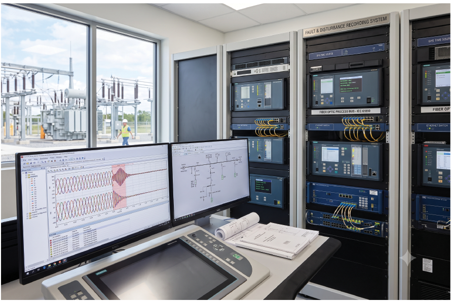
From managing network traffic loads to ensuring precise time synchronization across distributed logical nodes, understanding how to effectively architect these recording systems is no longer just an option—it is an engineering necessity.
Disturbance Recording System Components
A disturbance recording system in a digital substation has multiple components that perform different tasks and they are connected over the substation communications network according to the design principles implemented.
The first task that needs to be performed is the digitization of the primary current and voltage signals that need to be used to perform the disturbance recording functions.
In substations with traditional instrument transformers the digitization is performed using what is called standalone merging units (SMU) that are connected to the secondary of the current and voltage transformers. They produce a stream of sampled values based on the definitions of the IEC 61850 standard.
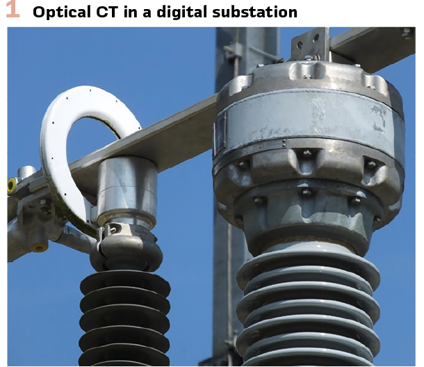
In the last couple of decades what is called low-power instrument transformers (LPIT) are being considered as the source of sampled values based on the conversion of the optical signal from an optical CT (Figure 1) or low level voltage signal from a Rogowski coil. The digitization is performed by specialized merging units that can be embedded with the sensor.
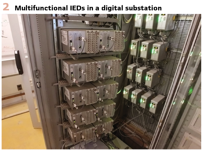
Once the analog signals are digitized the published sampled values can be directly used for transient recording by the subscribing devices or further processed to calculate the phasors or synchrophasors of the currents and voltages that can be used for the recording of wide area disturbances.
The triggering of the recording is typically done by a signal from a multifunctional protection IED that has operated during a short circuit fault condition. In the digital substation it is published as a GOOSE message that the disturbance recording element subscribes to (Figure 2).
To perform correct analysis of the different events that are being recorded by the system it is necessary that all components are accurately time synchronized based on the definitions of the precision time protocol (PTP) in the IEEE 1588 standard for time synchronization and its power utility profiles such as IEC 61850-9-3.
Communications are one of the key components of any digital substation based on the Ethernet protocol. Considering their importance, they have to be designed keeping in mind not only the requirements of the protection, automation and control system but also the impact of the disturbance recording functions on the traffic over the network, especially when extracting large disturbance record files.
These files are produced by the disturbance recording functions that may be located in different devices depending on their capabilities and the disturbance recording system architecture.
Disturbance Recording Modeling in IEC 61850
Based on IEC 61850-7-4 Edition 2.1, the disturbance recorder is modeled using a hierarchy of abstract and concrete logical nodes. The standard separates the recorder into three distinct functions:
- RDRE – the disturbance recorder function
- RADR – analog recording channel
- RBDR – binary recording channel
This separation is deliberate because it allows a recorder to support any number of analog and binary channels while maintaining a common recorder configuration and behavior. The model is based on the abstract logical nodes RecorderLN and DRChannelLN, which provide the common attributes inherited by the concrete logical nodes.
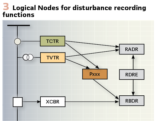
Figure 3 shows a simplified block diagram of the logical nodes used to model the different components of the waveform recording function.
The logical node class RADR is used to represent a single analog channel, while RBDR is used for the binary channels. Thus, the disturbance recording function is modeled as a logical device with as many instances of RADR and RBDR logical nodes as analog and binary channels are available. The sampled values from TCTR and TVTR are directly used as analog signals by the waveform recording function.
Any disturbance recording device has to be configured to perform this function. The available configuration parameters in a specific device are mapped to the mandatory or optional data objects in the different disturbance recording related logical nodes described above.
RDRE – Disturbance Recorder Function
RDRE is the logical node representing the disturbance recorder itself rather than an individual channel. It manages the recording process, recording memory, triggering logic, recording modes, and interaction with the individual analog and binary channels. Conceptually, RDRE acts as the controller of the recorder.
RDRE coordinates a collection of RADR and RBDR instances. It inherits all common recorder attributes from RecorderLN, such as operating mode, health, recorder blocking, trigger mode, pre- and post-trigger time and recorder statistics.
These common attributes appear in every recorder-related logical node.
Typical data objects include:
- Recorder status
- RcdMade – a record has been created
- RcdStr – recording is in progress
- FltNum – disturbance sequence number
- MemUsed – recorder memory utilization
These allow SCADA or engineering tools to determine whether a recording exists, whether recording is active, and how much recorder storage remains.
RDRE also exposes control objects such as trigger recording, clear recorder memory and reset recorder, allowing complete remote management over MMS. RDRE controls all recording RADR and RBDR channels.
RADR – Analog Disturbance Recorder Channel
RADR models one analog recording channel. Every measured analog quantity is represented by a separate RADR instance. For example:
- RADR1 IA RADR5 VA
- RADR2 IB RADR6 VB
- RADR3 IC RADR7 VC
- RADR4 IN RADR8 3V0
A recorder with 32 analog inputs therefore contains 32 RADR logical nodes.
RADR inherits all objects from DRChannelLN, including channel trigger status, channel number, source reference.
The channel number ChNum used in the recorder corresponds to the channel numbering used in COMTRADE which allows automatic generation of COMTRADE channel definitions.
The SrcRef in RADR references an existing IEC 61850 data object, for example:
- TCTR1.Amp
- MMXU1.A.phsA.cVal.mag
Thus, the recorder channel is simply linked to an existing measurement object which avoids duplication and guarantees semantic consistency.
RBDR – Binary Disturbance Recorder Channel
RBDR performs exactly the same function for binary signals. Each binary input has its own logical node.
Typical examples include breaker position, trip contact, protection operate, GOOSE received.
Like RADR, RBDR inherits from DRChannelLN.
Therefore, every binary channel has channel number, trigger status, source reference, trigger mode, pre- and post-trigger time.
The binary channel references IEC 61850 objects such as:
- XCBR1.Pos.stVal
- PTRC1.Tr.general
Use in Digital Substations
This object model is particularly powerful in IEC 61850-based digital substations because the recorder no longer depends on hardwired analog and binary inputs. Instead, each channel references an existing IEC 61850 data object through SrcRef, allowing recordings to include measurements from process-bus sampled values, calculated quantities, protection functions, and GOOSE-based events without duplicating data acquisition. As a result, a disturbance record can combine CT and VT measurements from TCTR and TVTR, calculated values from MMXU or RMXU, breaker positions from XCBR, protection operations from PTRC or PDIS, and even communication events such as GOOSE subscription status from LGOS.
The separation of RDRE, RADR, and RBDR therefore makes the IEC 61850 disturbance recorder highly modular, scalable, and semantically rich. RDRE manages when and how recording occurs, while RADR and RBDR define what is recorded. This architecture enables disturbance records to be self-describing and interoperable, with every recorded channel linked to a standardized IEC 61850 information model rather than to proprietary channel assignments.
Impact of the digital substation architecture on disturbance recording systems
The disturbance recording functions can be implemented at all levels of the substation protection automation and control system hierarchy. It can be in the process interface devices, in the different multifunctional IEDs or at the substation level. Regardless of where it is implemented within the digital substation it uses the same object modeling principles based on specific logical nodes defined in the IEC 61850-7-4 standard.
The digital substation architecture and the disturbance recording philosophy used have a significant impact on the traffic over the substation communications local area network. If the disturbance recording function is implemented within the individual multifunctional IEDs there is no traffic over the network until a specific record is required for the analysis of the performance of the PAC system for a specific event. The triggering of the recording is internal to the IED and does not require the publishing of any GOOSE messages for this purpose.
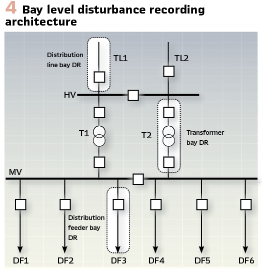
When the disturbance recording is implemented at the Bay level as shown in Figure 4, the traffic is limited only on the segments of the communications network that belong to the Bay that was involved in clearing of a fault or other substation event. The triggering of the recording is internal to the bay and requires the publishing of a GOOSE message from the IED that detected the fault for this purpose. The sampled values (SV) and synchrophasor (SP) communications between the process interface device (Figure 5) and the disturbance recording device are also limited to the network segment belonging to the Bay.
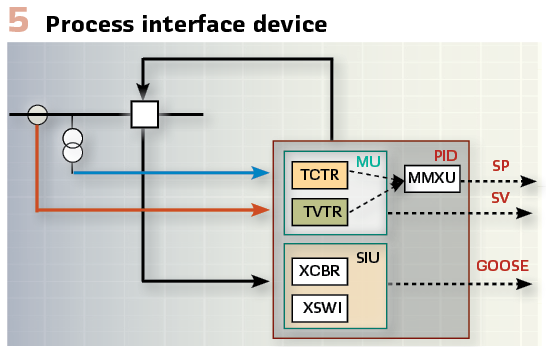
The PID contains two Logical Devices:
Merging Unit (MU) – it provides the current and voltage interface to the process based on the available interface options described earlier in the paper and publishing sampled values (SV) over the logical process bus to the disturbance recorder or any other substation function.
Switchgear Interface Unit (SIU) – it provides the GOOSE based interface with the circuit breakers and the disconnector switches as required by the different substation functions, including the disturbance recorder.
The PID may also include local protection or measurement functions, such as an MMXU. Since the PID is accurately synchronized, it will calculate M or P class synchrophasor measurements and will publish them over the substation LAN as defined in IEC 61850-90-5.
These measurements are used for disturbance recording.
The PIDs or Process Interface Units (PIUs) connected to primary equipment in the substation may also be used to communicate with a centralized disturbance recording system at the substation level. It can be a standalone device as shown in Figure 6, or an embedded disturbance recording function within the centralized substation protection, automation and control server.
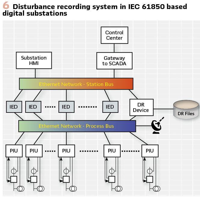
When the disturbance recording is implemented like this the traffic for both triggering and recording of short circuit faults or other electric power system disturbances uses all the segments of the substation communications network. The triggering of the recording is distributed and requires the publishing of a GOOSE message from the IED that detected the fault for this purpose.
Time Synchronization and Communication Architectures
Digital substations rely on robust communication protocols to ensure efficient operation and protection. Two key technologies that play a crucial role in this communication are Parallel Redundancy Protocol (PRP) and High-availability Seamless Redundancy (HSR) protocol. These protocols guarantee reliable data transmission even in the face of network failures, making them essential for disturbance recording systems.
The Parallel Redundancy Protocol (PRP) operates on the principle of redundancy. It duplicates all data packets and transmits them simultaneously over two independent communication paths. This creates a fault-tolerant network where a failure in one path wouldn’t interrupt the data flow.
The receiving device disregards duplicate packets, ensuring seamless data delivery. By eliminating single points of failure, PRP ensures uninterrupted data transfer during disturbances.
This is critical for capturing accurate pre-fault, fault, and post-fault data for analysis. Redundant paths also allow for faster detection of network issues. This minimizes the time it takes to initiate corrective actions, potentially reducing equipment damage and downtime.
PRP removes the need for complex redundancy mechanisms like Hot Standby Routers. This simplifies network design and reduces maintenance overhead.
High-availability Seamless Redundancy (HSR) takes a different approach to redundancy. It utilizes a dedicated, high-bandwidth ring network with two counter-rotating data streams. Data packets travel in a specific direction within the ring, with redundant copies circulating in the opposite direction. In case of a break in the ring, the redundant data stream seamlessly takes over, ensuring uninterrupted communication.
HSR supervision frames allowed a failed link to be localized, facilitating faster repair times. However, implementing a dedicated ring network and specialized HSR-compliant devices can be more expensive compared to PRP. Adding new nodes to an HSR ring can be complex and requires careful planning.
Both PRP and HSR significantly improve the reliability and performance of disturbance recording systems because reliable communications ensures capturing complete and accurate pre-fault, fault, and post-fault data for detailed analysis.
Digital substations rely on precise time synchronization to function effectively. Precise timing allows engineers to analyze the sequence of events during a power system fault. Synchronization ensures the measurements are time-stamped accurately, allowing for proper correlation and analysis of grid behavior.
Global Navigation Satellite System (GNSS) satellites provide a highly accurate time reference. Substation devices can receive GPS signals and synchronize their internal clocks accordingly.
Precision Time Protocol (PTP) is an industry standard that leverages existing Ethernet networks to distribute a synchronized time reference.
PTP offers microsecond-level accuracy, making it ideal for digital substations and disturbance recording applications
Impact of the transition to IEC 61869-9
Most of the digital substations that exist today around the world are used for the communications of the sampled values the IEC 61850-9-2 LE profile. However, the trend is that in the future it will be replaced by IEC 61869-9: Instrument Transformers – Part 9: Digital interface for instrument transformers developed by IEC TC 38 and published in 2016.
IEC 61869-9 is very similar to IEC 61850-9-2 LE and in order to support interoperability with the large base of existing digital substations devices that are implementing it, it can be configured to be backward compatible.
However, it is critical to remember that IEC 61850-9-2 LE specifies the sampling rates of the merging unit as a number of samples / cycle at nominal frequency while IEC 61869-9 specifies the sampling rate in Hz i.e. the number of samples per second regardless of the nominal frequency.
This allows the same merging unit to be used in a system with either 50 or 60 Hertz nominal frequency. However, the processing of the samples will be different in systems with different frequency because it will correspond to a different number of samples / cycle.
Another significant difference is in the number of ASDUs per APDU. While in IEC 61850-9-2 LE for protection applications we have 1 ASDU per message and 8 ASDUs per message for disturbance recording related applications. In the case of IEC 61869-9 for protection applications, we have 2 ASDUs per message and for disturbance recording applications with a sampling rate of 14400 Hz we have 6 ASDUs per message.
One benefit of this approach is that for both sampling rates we have the same number of messages per second – 2400 which will result in a significant reduction in the loading of the communications network since the number of messages used for sampled values will be cut in half.
Conclusions
The transition of the electric power industry from hardwired to digital substations brings significant benefits that improve the reliability, security and efficiency of its operations. The digitization of the analog signals based on sampled values communications defined in the IEC 61850 standard plays an important role in this and has an impact on the implementation of disturbance recording functions. It allows the disturbance r recording to be performed at each level of the substation protection, automation and control system hierarchy – starting from the process interface devices, and going to multifunctional IEDs, at the Bay or voltage level, as well as in centralized implementations.
The requirements for disturbance recording need to be taken into consideration during the design of the digital substations and the selection of the redundancy communications protocols such as PRP and HSR, as well as the time synchronization of all devices participating in the disturbance recording system implementation. The latest development in sampled values communications is the publication of IEC 61869-9 developed by IEC TC 38. IEC 61850-9-2 LE specifies the sampling rates of the merging unit as a number of samples / cycle at nominal frequency while IEC 61869-9 specifies the sampling rate in Hz i.e. the number of samples per second regardless of the nominal frequency.
This means that the same merging unit can be used in systems with different nominal frequency, however the disturbance recording systems need to process the received sampled values based on the system’s nominal frequency.
Biography:

Dr. Alexander Apostolov received his MS degree in Electrical Engineering, MS in Applied Mathematics and Ph.D. from the Technical University in Sofia, Bulgaria. He is Principal Engineer for OMICRON electronics in Los Angeles, CA. He is an IEEE Life Fellow and Member of the IEEE PSRC. He is past Chairman of the Relay Communications Subcommittee and serves on many IEEE PES WGs. He is a member of IEC TC57 WGs 10, 17 and 19, Convenor of CIGRE WG B5.86 and member of several other CIGRE B5 WGs. He is a Distinguished Member of CIGRE. He holds 5 patents and has authored and presented more than 650 technical papers. He is an IEEE Distinguished Lecturer. He is Member of the US National Academy of Engineering and Editor-in-Chief of PAC World Magazine.