by A. Melo, L. Ulrich, Schneider Electric, ES, U. Netto, U. Dreyer, Universidade Tecnologica Federal do Parana, Brazil, and F. Gonzalez-Longatt, Loughborough University, UK
Distribution energy systems (DES) have emerged as an exciting subject for investment and research in recent years. Consequently, a new set of technologies and approaches for better financial revenue, operation, supervision, protection, and maintenance have been applied; for example, the concept of wide-area protection generally used on transmission systems is now used on DES. DES has several directives regarding the operation, including personal safety and a high service continuity index. The protection systems’ performance influences both of them and is a concern during DES design and operation. Short-circuits, broken conductors and high impedance faults (HIF) are regular disturbances on DES. The last one represents a hazardous situation and a significant challenge to be correctly identified and extinguished. The research on this field is well documented.
Most of the techniques currently have been assessed experimentally only at the laboratory, but their performance on a real DES scenario is unknown. The primary interest is the feasibility, reliability, and cost of those techniques regarding a massive and practical application from the electricity utility companies’ perspective.
This article aims to evaluate trip time performance for a practical and cost-effective distributed HIF detection scheme based on modern auto reclosers’ features already installed in DES, such as the phase loss or source voltage loss protection function, embedded digital radio, and IEC 61850 standard. The authors achieved this goal by assembling a laboratory testbed comprising two commercial auto reclosers control, two digital radios, a relay test set, and the configuration and analysis software required.
Auto Reclosers Overview
In an overhead distribution system, most faults are single line to ground and present a temporary behavior. Although, the line-to-line fault and double line-to-ground could be temporary kind. Irrespective of the cause of the transient fault, when the protection system detects it and switches off the corresponding segment of the distribution system, after some time it is possible to attempt to return to the ordinary operation condition without interrupting customers’ supply.
Designing an approach to deal with transients faults will improve the continuity and service quality, underrating financial losses, an electric utility’s strategic goal. According to IEEE C37.100.5 – 2018, a recloser is a “self-controlled device for making, carrying, and automatically interrupting and reclosing an alternating-current circuit with a predetermined sequence of opening and reclosing followed by resetting, hold-closed, or lockout operation. It includes an assembly of control elements required to detect overcurrents and control the recloser operation.”
A recloser, is a vital component in power distribution systems, possesses several key characteristics that contribute to its significant role in maintaining a reliable electrical supply:
- Firstly, reclosers are designed to automatically detect faults in the power lines, swiftly interrupting the flow of electricity to safeguard against potential damage. These intelligent devices can discern between transient and permanent faults, allowing them to respond appropriately.
- Additionally, reclosers can initiate auto reclosing after a temporary fault has been resolved, promptly restoring the power supply to affected areas. However, in the case of a persistent fault, reclosers exhibit prudent behavior by refraining from reclosing until instructed to do so by an operator, preventing further complications. This state is known as recloser lockout and has a maximum limit of four protection trip operations. This behavior has been established as a standard by manufacturers
- Reclosers possess advanced fault-detection mechanisms, facilitating efficient maintenance and reducing downtime
Modern auto reclosers have introduced several new features that enhance their functionality and improve power system reliability. One notable advancement is incorporating advanced communication capabilities, enabling auto reclosers to integrate seamlessly into innovative grid systems. These communication features facilitate real-time monitoring, remote control, and data exchange, allowing for more efficient management and faster response to faults.
Another significant development in modern auto reclosers is the implementation of adaptive protection algorithms. These algorithms utilize advanced fault detection and classification techniques, improving the accuracy of fault identification and enabling more precise and selective reclosing. By accurately distinguishing between transient and permanent faults, auto reclosers can selectively restore power while minimizing unnecessary reclosing attempts, reducing system downtime, and preventing equipment damage.
Furthermore, modern auto reclosers often incorporate comprehensive fault-recording capabilities. These recorders capture detailed information about fault events, including voltage and current waveforms, fault locations, and sequence of operations. The availability of such data aids in post-event analysis, fault diagnosis, and system performance evaluation, enabling utilities to make informed decisions regarding maintenance and system upgrades.
Additionally, modern auto reclosers feature enhanced cybersecurity measures to protect against cyber threats and ensure the integrity of power system operations. These measures may include secure communication protocols, robust authentication mechanisms, and encryption techniques, safeguarding auto reclosers from unauthorized access and potential malicious attacks.
Some modern auto reclosers are designed with advanced self-diagnostic capabilities. These features continuously monitor the health and performance of the device, detecting internal faults or abnormalities. By proactively identifying potential issues, auto reclosers can alert operators or maintenance personnel, enabling timely preventive maintenance and minimizing unexpected failures. Overall, the new features found in modern auto reclosers contribute to improved fault detection, selective reclosing, remote control, data analysis, cybersecurity, and self-diagnosis, all of which enhance power system reliability, efficiency, and resilience.
Modern auto reclosers can be suitable for detecting broken conductors in distribution network systems. Some models also incorporate advanced fault detection capabilities that identify specific faults, including broken conductors. When a conductor breaks in a distribution network, it often results in an open circuit and a loss of electrical continuity. Modern auto reclosers can detect this interruption and respond accordingly.
These auto reclosers are equipped with sensors and monitoring systems to detect changes in electrical parameters such as voltage, current, or power factor. When a broken conductor is present, these parameters typically exhibit distinctive patterns or variations that the auto recloser can detect.
Upon detecting a broken conductor, the auto recloser can initiate appropriate actions, such as interrupting the power supply, logging the fault event, and alerting the utility operator or maintenance personnel. The auto recloser can also prevent unnecessary reclosing attempts, which could cause further damage or hazards. It is important to note that while modern auto reclosers can detect certain types of broken conductors, their capabilities may vary depending on the specific model and features of the device.
Detecting broken conductors may also rely on complementary technologies and systems within the distribution network, such as fault indicators or monitoring devices installed along the power lines. While auto reclosers primarily serve as protective devices and power restoration tools, they can contribute to the detection and identification of broken conductors in distribution network systems, thereby facilitating prompt fault identification and timely repairs.
IEC 61850 Generic Objected-Oriented System Event (GOOSE)
The IEC 61850 standards introduce different communication models and protocols. IEC 61850-8-1 specifically introduces the Generic Object-Oriented System Event (GOOSE) protocol. The GOOSE uses a publisher-subscriber model and is employed for fast and reliable system-wide data distribution. The fundamental working principle of a system employing GOOSE for application functions is as follows: Intelligent Electronic Devices (IED) configured as GOOSE publishers transmit GOOSE Ethernet packets (Layer 2) through a multicast association in the network. IEDs that are members of the multicast group receive these messages, and IEDs configured as GOOSE subscribers decode the received data and execute the necessary actions as expected by the application function.
Additionally, Layer 2 GOOSE does not utilize services from higher layers of the Open Systems Interconnection (OSI) model. This means that no IP or TCP services are used. Consequently, no handshake mechanism or data received confirmation is implemented, as these additional confirmations can impact transfer time performance. However, using GOOSE in critical application functions, such as protection schemes, requires mechanisms to prevent data loss and ensure reliability.
To ensure reliability without affecting the transfer time of applications, IEC 61850-8-1 introduces a retransmission mechanism for GOOSE messages. During steady-state operation, a GOOSE publisher continuously sends the GOOSE messages at a pre-configured frequency (Heartbeat). Once an event occurs that changes the value of an attribute member of the dataset, the publisher retransmits the same data, gradually increasing the time of transmission until it reaches the originally pre-configured steady-state time.
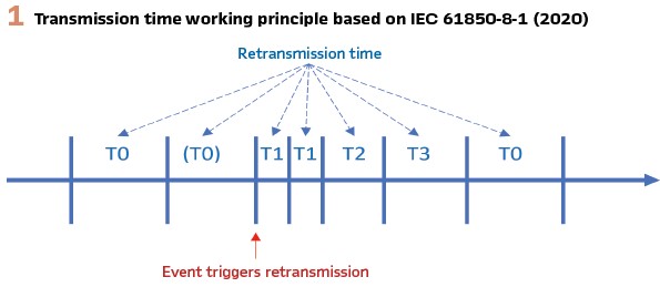
Figure 1 presents the representation of the retransmission mechanism specified in IEC 61850-8-1, where:
- T0 = Continuous transmission time in stable condition (Heartbeat). This parameter is fixed value configured at the Communication section of the system configuration language (SCL) file (MaxTime)
- (T0) = Continuous transmission time in stable condition may be shortened by an event
- T1 = shortest retransmission time after the event; This parameter is fixed value configured at the Communication section of the SCL file (MinTime)
- T2, T3 = retransmission times until achieving the stable conditions time; with MinTime ≤ T(n>1) ≤ MaxTime. The gradually increasing rate is a manufacturer issue, in the meaning that different IEDs can use different in-creasing rates
In addition, there are other mechanisms and parameters in a GOOSE packet that support the communication’s reliability.
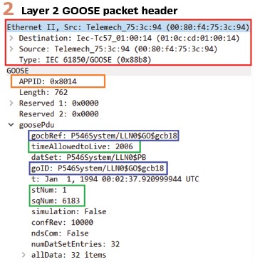
Figure 2 presents an Ethernet GOOSE packet captured with a network sniffer where some additional parameters to ensure the reliability of the communication are presented.
The Ethernet header in red presents the data used for the multicast association. The source unicast Media Access Controller (MAC) address is a fixed and natively MAC address of the IED publisher. The destination multicast address is a multicast group address where:
- The first bit transmitted shall be set to a value of 1 indicating multicast. The second bit transmitted shall be set to a value of zero indicating not broadcast
- The second and third octets have a value of 0C:CD (value assigned to TC57)
- The fourth octet should be 01 for GOOSE
- The last two octets should be used as individual addresses assigned to the multicast group (in the example 00:14)
The Ethertypes (Type) are registered by the IEEE authority registration. The presented the type 0x88B8 is Ethertype assigned to IEC 61850-8-1 GOOSE. The APPID presented in orange (0x8014), is used to select the frames containing GOOSE messages and to distinguish the application association. The value of APPID is the combination of the most significant bits of the Ethertype, and the actual ID. Consequently, the APPID reserved range for GOOSE is 0x8000 to 0xBFFF.
Moreover, some additional mechanisms and parameters are implemented to ensure the subscription reliability, as presented in green. The timeAllowedToLive parameter in the retransmission sequence guarantees the time before which the publisher publishes the next GOOSE message, while the subscriber uses this parameter to detect packet loss and determine the maximum waiting time for receiving subsequent messages. In addition, when an event triggers a retransmission. The StNum is incremented in one, and the SqNum is set to zero. This approach ensures reliable communication and helps maintain the integrity and synchronization of the system’s data.
Finally, due to the lack of reclosers supporting Routable GOOSE (R-GOOSE) in the market, it is important to notice that this section does not consider the R-GOOSE implementation in the statements.
Wide Area Voltage-Based Method
Several studies have been carried out to create a HIF detection method in alternative to substation-based systems. Studies show that Current-based methods can fail in more than 25% to detect HIFs. Voltage-based methods are often unnoticed since it is challenging to have enough voltage drop from the fault location to the relay upstream of the broken conductor. However, detecting the broken conductor as a system instead of as a single device measurement seems to be an attractive alternative. The reason is that the voltages’ behavior downstream of a downed and broken conductor is not considerably affected by the fault resistance.
There are different ways of detecting and handling HIFs, such as direct measurement of the electric quantities, energy and randomness algorithms, harmonic analysis, artificial intelligence, and mathematical morphology-based methods. This article presents a viable wide-area voltage-based method that uses the existent protection and telecommunication distribution system infrastructure.
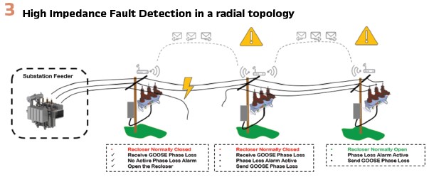
The proposed method uses the auto-reclosers loss of phase protection function and the IEC 61850-8-1 GOOSE protocol to detect and isolate the broken conductor circuit section, according to Figure 3. When the fault occurs, indicated by the yellow bolt on Figure 3, the recloser downstream of the broken conductor detects a phase loss (voltage dropped in one or two phases) or a source voltage loss (Voltage dropped in three phases) and sends the alarm by publishing a GOOSE message to the upstream recloser. The message is sent through the radio.
If the upstream recloser has no phase loss alarm activated, it opens the switchgear since it means there is a downstream broken conductor in its circuit section. In this case the fault will be isolated based on the voltage drop meaning as a broken conductor. In addition, other fault scenarios will activate the others recloser protections.
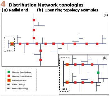
The proposed method is suitable for the most usual DES topologies, radial single and redundant, and open ring topologies. Figure 4 presents an example of radial and open ring topologies. For an open ring topology, SE 2 in Figure 4, the solution can cover the entire circuit up to the circuit’s connection (normally open recloser). In radial topologies, SE 1 on Figure 4, the method covers until the last recloser. However, the coverage can be extended until the end of the ramifications branch by adding reclosers or any other IEC 61850-8-1 complaint device capable of detecting a phase loss at the end of the circuit.
Methodology and Laboratory Tests
In this proposed HIF detection method, an Ethernet communication link between the reclosers is necessary to transmit the GOOSE messages; as the GOOSE message is an Ethernet multicast message, the correct segmentation is essential to avoid network overflow and latency issues.
Layer 2 digital radios are a widely used Ethernet media in distribution networks. These radios are also known as Ethernet radios, which means that their radio link works as an extension of its Ethernet bus physical layer. Thus, making possible the GOOSE traffic throughout the link. Other Ethernet media are used in distribution networks, for instance, some utilities use the fiber-optic infrastructure to connect the reclosers.
This work laboratory evaluation includes two different Ethernet media to compare their trip time performance. The first test is performed using copper cable to connect peer-to-peer the reclosers; and the second test is using a radio link to connect the devices. The TRIO radio used is a layer 2 radio with a license-free frequency range (902-928 MHz) and a 512-kbps bandwidth, reaching up to 140 km transmission length without a bridge/repeater.
This radio is also installed with Ethernet data compression and MAC address filtering technologies to avoid network-related issues. The auto-recloser should be complaint to IEC 61850-8-1, installed with the loss of phase protection. The authors had chosen the model ADVC3 Series to perform the tests, which is a commercial and suitable recloser for the application.
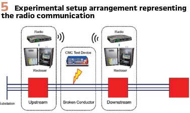
The laboratory test architecture (Figure 5) is composed of two ADVC3 connected via radio for the first test and connected directly with an Ethernet cable for the second test. A Hexa-phase CMC-356 test relay device was used to simulate the Loss of Phase, generating the secondary analog values and measuring the total operation time.
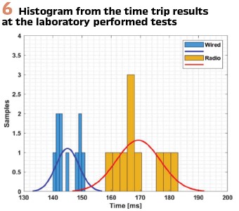
During the tests, the phase loss alarm was configured with the standard values to alarm when one or two voltage phases fall below 63 % percent of its nominal value for 0.1 seconds. When the signal is sent from the CMC-356 the recloser under alarm configured as broken conductor downstream sends a GOOSE message signaling the alarm to the recloser configured as upstream. Once the GOOSE alarmed is received, the recloser checks its phase loss alarm. Since there are no alarms, the recloser sends a trip order opening de circuit and stopping the test device injection. Figure 6 shows the histogram from 20 tests, 10 for each communication channel (wired and radio), performed and the trip time distribution results for each test.
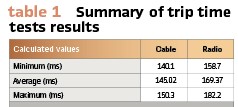
Table 1 shows the maximum, minimum, and average time using the radio link and the Ethernet directly connection obtained by analyzing the 20 tests repetitions.
According to the test results presented in Table 1, the proposed method can detect a broken or downed conductor in less than 200 ms. For a practical application, some considerations should be considered; the operating time can increase about 40 ms regarding the reclosers mechanism operating time.
The radio link latency can differ depending on the link quality, estimated by the radio link propagation study.
In circuits where it is possible to use optical links, the operational times could even decrease compared to radio and Ethernet connections.
Conclusion
This work presents preliminary results of a wide area voltage-based method to detect HIFs or broken conductors in DES. Since the proposed method considers the distribution network topology for the fault detection, a topology analysis is also required besides the loss of phase settings.
The usage of the IEC61850-8-1 GOOSE protocol makes possible the directly horizontal communication between the devices at the field level with no need for external intervention nor SCADA connections, which consequently reflects in speed and reliability on the fault isolation making it possible to detect the broken conductor in less than 500 ms, improving the overall operational security of the DES.
The detection method had a satisfactory performance on laboratory tests, suggesting being evaluated in a practical DES, even considering additional latencies, such as auto recloser’s arcing time. According to studies, a broken conductor takes around 1.4 seconds to hit the ground. With the author’s approach, it is possible to de-energize a broken conductor even before it touches the ground.
The IEC61850 standard is a fundamental building block of any modern Power system, and some reclosers like the ADVC3 are already inbuilt with the IEC61850 protocols. Consequently, it makes the presented method not strictly associated with only one device manufacture and cost-effective since there is no need for additional devices. The IEC61850 standards and the communication technologies advances make possible the implementation of the Wide Area Protection concept. This works also aims to exemplify how to handle one DES challenge by treating it as a system and not only as a single measurement node. The proposed method is not suitable in circuits with parallel sources, since it can limit the voltage drop at the downstream recloser.
The continuous work related to this research includes additional tests using a software model of a real circuit and the deployment on existing DES. Additionally, it can also apply the wide-area concept and GOOSE to improve the reclosers coordination and selectivity across the grid by interlock logics and protection.
Biographies:

Andre F. S. Melo is a Global System Architect at Digital Power Application Center (DPAC) of Schneider Electric. He received the B.E. degree in Computer Engineering from Universidade Potiguar (UnP) in 2017 and the M.S. degree in Electrical Engineering from Universidade Tecnológica Federal do Paraná (UTFPR) in 2021. He is now pursuing Ph.D. degree in Power Systems at Universidad de Sevilla. His fields of interest include Protection and Control System, Digital Substations, and IEC 61850. Mr. André is active member in various work groups of CIGRE B5 and IEEE PES PSRC and PSCCC.

Licyomar Hugo Ulrich is the Product Owner for Reclosers at Schneider Electric, working directly with the costumers on the development of new applications and features for distribution network protection and automation. Licyomar graduated in Electrical Engineer at UFPR – Brazil, in 2005, working at Schneider Electric since there, acting on several roles in power systems protection and automation.

Ulisses Chemin Netto received a B.Sc. degree in Electrical Engineering from Universidade Tecnológica Federal do Paraná (UTFPR), Brazil, in 2003. He received an M.Sc. and a Ph.D. in Power Systems from Sao Carlos Engineering School, University of Sao Paulo, Brazil, in 2008 and 2012. He was a postdoctoral fellow at LSEE/USP from 2013 to 2015. He is currently an assistant professor at UTFPR/PPGSE. His area of research interest is Power System Protection.


