by W. Caman, Luz del Sur, (Peru), I. Otarola (Peru), and J. Uzcategui (Venezuela), SOLTEC Soluciones Teleinformaticas y Control, D. Silva and A. Bittencourt, GE Grid Automation, Brazil
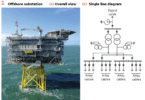
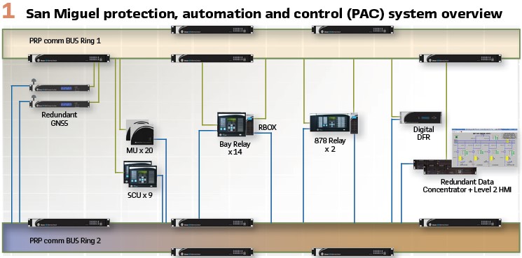
The SET San Miguel 220/60 kV digital substation is located in Peru, in the department of Lima, district of San Antonio de Chaclla. This substation was commissioned in December 2018 and was the second fully Digital Substation commissioned in Latin America according to the standard IEC61850-9-2LE (using GOOSE, SV and MMS messages as well as PTP synchronization through a process bus and a station bus) as part of the same project with Manchay Digital Substation, Latin America’s first Digital Substation commissioned in 2017. The architecture of the San Miguel digital substation consists of five bays of 220kV and four bays of 60kV, AIS type (Air-insulated Substation). The Manchay digital Substation have the same quantity of bays as San Miguel and an equivalent PAC system.

Description of San Miguel
San Miguel Substation is an AIS 220/60 kV type substation, double busbar at both voltage levels. It has five 220kV bays: two transmission lines, two power transformers TR2 (220/60 kV, 240MVA) and TR3 (220/22.9 kV, 50 MVA) and a coupler, and four 60 kV bays: two transmission lines, low voltage side of TR2 and a coupler.
The two transmission lines in 220 kV are connected to SET Carapongo and the two transmission lines in 60 kV are connected to SET Huachipa. At both ends of the lines, the PAC system is fully digital, GIS type (Gas-insulated Substation). The features of the PAC system are:
1) Fully digital and redundant architecture according to the standards IEC 61850-9-2LE, IEC61850-8-1, IEEE 1588 v2 PTP and IEC 62439-3 PRP
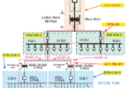
2) One unique redundant communication bus PRP shared by process bus and station bus separated by VLAN and multicast filters. It is composed of two 5-switch rings using 1 Gb/s interfaces. Each switch has 68 Gb/s of switching capacity
3) The VLANs in the communication bus are independent for each Service: Sampled Values, GOOSE, PTP, MMS and IEDs management, and using QoS (quality of service) and CoS (Class of service) functions. These services are differentiated with different priorities for the network traffic management according to the recommendations of the technical report IEC 61850-90-4.
4) For time synchronization application, the bus has two GNSS (Global Navigation Satellite system), each with GPS + GLONASS service and compliance with IEEE 1588 v2 PTP and IEC 62439-3 PRP standards
5) The Merging Units and SCU units are located near field devices (approximately 3 meters). They are in compliance with the standards IEC 61850-9-2LE, IEC 61850-8-1, IEEE 1588 v2 PTP and IEC 62439-3 PRP standards
6) The protection relays have PRP redundancy for the IEC 61850-8-1 GOOSE / MMS ports. The IEC 61850-9-2 LE ports are connected to the bus by RedBox PRP units. The protection relays have properties of Bay Controller and are used as Level 1 of operation
7) Digital Fault Recorder of 256 samples per cycle with IEC 61850-9-2 LE and IEC 61850-8-1 GOOSE standards, for recording measurements and events of Comtrade files when an event occurs in the substation electrical system
8) Redundant Data Concentrator with IEC 61850-8-1 Reports and IEC 62439-3 PRP standards for the integration of IEDs using the IEC 61850 standard. The Data Concentrator has embedded HMI and is used as Level 2 of operation
9) Remote management of all IEDs involved in the communication bus, including Merging Unit and SCU
10) The physical media used in the bus is fiber optic Multimode OM3 type, anti-rodent, anti-humidity and without conductive materials (see Figure 1).
Improvements Implemented
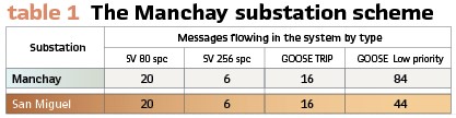
The number of messages that each IED publishes in the system was optimized. As both Manchay and San Miguel substations have the same number of Bays, the number of SV and GOOSE Trip messages were the same. The optimization was given for the case of low priority GOOSE messages, avoiding the repetition of signals in different GOOSE messages published by the IEDs. (Table 1).
The number of messages needed to be transmitted by the RSTP rings of the PRP system was optimized by reordering the physical connections in the network.
Part of the optimization of the messages in the system mentioned above allowed the optimization of the functional scheme of the busbar protection relay of 220 kV and 60 kV. The functional scheme of the 220 kV busbar protection relay is described for Manchay substation to explain the optimization.
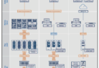
The 220 kV busbar (87B) protection relay of Manchay substation is configured to operate with the 220 kV bays as shown in Figure 2.
1) The busbar differential relay detects a fault in 220 kV busbars and publishes a GOOSE TRIP 87B message. The two main and redundant protection relays of each bay are subscribed to this GOOSE TRIP message
2) The protection relays of the bays in the Trip zone publish a GOOSE TRIP message. The two main and redundant Merging Units in the corresponding bay are subscribed to these GOOSE TRIP messages
3) The two Merging Units perform a physical trip on the two circuit breaker coils. The circuit breaker open confirmation message is a GOOSE low priority message published by the Merging Units and to which the busbar differential protection relay is subscribed
4) In case there is an activation of the function 50BF-S1 of the busbar differential relay, which is 150 ms after the 87B trip without receiving a circuit breaker open confirmation, the busbar differential relay publishes a GOOSE TRIP message again to retry the opening. The indications in (2) and (3) of this sequence are repeated
5) In case there is an activation of the function 50BF-S2 of the busbar differential relay, which is 250 ms after the 87B trip without receiving a circuit breaker open confirmation, the bus differential relay publishes a GOOSE TRIP message for external opening
6) The main and redundant protection relays of each bay are subscribed to this GOOSE TRIP message for external opening and send a DDT to the relay at the other end of the line in the case of line bays. In the case of transformer bays, they publish a GOOSE TRIP message subscribed by the Merging Units on the low side of the transformer
Description of Results
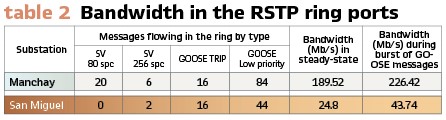
Table 2 shows the calculation of the bandwidth that consumes the RSTP ring ports of the communication switches. It has been considered that for a 60 Hz system, a SV of 80 spc (protection application) consumes a bandwidth of 5.76 Mb/s, a SV of 256 spc (measurement application) consumes a bandwidth of 12.37 Mb/s . A GOOSE Message consumes about 1 kb/s in steady-state and 1 Mb/s during bursts. The IEEE 1588 PTP protocol and MMS services are not considered in the calculation since they are the same in both substations and their consumption are not relevant for the calculation.
Since the ports used in the RSTP ring are of 1 Gb/s, for both substations Manchay and San Miguel the ports consume less than 25% of its capacity even in bursts condition.
However, there is an important optimization in the consumption of bandwidth in San Miguel substation, resulting in about 87% less in steady-state and 81% less during bursts compared with Manchay substation.
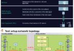
Testing the Communication Bus: The communication bus performance was tested with the scenario shown in Figure 3. During the test, it was verified the behavior of SV, GOOSE, PTP and MMS messages during different simulated failures in the proposed scenario.
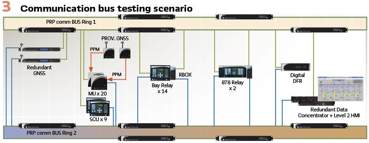
There were used two provisional GNSS, one of them generating one pulse per minute (PPM) in four Merging Unit of 220 kV and the other generating PPM in the eight Merging Unit of 60kV. So, during all the following testing described, there were in the system twelve bursts of GOOSE messages per minute.
Blackout test, turning off all the IEDs of the system and turning on again. The time of total recovery of the system was measured for both substations. It is considered that the system is totally recovered when there are no failure alarms of SV, GOOSE, PTP or MMS messages active in any IED of the system (GNSS, Switches, Merging Units, Protection relays or Data Concentrator). In both substations, it was obtained an average of about 8 minutes of total recovery (average after repeating three times the test)
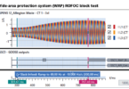
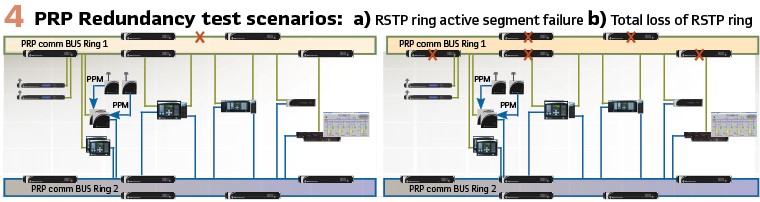
PRP redundancy test, simulating two possible failures on each RSTP ring of the communication bus as shown in Figure 4, an active segment failure of the RSTP ring and the total loss of the RSTP ring. In both substations there were no activations of failures alarms of SV, GOOSE, PTP or MMS messages in any IED of the system. That was the expected result since the recovery for a PRP system is 0 ms.
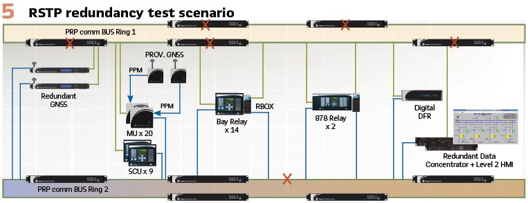
RSTP redundancy test, simulating a total loss of a ring followed by a failure of an active segment of the other ring, as shown in Figure 6. In San Miguel substation there were no activation of failures alarms of SV, GOOSE, PTP or MMS messages in any IED of the system. In Manchay substation there were activation of alarms of loss of SV messages in some Protection relays. It could be recorded by a packet analyzer that, in the worst case, SV messages were lost for about 70 ms (4.2 cycles of the 60 Hz waveform). Since the Protection Relays considers a bad quality message when more than 10% of points per cycle received are lost, there were a loss of 5 cycles of waveform in some protection relays in Manchay Substation. (Figure 5.)
Protection, Automation and Control Applications Response Time: The PAC applications were tested with the scenario shown in Figure 6. There were also used the two provisional GNSS generating the twelve bursts of GOOSE messages per minute.
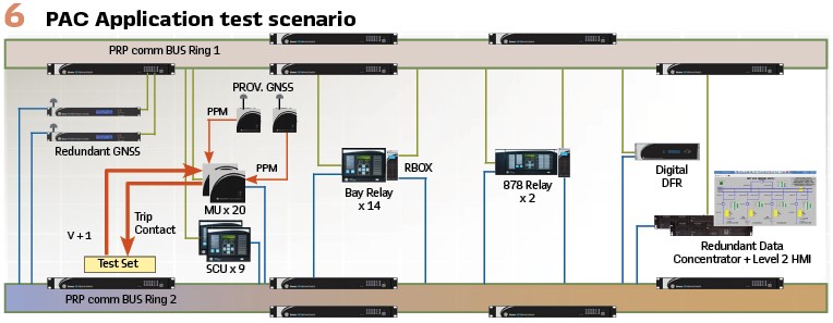
Protection Applications: The response time of the protection application was measured by injecting a fault secondary current directly to each Merging Unit and receiving the output trip contact from the same Merging Unit.
The expected total trip time is calculated as:
tTT = tSV + tRO + tPA + tGT + tMU
where:
tTT – Total Trip Time
tSV – Delay time of the Sampled Value message, 4 ms maximum
tRO – Operation time of the Protection Relay: 87L function <30 ms; 51 function <50 ms; 87T function <36 ms; 87B function <19 ms at 4.5 times the tripping threshold current
tPA – Time set on the Protection Relay according to the specific function
tGT – Delay time of the GOOSE Trip message published by the relay, 3 ms maximum
tMU – Operation Time of the MU output, 0.2 ms maximum
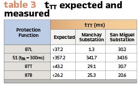
Table 3 shows some of the tTT measured in both substation for the different protection functions, taken from 220kV bays test and compared with the expected tTT calculated.
The results shown that the measured tTT for both substations are in the range expected for each function. For 87L, 51 and 87T function the times are almost equivalent (difference <2 ms) and in 87B function there is a difference of 4.7 ms.
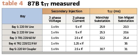
Table 4 shows the tTT obtained for the Busbar protection relay in both Substations Manchay and San Miguel. The results show an about 5 ms of trip time difference obtained by testing each bay at a time. This extra 5 ms in Manchay substation can be explained since in Manchay Substation there is an extra hop for the 87B function from the busbar protection relay to the bay protection relays.
So, it has to be considered an extra GOOSE Trip message delay and the operation time of the bay relay for the implemented logic of trip.
Automation and Control Applications: Both substations have four levels of Control. Tested was the the control from Level 2 (Local substation Data Concentrator HMI) and Level 3 (Luz del Sur Control Center) and measured the time between a command and a change of state received in the mentioned levels.
For both substations, a Circuit Breaker Open/Close command cycle takes about 250 ms in Level 2 and about 600 ms in Level 3, and for a Tap Raise/Lower command cycle takes about 3500 ms in Level 2 and about 4000 ms in Level 3.
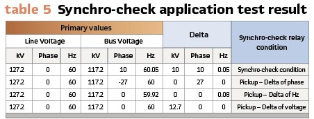
The scenario showed in Figure 7 was used to test the synchro-check application. A ramp was injected in the secondary side directly to the Merging Units and detected the delta at which the relay detects a synchro-check condition. Similar results were obtained in Manchay and San Miguel Substations. Table 5 shows the results obtained for this application in a 220 kV Line Bay of San Miguel.

The synchro-check application was set as Delta Line Voltage =12.72 kV, Delta Phase=30 and Delta Hz=0.1.
Busbar protection response (87B and 50BF): As described above, the functional scheme of the Busbar differential relay protection was optimized.
The optimization was not originally considered in San Miguel Substation, so it was used the same functional scheme of Manchay Substation. The purpose of using this functional scheme shown in Figure 2 was to avoid the subscription of all the Merging Units to the GOOSE TRIP 87B published by the busbar protection relay.
Since for 50BF-S2, all the protection relays of the bays are subscribed to the GOOSE TRIP 87B, it was used to transfer the 87B Trip throw the protection relays of the bays. As shown in Table 5, this functional scheme adds about 5 ms to the tTT for 87B Trip but it is still in the expected range of time.
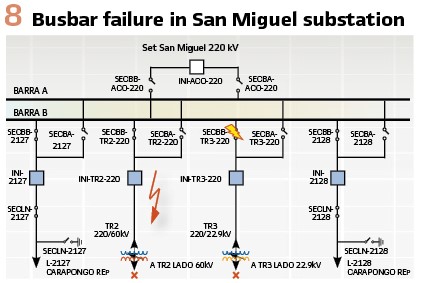
A busbar failure in San Miguel Substation tested on a real scenario the functionality of this scheme. An earth fault on the Bus B disconnector in the 220kV TR3 Bay when all the bays where connected to Bus B and the coupler disconnected originated a busbar differential Trip. (Figure 8).
The analysis of the event can be summarized as follows:
The failure is detected by the 87B relay and publishes the GOOSE 87B. Because of the bus B failure, the eight relays of the bays start protection functions, 21 Zone 2 the transmission lines and 50N the transformers. The eight relays publish a burst of GOOSE TRIP since the start signal was part of this GOOSE TRIP message.
All these eight high priority messages are being subscribed by the 87B relay
The eight relays of the bays publish a burst of GOOSE TRIP to be subscribed by the eight Merging Units to trip the Circuit breaker of their respective bay
The eight Merging Unit publish a burst GOOSE message with the change of position subscribed by the eight relays of the bays and the 87B relay
The clearance of the current failure is confirmed by the CB Open signal received in the eight relays of the bays 60 ms. after the order of trip
The signal of CB Open in the 87B relay is received after more than 250 ms, so the relay reaches to publish the GOOSE 87B to order the re-trip 50BF-S1 and also the external trip 50BF-S2
Because of the Trip 87B 50BF-S2, there are a CB Tripping on the other side of the transmission lines and on the Low voltage side of the transformers
Methodology of Testing
According to this experience, the methodology of testing for a fully digital substation should include among others, in order as mentioned:
1) Testing of the messages in the network, verifying the priority and content of the SV, GOOSE, PTP and MMS messages
2) Testing of the bus, including PRP/RSTP redundancy, bandwidth used on each port, VLANS and multicast filtering, behavior with Normal and High Traffic in the bus
3) Testing of GNSS redundancy (PTP synchronization redundancy) testing the GMC (Grand Master Clock) selection algorithm of the complete system
4) Testing of a general and partial Blackout of the system
5) Testing of behavior of the protection applications working in the complete system
6) Testing of behavior of Control and automation applications working in the complete system
7) Testing of the busbar differential protection considering a busbar failure similar as the one described in this article, to verify the behavior of the complete system during burst of GOOSE published by the majority of IEDs.
8) Testing of other specific application of the system that put all the system to work together as the case of the busbar differential protection
Biographies:

Willam Caman Munoz was born in Chachapoyas, Peru. He is an electronic engineer working in Luz del Sur, utility distribution of energy in Lima Peru. He has more than ten years of experience in the energy sector and is a project manager of PAC system projects in engineering and building of transmission substations department.

Ivan Otarola was born in Lima, Peru. He has an electrical engineering degree from the National University of Engineering, Peru. He has sixteen years of experience in Automation and SCADA system commissioning and eight years of experience in PAC system commissioning. He is currently the Manager of the Engineering and Service department in Soluciones Teleinformaticas y Control S.A. (SOLTEC), VAR of GE in Peru.

Julder Uzcategui was born in Barinas, Venezuela. He has an electronic engineering degree from the Experimental National University, Venezuela. He has twenty years of experience in PAC system commissioning. He is currently a Commissioning Engineer in the Engineering and Service department in Soluciones Teleinformaticas y Control S.A. (SOLTEC), VAR of GE in Peru.

Danilo Silva was born in Santa Catarina State, Brazil. He is currently Latin America Technical Support in GE Grid Solutions.

Annelise Bittencourt was born in Santa Catarina State, Brazil. She has an electrical engineering degree from the Federal University of Santa Catarina, brazil. She is currently a Lead Technical Application Engineer in GE Grid Solutions.