by Mark Adamiak, Adamiak Consulting, Herb Falk, Out of the Box Consulting Services, and Chuck DuBose, PCltek, USA
The IEC 61850 standard, from the beginning, defined a Device-to-multi-Device communication protocol known as the Generic Object-Oriented Substation Event or the GOOSE. The GOOSE was designed for event-based Intra-substation communication as it only had Layer 2 (Ethernet) addressing. As such, when a GOOSE message was received by a Router, the router would drop the message.
In the years since the original implementation, several Use Cases were identified where there was a need to be able to SECURELY route a message from one location in the grid to several other locations in the grid. These Use Cases prompted the implementation of Routable versions of both the GOOSE (event based) and Sample Values (periodic transmission of data). The original implementation of these profiles was defined in the IEC 61850-90-5 report (now deprecated). The latest release of the 61850 standard (Edition 2 – amendment 1) defines SECURE Routable versions of GOOSE (called Routable GOOSE or R-GOOSE) and of Sample Values (called Routable SV or R-SV) and addresses several deficiencies and errors in 90-5.
Message Security of communicated messages is more critical than ever before with several recent examples of hacks into control systems. Routable GOOSE and Sample Values define mechanisms to meet the security requirements of the industry.
This article will start with the identification of Use Cases for Transfer Trip, Remedial Action, and Synchrophasor Delivery. An overview of the solution in terms of the Routable GOOSE and SV will be presented as well at the functionality of a Key Distribution Center (KDC) and associated security architectures to meet NERC Critical Infrastructure Protection (CIP) requirements. Additionally, the performance of the system upon loss of communication to the KDC will be discussed.
Use Cases for New Communication Profiles
Communication profile development is typically started because of a need. The identification of the need and associated requirements is known as Use Case Development. Use Cases highlight the functional, security, message size, performance, number of devices, etc. required for a particular application. Several Use Cases that have highlighted the need for Routable Multicast Protocols are shown below.
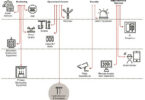
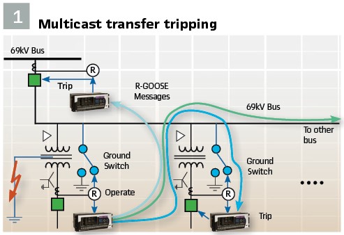
Transfer Trip to Eliminate Ground Switches: On certain distribution feeders with transformer taps, a fault in the transformer and associated lower voltage leads, cannot be “seen” at the head end of the distribution feeder (69kV bus in figure 1). A present solution is to install a Ground Switch on the higher-voltage line near the transformer tap that places a line-to-ground fault on the higher voltage line – which can then be seen at the higher-voltage primary breaker protection system. The ground switch solution shocks the system with a more “visible” fault – enabling the higher-voltage protection to see the higher-voltage fault. Shocking the system is not ideal and as fault currents increase with an expanding system, the levels of fault currents are starting to exceed available ground switch technology. An example of this is shown in Figure 1 where a fault in and around the distribution transformer which is detected by the 13kV protection. The transfer trip communication solution requires a Trip message be sent to all connected terminals. This function becomes a requirement for a Routable Multicast message. Figure 1 shows communication paths from the 13kV communication device to all associated breakers. This solution is significantly faster than a ground switch and less stressful to the grid.
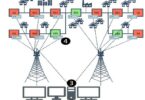
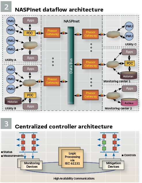
Periodic Multicast Messaging for Synchrophasors: As noted above, as Synchrophasors began to become a serious tool in operations centers, the need to be able to transmit Synchrophasors and Frequency information evolved. The North American SynchroPhasor Initiative (NASPI) developed a report identifying these requirements and developed a concept of how Synchronized measurement would need to be distributed in the future – shown in Figure 2. Of note, a need was identified for the Multicast of Synchrophasors from a source location to multiple Subscribers. It was noted that the messaging had to be periodic. As with GOOSE, security was front and center. One additional key requirement was the need to transfer large blocks of Synchrophasors from one operating center to multiple other operating centers.
Remedial Action Schemes: Remedial Action / System Integrity Protection Schemes/Systems (SIPS) are used to protect the integrity of the power system or strategic portions thereof from identified system failure conditions. A failure condition can present itself, as an example, as: Line 1 is overloaded; Line 2 is overloaded; and Line 3 just tripped out. A Remediation is then determined for the identified failure condition. SIPS are different from normal protection that protects localized faults in a power system protection scheme in as much as their operating domain can span the entire utility enterprise. Identification and remediation of System Integrity situations is typically accomplished through system dynamic studies which will include how to remediate any identified failure conditions. Performance requirements of a remediation scheme can be as fast as 50ms on an end-to-end basis.
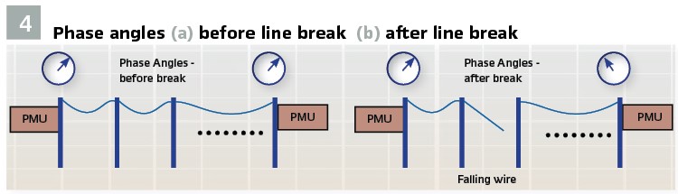
A centralized Remedial Action controller architecture is shown in Figure 3. In this architecture, monitoring devices measure various parameters of the state of the grid. This information is communicated to a Central Logic Processor that, upon examination of the state of the information gathered, determines if a pre-determined failure condition exists. If a system integrity condition is identified, Mitigation controls are securely issued to multiple terminals simultaneously.
In addition to the measured quantities identified above, Remedial Action schemes are starting to evolve to include Synchronized measurements from multiple locations on the grid to multiple Logic Processing systems (for redundancy). SIPS presents communication requirements for Routable Event messages as well as Routable Synchrophasors.
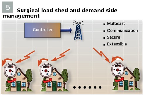
Broken Wire Detection: When a phase wire breaks on a line, the Voltages measured on either side of the break will show a step change in the synchronous angle (see Figures 4a and 4b). On a distribution feeder, measurements could be made at the different tap points on the line. A present solution communicates all Synchrophasor data back to the substation where the collected data is analyzed. An alternate solution is a distributed architecture where Synchrophasors are sent from one measurement point to all adjacent measurement points. The ability to communicate this data at sub-second intervals (30 messages per second) becomes a requirement in order to detect the change in angle and issue a Trip signal before the broken wire hits the ground.
Broken wires on transmission and sub-transmission lines can also be detected in a similar manner.
Surgical Load Shed / Demand Side Management: In most emergency actions, Load Shed is one of the primary lines of defense. In a load shed scenario, complete feeders or large facilities are tripped in order to reduce load. The most popular triggers of Load Shed are under-frequency and remedial action conditions. Operator action can also shed load when unstable operating conditions are detected. Often times, the outaged groups are rotated to minimize the disruption to society.
An alternative to complete load shed is the concept of Surgical Load Shed (Figure 5). In Surgical Load Shed, only non-essential loads are shed and essential loads are automatically rotated ON and OFF. Non-essential loads would include electric hot water heaters, electric clothes dryers, pool pumps, dishwashers, etc. Loads like electric heat and AC can be rotated OFF and ON. To implement such a control structure, a SECURE communication profile must be extensible to hundreds of thousands or even millions of meters / home controllers. It should be noted that most homes today have internet access and Load Shed/Control messaging, since it is secure, could take place over this link. Alternatively, radio has been demonstrated to be able to reach a 30 mi radius with Multicast messages. It should be noted that Demand Side Management messaging (i.e. – Variable Spot Pricing) can also be sent over this link.
Meeting the Requirements: Secure Routable GOOSE and SV
When GOOSE was first released in protective relays as a Layer 2 message (LAN only), it was realized that Device-to-Device communication had many applications – often times reaching outside the confines of the substation. One of the earliest examples of Layer 2 GOOSE applied over a wide area was in a remedial action scheme for load shed for events at the Palo Verde Nuclear plant. In this application, wide-area Layer 2 communications was established via a SONET channel that was configured to look like a Layer 2 network and could deliver a Layer 2 GOOSE message to any substation in Phoenix, AZ.
When the American Recovery and Reinvestment Act (ARRA) was passed in 2009, money was allocated for Synchrophasor projects in the US. At the time, IEC 61850 did not have implemenntations of a profile to provide Synchrophasor Delivery. To address this gap, work was tarted by vendors on development of Multicast versions of GOOSE and SV – now known as Routable GOOSE and Routable SV. The work defining the implementation of such was first codified in the IEC 90-5 report. As of February 2020, the information from the report (now deprecated) has been updated and included in IEC 61850 Ed. 2 – Amendment 1.
Secure Routable Multicast GOOSE/SV Overview
Multicast is the concept of sending a message from one device to many other devices. An example of Multicast is Internet Radio where one station can be live streamed to multiple subscribers. The above Use Cases indicate that Multicast IP is a requirement – that is – one message is shared with many network subscribers. The Publisher and associated Subscribers are defined as a Multicast Group and are linked by a Layer 3 and Ethernet Destination Address. By design, there is no limit as to the number of devices that can be part of a Multicast Group.

In the use-case analysis, it was noted that Synchrophasors are emitted on a periodic basis. The periodic emission was similar to that of Sample Values. As such, the Routable Sample Value profile is based on the 61850 Sample Value model of periodic data transmission. Similarly, it was noted that the multicast routing capability could be added to the GOOSE message with the obvious difference being that the Routable GOOSE or R-GOOSE is launched on Data Change or periodically and a keep-alive. The Routable message was created by adding a UDP-Multicast IP header to the message. To address the need for large Synchrophasor message transmission, the Payload was increased to 64,000+ bytes. The Use Cases identified that Security in the form of Authentication and (optional) Encryption was required. In the 2020 release of 61850, the security model – based on IEC 62351 – 9 for Layer 2 GOOSE and SV is defined. The Secure profiles for both the Layer 2 and Routable messages are shown in Figure 6.
Policy defines operational parameters of a Security Group. Policy is set by the KDC (per settings) and agreed-to by the members of the security group on items such as:
- What MAC algorithm is used to create the Hash
- What Encryption algorithm is to be used
- How often is a new Key is to be sent
- Is KDA enabled (defined below)
Session Header
Information about the Routable message is found in the Session Header and Policy. The same Session Header is used for both R-GOOSE and R-SV. Specifically, the Session Header identifies:
- Session Header
- # of bytes in the Session Header
- Header Length
- Session Number
- Version Number
- Security Information
- Time of current key
- Time until next key
- Key Identifier
- Initialization Vector
- Payload Information
- Message Authentication Code (Encrypted Hash)
Message Security
The security goals that were identified in the Use Cases are:
- Information authentication and message integrity (e.g. the ability to provide tamper detection) is required
- Confidentiality (via Encryption) is optional
Message Authentication is achieved through the calculation and inclusion of an Encrypted HASH signature that is computed using the data identified in figure 6. This signature is referred to as a Message Authentication Code or MAC and given that a Hash algorithm is used, the term Hashed Message Authentication Code or HMAC is sometimes used. A Hash – similar to a Cyclic Redundancy Check (CRC) is an amalgam of all the identified message bytes and encrypted with a Symmetric Key.
A Symmetric Key is a large number that is securely distributed to all members of a Security Group. The SAME Symmetric KEY is also used to Encrypt (if required) the message
(Note: only the Payload of the message is Encrypted). Upon receipt of a message, the subscriber re-computes the message Hash using the same algorithm and Key.
If the Received Hash is the same as the re-computed Hash, the message is declared to be Authenticated.
Key Distribution Center – KDC
As noted above, Implementation of security on R-GOOSE, R-SV, GOOSE, and SV requires that a symmetric Key be distributed to all members of a Security Group. The function or device that delivers the Symmetric key to the members is known as a Key Distribution Center or KDC. Membership in a Security Group is authenticated through validation of Digital Certificates held by Group Members and the KDC. The IEC 62351-9 standard specifies a protocol known as the Group Domain of Interpretation (GDOI – RFC 6407) as the key delivery / management protocol which makes use of X.509 Public Key Infrastructure (PKI) for Group Member validation. A PKI provides policies, and procedures needed to create, manage, distribute, use, store, and revoke Identity Digital Certificates.
There are several certificate distribution and revocation protocols available in the industry. IEC 62351-9 identifies, but is not limited to, the Simple Certificate Enrollment Protocol (SCEP) to deliver a PKI Identity Certificate and Online Certificate Status Protocol (OCSP) to revoke a Digital Certificate. As an example, in the case of an SV message, the Security Group includes the Publishing Merging Unit (MU) and all Subscribers to the MU’s dataset.
A Key is a large number – typically 16 to 32 bytes long (directed by policy) and is generated with cypher randomness. It should be noted that all security implementations are based on existing Internet standards and RFCs (albeit one was created to meet 61850 needs).
Symmetric Key Delivery can be performed by the KDC via two different mechanisms known as PUSH and PULL. In PULL mode, a Group Member PULLs or requests a Key from the KDC.
Before a Key is delivered, the KDC validates the Certificate of the requesting Group Member. On start-up, Group members must execute a PULL request to request keys in order to synchronize key usage or to address unsynchronized keys or when a PUSHed Key is not able to be decrypted or authenticated. When PUSH is set by Policy in the KDC, the KDC sends or Pushes of a Symmetric Key to the Group members.
The KDC is also responsible for the periodic re-keying (re-key time is user selectable) of all members of a security group as the longer a Key is in use, the higher the probability (albeit still small) of the key being cracked.
In the re-keying process, events on the grid may inhibit delivery of a new Key which, when the keys are changed, would render a Group Member unable to encode or decode a message. When security is implemented on functions such as Transfer Trip and Remedial Action, it is critical that failure to deliver a new key does NOT inhibit operation of the function. To address this scenario, a policy known Key Delivery Assurance (KDA – specified in IEC 62351-9)) can be utilized. With KDA enabled, the KDC in Push mode can ascertain if a Key delivery attempt to a Group Member is successful. If Key delivery is successful to a user-specified percentage of the Group members, a KDA message is sent to the publisher of the group which allows the publisher to change keys at the specified time.
IEC 62351-9 enhances GDOI so that two keys are delivered simultaneously (the current and next key) and the policy of when the next key becomes active. This is provided to all group members and the typical rotational period is twenty-four hours. Therefore, there are enough keys delivered to allow key rotation (e.g. between the two keys) for forty-eight (48) hours.
The KDC function should be extensible to meet the needs of most any size domain of management including, but not limited to: enterprise communications, control centers, substations, generation facilities, distributed energy resources (DER), distribution networks, and home meter communications.
Conclusion
The next generation Power System will rely heavily on secure communications – spanning the entire power system enterprise. IEC 61850 now provides multiple SECURE communication profiles to meet the system communication needs today and into the future.
Biographies:

Mark Adamiak is an independent consultant for the electric power industry. Mark started his career in the utility business with American Electric Power (AEP) and in mid-career, joined General Electric where his activities have ranged from advanced development, product planning, application engineering, and system integration in the Protection and Control industry. Mr. Adamiak is an original member of the IEC61850 WG, a Life Fellow of the IEEE, a registered Professional Engineer in the State of Ohio and a GE Edison award winner. Mark was the Principal Investigator for the EPRI IntelliGrid project to develop a reference architecture for the Smart Grid. In 2012, Mr. Adamiak was elected to the US National Academy of Engineering

Herbert Falk is the Vice President of Testing for the UCA International User Group (UCAIug) and is responsible for managing the Conformance and Interoperability Test Programs within UCAIug. He has managed IEC 61850 Interoperability Tests bi-annually since 2011. He is an editor of IEC 61850 and the US Technical Advisory Group (TAG) lead on Cyber Security to IEC TC57 WG15. He is an active member of the IEEE Power Systems Communication Committee (PSCC), IEEE Power System Relaying Committee (PSRC), and the DNP Security Task Force. Herb graduated with MSEE degree from Northwestern University in 1979.

Chuck DuBose has 40 years of power system experience with extensive knowledge in transmission operations, power system models, and software. This experience includes multiple EMS databases, the IEC Common Information Model, relay protection, and distribution engineering techniques. At Dominion Energy, he was responsible for the EMS transmission model and supporting the Transmission Operations Center with network applications analysis.
Mr. DuBose is Convener of the IEC TC 57 Working Groups 13 and 14, responsible for maintaining the Common Information Model (CIM). He lends his expertise in power system modeling and his operations experience to influence decisions concerning changes to the CIM definition. He participated in the EPRI-sponsored “CIM for Planning” and “CIM for Dynamics” projects. He has taught multiple courses on CIM.