by Alexandr Stinskiy, Suraj Chanda, Siemens, USA
The increased penetration of distributed energy resources requires new protection and control algorithms to maintain stability and reliability of the distribution grid. These algorithms heavily rely on live data from the field devices to make fast operational decisions during the fault events.
When a line fault occurs, the protection scheme is expected to interrupt the fault current and quickly disconnect other power sources to protect the Distributed Generation (DG) site from any damages, ensuring that it will not feed into a faulted circuit while line repairs are made by field crews.
This is achieved via Direct Transfer Trip (DTT) signals, traditionally sent between substations and remote DG sites using leased telephone lines. Due to the highly specialized and critical nature of DTT systems, the equipment, including the communication infrastructure, must be extremely reliable and conform to highest substation standards. The use of traditional leased lines is becoming more and more problematic as telecommunication companies are moving away from this technology or even not providing this as a service. Fiber utilization is not always feasible due to the installation cost for long distances. A cost-effective alternative is wireless communication, including cellular systems provided by the major carriers nationwide. The cellular communication infrastructure supports tunneling of the Layer II traffic, therefore DTT applications can employ IEC61850 protocol with GOOSE messaging to perform peer-to-peer data exchange between Intelligent Controllers in the DTT/Protection system.
Novel DTT Application
Utilization of cellular communication infrastructure and IEC61850 protocol provides additional benefits for DTT applications. The GOOSE messages allow to exchange more data between field devices and substations on peer-to-peer fashion. This article highlights two innovations developed to increase a DG site’s availability:
- Automatic Direct Transfer Close (DTC) – If grid conditions return to normal after a DTT event, the system will automatically close the DG site back in onto a healthy feeder
- Dynamic Feeder State Change Protection Function – Using cellular or wireless communications systems it must be expected that there will be short communications interruptions when these systems are maintained. During these times the DG site device activates this new protection function that detects any anomalies that could constitute a change in the connected feeder systems – i.e., caused by a fault or the opening of a breaker
In addition to these valuable functions, the novel DTT system includes the following operation modes and conditions:
Auto Mode – if enabled, allows automatic system operations including DTT and DTC automatic switching sequences
- Reverse Power Monitoring – this function detects low power conditions and sends DTT signal to remote DG site if a load block loss can lead to a reverse power flow at the Delivery Point
- Hot Line Tag (HLT) function is automatically transferred from substation protection breaker relay to the DG site protection relay(s)
- Simulation Test Mode allows to check control and perform the DTT and DTC switching sequences without operating the primary equipment, i.e. breakers, reclosers or switches
- Communication Fail – if the DG site detects a communication failure for more than 4 minutes from the connected substation or the delivery point it can be configured to disconnect the DG site. Devices in DTT application supervise quality information of the GOOSE traffic to detect communication interruptions
This new DTT approach solves the major reliability problems and addresses security and speed of transfer trip signals using substation hardened equipment at each site. System is designed to increase the availability of DG sites and not to indiscriminately disconnect them on loss of communication links.
DTT Projects
Central Virginia Electric Cooperative Project. CVEC contracted with a solar energy company to connect two new solar sites to their distribution grid. Dominion Energy supplies power to CVEC and requires CVEC to implement a DTT system from the Dominion delivery point to the DG sites. CVEC also needed to implement DTT from two distribution substations to two DG sites. The remoteness and distances involved between the DTT points made the DTT system a very expensive proposition.
Previously CVEC implemented a distribution automation and protection system on a remote distribution feeder utilizing cellular infrastructure for peer-to-peer communications (IEC61850 GOOSE) between field devices. CVEC decided to contract with Siemens to develop a DTT system using the same technologies to keep the costs down to acceptable levels for a reliable DTT system.
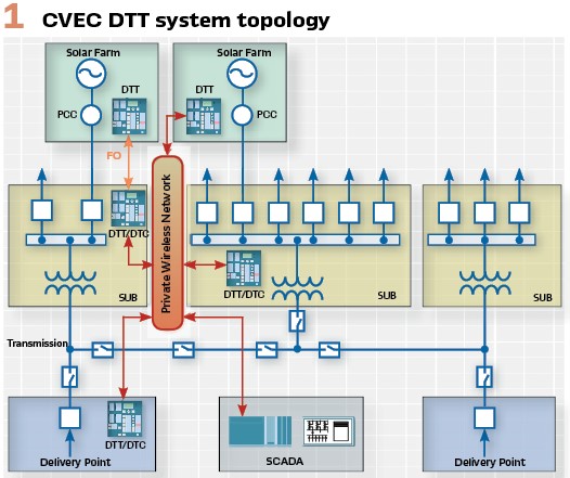
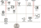
The system topology is shown in Figure 1. System required to provide direct transfer trip signals from the delivery point at the transmission substation or from each distribution substation to the DG sites. One solar site was just over 1000 feet from the substation, therefore direct fiber connection could be used. The other communication links required approximately 27 miles of fiber or copper if used for this system, thus cellular communication infrastructure was the only viable alternative.
The basic building blocks of the system include 7SC80 type DTT controllers and RX1400 cellular modems. The controllers are interfacing with local protection and primary gear though binary inputs and outputs (or GOOSE where applicable). Controllers are directly connected to the cellular modems though an Ethernet link. The modems are responsible to transmit the GOOSE messages between the DTT system components.
The functional design at each of the system locations is unique in its functional logic. The controllers at DG sites govern PCC intertie reclosers (PCC-Point of Circuit Connection). These devices are mainly responsible to receive DTT signals and to disconnect the DG site. The substation SUB-DTT controllers are responsible to receive protection trips from multiple protective devices and communicate open status information from the primary feeder breaker as well as other required DTT signals to a PCC-DTT at DG site. The functional logic example of PCC-DTT controller is shown in Figure 2.
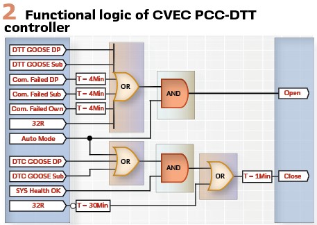
Device initiates a DTT trip on the receipt of a DTT GOOSE from either the delivery point substation or the distribution substation. A reverse power function was implemented to disconnect the DG sites if a possible reverse power condition could occur at the substation delivery point. Logic also monitors the communication failures to the other controllers in the system and disconnects DG if communication is interrupted for longer than four minutes. The system Auto Mode must be enabled to allow a DTT trip to occur. A new Direct Transfer Close (DTC) function was implemented on this system to automatically close the DG site intertie recloser switch subsequent to a DTT trip if the system returned to a normal healthy state for one minute with no reverse power detected for a sustained time. This new intelligent feature had to ensure the DG site was connected automatically without having to wait for an operator to be available, maximizing the possible uptime DG site.
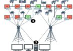
Madison Gas and Electric Project: The DTT system includes three remote DG locations with 5MW, 1.8MW and 1MW sites connected to a 13.8 kV distribution substation through a dedicated feeder. MG&E investigated many different technologies to find an alternative for the transmission of DTT signals. In all instances these technologies could not offer an immediately deployable and cost-effective solution. MG&E decided to contract with Siemens to help develop a DTT solution to transmit IEC61850 GOOSE messages between field devices using cellular communications systems.
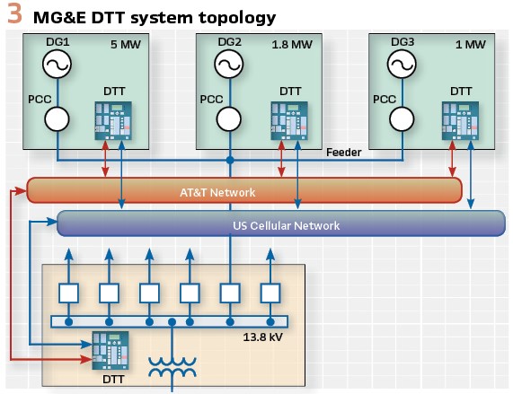
The system topology is shown in Figure 3. System includes DTT controllers governing PCC reclosers at three DG sites. All sites are connected to the 13.8 kV distribution substation, where fourth DTT controller monitors the breaker status and trip signals from multiple relays protecting this circuit. This project includes unique feature employing two independent cellular networks to achieve best possible communication reliability. Every controller is connected to two different modems to cover even hardware failure.
Cellular Communication
To get this new intelligent DTT approach to work in all projects, it is essential that the field and substation devices communicate and share information in real time utilizing IEC61850 protocol. The modern IP based radio systems (Wi-Fi, WiMAX, Cellular 3G, 4GLTE) support Multicast traffic. What makes GOOSE messaging ideal for this cellular application? It is a small packet protocol. Analog or binary information can be shared for processing by the protection and automation controllers. Data traffic can be managed using desired retransmission time intervals of the GOOSE packets. Quality information embedded into a GOOSE message allows receiving devices to filter and discard packets with incorrect quality information.
The cellular communication consisted of three basic building blocks to achieve the required security:
- The first element was to get a Private Wireless Network from the cellular provider. This means that this network is not a public network and not connected to the internet. There is no unsolicited traffic on this network
- The second is Machine to Machine (M2M) Data Plans for the DTT system’s modems. The cellular communication infrastructure is a Layer III network, therefore it is necessary to tunnel Layer II GOOSE traffic between DTT controllers through a cellular network
- The third element is the encrypted IPsec Tunnels. They were setup between all devices using the cellular modems with powerful routing capabilities
The tunnels are very important as they create a virtual wire link between cellular modems of DTT systems.
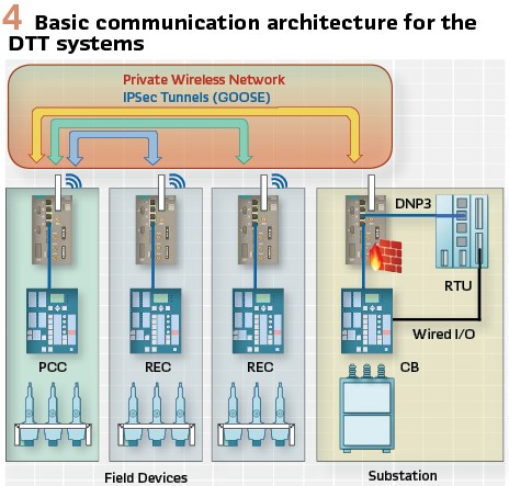
The GOOSE messages are generally broadcasted in Ethernet networks, the tunnels cannot be penetrated by unwanted broadcasted GOOSE packets from other DTT or protection systems. A unique virtual private network (VPN) is also used to separate a DTT applications from all other possible IEC61850 systems. (see Figure 4).
GOOSE Structure & Settings
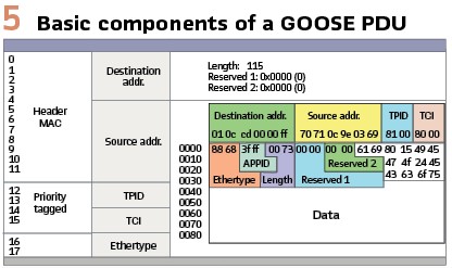
The structure of the GOOSE message as seen from a Wireshark trace with basic components of a GOOSE PDU is shown in Figure 5. Some important components in a GOOSE structure include:
- Preamble and start of the frame, which is done at the hardware level and not shown in the figure
- Fixed 6-byte size destination and source multicast addresses
- Priority tagging to separate time critical and high priority traffic
- 4-byte 802.1Q VLAN (Virtual Local Area Network) comprised of
- TPID – Tag Protocol Identifier
- TCI – Tag Control Information
- Ethertype (0x88b8 for GOOSE)
- APPID identifies GOOSE messages based on their application and is 2-bytes in size
The GOOSE structure and settings were adapted for this solution, making it possible to function on any IP-based communications network (e.g., Fiber, WiMAX, Wi-Fi, cellular, etc.). Some of the key settings include:
- Limiting the GOOSE application types:
- Status – Includes GOOSE messages related to the open/close feedback from all the devices in the system
- Protection – Includes time critical DTT GOOSE messages amongst the devices in the system
- Modifying parameters of each GOOSE application:
- VLAN – Applying the same Layer II VLAN setting for all GOOSE applications
- Max time setting for each application set to the maximum. In normal conditions, the duration for repetitive GOOSE messages are 1.5 times the Max time setting
- Min time setting is customized for each GOOSE application based on the importance. Protection and status applications have sensitive Min time settings compared to the control application
- VLAN Priority for each GOOSE application. Highest priority is given to protection and status applications compared to the control application
These measures guarantee successful delivery of GOOSE messages within a dynamically changing network.
A virtual LAN (VLAN) is any broadcast domain that is partitioned and isolated in a communications network at the data link layer (OSI Layer II). The Layer II VLAN parameter is the key differentiation feature for an IEC61850-based GOOSE message. It is crucial to have a unique VLAN assigned to each DTT system respectively to avoid any duplicates and/or collisions with messages between devices from different systems. Some of the important features of Layer II VLAN include:
- Enhanced Network Security – all the GOOSE messages with a unique VLAN tag are broadcasted within the networks associated on the same VLAN. Each Layer II VLAN can be assigned with a specific Layer III IP address (tunneling) to pass Layer II traffic over a Layer III IP network over a secured communications path (tunnel)
- Network Management – at the recipient device in a multi-device network, VLANs provide networking devices (routers) with a capability to easily filter the broadcast traffic based on their VLAN
- Mitigated Network Congestion – VLANs over Layer III provide separate communications paths (tunnels), which are peer-to-peer and have their own tunnel parameters; thus avoiding any collisions
The transmission of many GOOSE messages over a cellular network poses several challenges, including latency, reliability, data consumption, etc.
The L2TPV3 (Layer II tunneling protocol version 3) VLAN tunnels are configured between the base modem and the end modems to communicate IEC61850 GOOSE messages. The tunnel configuration settings include:
- VLAN Number – same VLAN number associated with the GOOSE messages originating from the respective device
- Session Parameters – identical session parameters on either side of each tunnel
- Local and Remote Ports – unique local and remote ports associated with each tunnel
- Local and Remote Static IP Addresses – local and remote SIM card static IPs assigned by the cellular provider
Communication Security
IPsec is one of the key security features implemented in the cellular modem to provide protection against cyberattacks. For DTT applications, IPsec adds an additional layer of security over the existing L2TPV3 tunnels. IPsec is configured to encrypt/decrypt any data entering/leaving the L2TPV3 tunnel, respectively. IPsec features include:
- Data Encryption (Data Confidentiality) – inbuilt 256-bit AES security algorithms are used to encrypt any data communicated over the cellular network
- Modems verify pre-shared keys (unique key can be assigned for each link) before sending/receiving any data
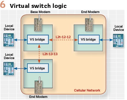
- The hub-and-spoke model shown in the Figure 6 illustrates the tunnel setup among three cellular modems:
- A virtual switch is used in ‘bridge’ mode in each modem to connect the local device traffic with the Layer III VLAN tunnels originating from the modem
- The hub/base modem has a VLAN tunnel to every spoke/end modem, respectively
- The spoke/end modem has only one VLAN tunnel to the hub/base modem
The third party was contracted to perform a penetration test on the RX1400 cellular modem and 7SC80 controller combination in DTT system. The testing was very successful, and no issues were identified. The use of a private network and GOOSE through IPsec tunnels made the system near impossible to penetrate. Remote access to the DTT controller settings and other services is disabled in the 7SC80 and RX1400 making the only possible access point the locked cabinet.
Redundant Communicating DTT
In addition to the security measures, a redundant communication strategy of using independent cellular networks was introduced in MG&E project. This approach provides communication failure redundancy before a DG site would be disconnected. The expected communication availability is 99.9 %. This was only possible if the DTT system could detect and switch to the available network.
A truly redundant system was required much like a PRP system in a substation. The major difference is that the DTT device had to broadcast and subscribe to GOOSE from two different communication networks, ultimately acting as a logic bridge between two IEC61850 Stations. All DTT GOOSE communication are shared simultaneously over both networks. The DTT controllers and the cellular routers are programmed to accept the redundant DTT traffic. The incoming messages from both systems are processed according to a “first come, first served” philosophy in the device logic. This implies that the fastest incoming message will trigger the DTT operation logic and the redundant message is ignored.
- DTT controller configuration – the logic in the DTT controller is designed to accept duplicate inputs and provide duplicate outputs which will be forwarded over separate cellular/fiber networks. Each GOOSE message (incoming/outgoing) is duplicated (individual for each network) to suit the redundant philosophy
- IEC61850 station configuration – two GOOSE applications are created for individual networks. Each application has unique APP Name, VLAN and APP ID. The GOOSE connections between the devices in the DTT system are duplicated in both applications. The redundant messages configured in the controller are separately assigned in their respective GOOSE applications
- Cellular Router Configuration – the L2TPV3 (peer-to-peer) tunnels are defined with VLAN ID of the cellular GOOSE app. These tunnels are bridged with the local cellular interface using the virtual switch defined above
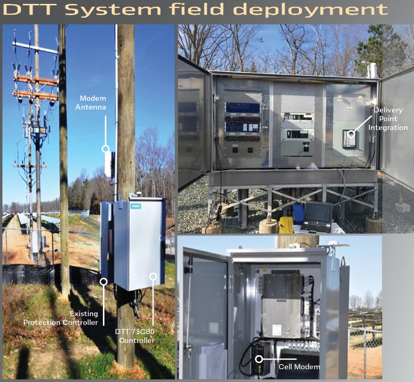
Field installation
The deployment was very similar for both projects and is depicted in the Figure on page 38. The DTT cabinets were designed to integrate with the existing protection controllers associated with the reclosers used for the distribution subs, the inline reclosers and the DG site intertie reclosers. The DTT cabinets housed the DTT controller and the cellular modem/router. The information between the protection and DTT was done using hardware connections. A directional cellular antenna was installed at every site, either on the pole or the substation cabinet or building. In a few instances the antenna was mounted a bit higher on the pole but always under the conductors. The antenna direction at each locating was adjusted to get best RF signals
A few changes had to be implemented to the CVEC system after initial deployment. The logic for communications failure and DTC had to be modified to ensure correct operation of the DTC function. Communication failure supervision logic caused the DTC not to function properly.
The reverse power function also over-operated due to a short trigger time caused by transmission events, but was easily corrected with a delay built into the logic. The permanent communications failure detection time was increased as temporary communications failure events caused unwanted DTT operation. Currently, the system performs as designed with excellent reliability. The DTT speed of operation is well within acceptable limits with times varying between 100 and 200ms on the cellular communications systems. The cellular DTT system proved within the first month that it is more reliable that the leased line system.
Conclusion
DTT over cellular is more reliable as a system than a leased telephone line system. Using IEC61850 and the GOOSE messaging made it possible to design and implement a more intelligent system that can not only disconnect a DG site indiscriminately on a communications interruption, but also determine if a failure was merely temporary in nature and activate a new dynamic state chance protection function to ride through expected communications interruptions.
It was possible to implement a DTC function to automatically close the DG site back after it was tripped off for a temporary fault on the feeder. This new DTT system is designed to keep DG sites connected to the grid.
Biography:

Alexandr Stinskiy Ph.D. is senior applications engineer and technical promoter. He graduated from Pavlodar State University, Kazakhstan, with diploma in Relay Protection and Automation. He defended his thesis “Improvement of Current Protection for Distribution Grid” in 2009. Alexandr holds 19 patents in the area of protection devices and algorithms (including two US patents) and has worked as a consultant in the field of power industry, energy savings and efficiency. After joining Siemens US in 2010, he is involved in Distribution Feeder Automation product development. In his present role Alexandr is promoting Siemens Energy Automation products for utilities in the US.

Suraj Chanda, MSEE, MBA, is applications engineer for Siemens USA where he configures and tests automated electrical power distribution systems. He graduated in 2011 from Texas A&M University, College Station, Texas, USA with Master of Science degree in Electrical Engineering. He defended his thesis, “Modeling the Effect of Hurricanes on Power Distribution Systems” in 2011 at College Station, US. He joined Siemens as an application engineer in 2011. He plays a major role in designing, programming and testing of FLISR projects. Suraj received his MBA degree from Duke University in 2018.