Integrated testing of Superimposed-component and Traveling-wave Line Protection
by Christopher Pritchard, OMICRON electronics, Austria
Fault locators using traveling wave (TW) detection, have been installed for decades and are known for their very high accuracy. The latest developments in line protection are now using TW elements for ultra-high-speed tripping. But beyond the tripping speed TW elements provide some unique advantages as we are moving forward to an inverter dominated power system with less inertia.
The majority of protection elements today operate on phasor based quantities. These quantities are obtained by applying a low pass filtering and analyzing a certain time window, which makes them relatively slow in operation.
In a low inertia power system, the fault current can only be provided for a very short time or not at all, which limits the applicability of phasor based elements. As we will describe in the following article, TW elements are not dependent on the magnitude of a fault current, therefore their speed, dependability and security are not compromised in inverter dominated systems.
In addition, the tripping speed can help to maintain the inertia in the system and prevent significant voltage sacks. With these benefits in mind and the growing amount of inverter in the power system, we can expect a continuous growth in the implementation of traveling wave protection systems.
But with new protection schemes always comes the question: How to test these schemes? When it comes to on-site testing, high sampling rates of 1 MHz and above pose new challenges on test equipment. The high-frequency signals cannot be readily injected via a conventional high current amplifier. This article illustrates, how this type of relays can be reliably tested on site with one single test setup, and which requirements must be met by the test equipment used.
Characteristics of Traveling Wave
Traveling waves are surges of electricity resulting from sudden changes in voltage. They propagate at near the speed of light along overhead transmission lines and feature steep and distinct edges. When caused by a line fault, TWs carry a great deal of information about the fault location and type which has been shown in studies comparing time-domain signals and traveling waves.
Relay Protection Elements
To protect the power system, traveling-wave relays use different protection elements and schemes. To increase the reliability of traveling-wave elements, they are combined with other time-domain (TD) elements, for example superimposed components. As the relays’ behavior during testing should ideally reflect the real operating conditions, it is important that superimposed component and traveling-wave protection elements are tested simultaneously. To better understand the differences between the single protection mechanisms, they are explained hereinafter.
Currently available implementations of superimposed components use an instantaneous incremental quantity, which is obtained by subtracting the present (fault) value and the memorized prefault value (typically several cycles old) in the time domain.
As such, this incremental quantity contains all frequency components present in the fault signal, including the decaying dc offset, the fault component of the fundamental frequency signal, and the high-frequency transients. Based on this principle, directional (TD32) and distance elements (TD21) can be realized.
When it comes to traveling-wave protection elements, the TW32 directional element compares the relative polarity of the current TWs and the voltage TWs. For a forward fault, the two TWs are of opposite polarities. For a reverse event, they are of matching polarities.
The TW87 differential scheme compares time-aligned TWs at both ends of the protected line to define the fault location. For an external fault, a TW that entered one terminal with a given polarity leaves the other terminal with the opposite polarity exactly after the known TW line propagation time (the one-way travel time from one-line terminal to the opposite one).
The General Testing Requirements
Time-domain protection elements highly depend on the power system data. To ensure correct operation of this system-oriented protection, it is vital to also use test methods based on system parameters.
Testing requirements are considerably reliant on the type of test performed. For certification tests, a detailed investigation of the individual protection elements with the most realistic test signals is required.
Those tests are normally performed in a laboratory environment, where access to all devices under test is straightforward and can even be performed using alternative signal paths. Testing in the lab usually includes many individual test steps, so an environment for automated test execution is required.
Commissioning and maintenance tests must be performed in the field, where the effort for testing and test equipment must be justified economically as well. These tests verify correct installation, settings, and operation of the devices. In the field, though, the test signals usually generated from portable test equipment must be applied to the conventional voltage and current inputs at the location of the installed protection devices.
For an end-to-end protection scheme, this implies an end-to-end test using time-synchronized test equipment. The relay settings should not be changed, and the tests involve all protection elements in parallel.
Common testing requirements include testing of all protection elements both for faults inside the zone where the protection operates, as well as faults outside the protected zone like in a reverse direction or on a parallel line. Additionally, tests that validate the fault-locating function should be performed to verify the accuracy for both double-ended and single-ended fault location methods.
Prerequisites for Testing Superimposed-component Elements
Superimposed-component protection elements can be assessed using a dynamic test which correctly simulates the transition from the pre-fault state to the faulted state. For this, the protected line with infeeds on each end is modeled in simulation software. The software calculates the test signals to be injected for a fault which occurs at a predefined instance in time. These signals can be applied to the devices under test using conventional relay test equipment. Using a simulation-based test, it is easy to simulate superimposed load flow or tests with different infeed conditions. By doing so, the behavior of the superimposed-component elements can be extensively verified.
To avoid unwanted relay operations at the end of each test, correct fault clearing should be simulated as well, which includes a realistic opening of the breaker poles where the fault extinguishes at the current zero-crossing.
Challenging Requirements for Testing Traveling-wave Protection
Traveling wave simulation must be performed at very high sampling rates above 1 MHz. Generating test signals in this frequency range requires considerable computation and memory. In addition, a realistic and detailed model is needed to simulate realistic high-frequency phenomena in power systems. This includes suitable models for transmission lines, cables, and any terminating equipment.
To apply such high-frequency test signals to the devices under test, the test equipment must also be able to create signals in the megahertz range. Today, test sets and amplifiers which inject nominal quantities at nominal frequency into the relay’s current and voltage terminals have a limited bandwidth. Power amplifiers with bandwidths in the hundreds of kilohertz range are expensive and complex to implement. Additionally, such devices are very large and unpractical for field testing.
In the laboratory and during development, it is possible to inject high-frequency samples using low-level signals or even digital signal inputs. In the field, a dedicated test set can be used to inject TW pulses. These pulses simulate the sharp changes of the currents and voltages due to the existence of a TW. The protection device detects the TWs by filtering out these steep edges. In this manner, it is possible to activate the TW elements. The exact arrival times of the pulses are extracted from the TW.
Therefore, the test equipment must be able to inject TW pulses with a time resolution in the nanosecond range, even for distributed injecting ends of an end-to-end scheme in the field. In addition, the test set must have the ability to apply current pulses with a rise time shorter than approximately 5 µs, a magnitude of several amperes, and a halfway decay time longer than 0.3 ms.
The pulses must be injectable in all three phases simultaneously with a scatter below 1 µs. To simulate through faults and reflections, the test set must be able to feed in at least two consecutive current pulses. For end-to-end testing, synchronizing the time of the first TWs between two test sets must be possible with an accuracy better than 1 µs.
The TW signals should preferably be superimposed on the conventional lower frequency current and voltage signals to test other supervising time-domain elements at the same time.
Integrated Test of Superimposed-component and Traveling-wave Elements
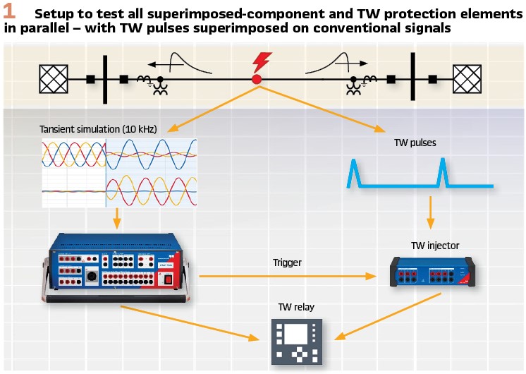
An integrated test using TW pulses superimposed on conventional signals assesses all TD and TW elements with settings and conditions exactly as they are present during normal operation. The generation of the conventional signals to test the superimposed-component elements as well as the timing of the superimposed TW pulses are controlled by the test set, which is synchronized to a precise time source. The TW pulses to test the traveling-wave elements are generated with a separate TW pulse injector (Figure 1).
End-to-end Test with a Single Test Application
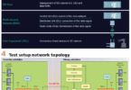
An end-to-end test in the field requires injection of test signals on both line terminals at very different geographic locations (Figure 2).
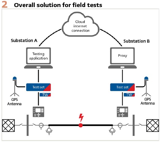
The test software simulates the primary power system and calculates all required signals, including timing and polarity of the TW pulses. The same PC and software can control multiple protection test sets, which use the conventional amplifier outputs for the transient signals (sampled at 10 kHz) and a simple TW pulse generator extension device for superimposing the TW pulses. For precise timing, the protection test sets are time-synchronized using GPS clocks.
The software can control all injected signals at all line terminals simultaneously, both the conventional ones and the superimposed TW pulses. All calculated test signals are first downloaded to the test sets from the computer with the control software.
To verify the correct and precise behavior of the fault-locating functions, the timing precision of the TW pulses is of highest importance: 1 µs timing error results in an error of about 300 m (900 ft) in the fault location. With GPS clocks, the time difference between the two test sets can be kept within the nanosecond range, which equals some few meters on the line.
Advanced test cases of this approach include nonhomogeneous and series-compensated lines as well as mixed overhead line and cable connections. The setup can also be extended for multiple ends.
This test system has successfully been used several times in the field during commissioning.
Carried out Sample Test Cases
The following three simulated test scenarios demonstrate how the TD and TW protection elements work together in detail in case of a fault.
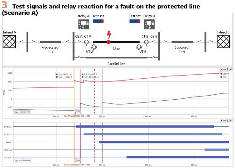
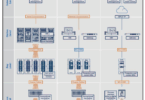
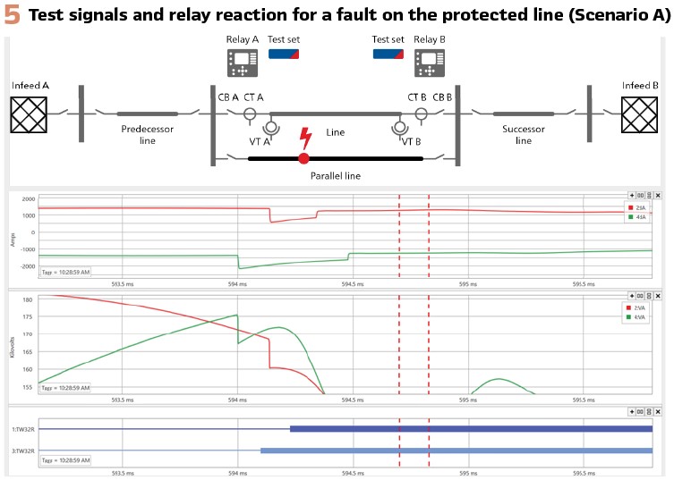
In scenario A (Figure 3), a fault happened 30 percent down the protected line from the left terminal. The first-arriving TWs are simulated with positive current, and negative voltage pulses. The TW32 elements at both line terminals detect the fault in forward direction. There are no exiting TWs visible after the propagation delay time of the line, so the TW87 elements assert accordingly.
Additionally, the TD32 elements declare the fault in the forward direction (using the superimposed quantities from the injected conventional signals). Therefore, both protection elements operate.
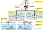
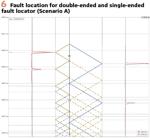
The first-arriving TWs have a time delay of 136 µs between the left-hand terminal and the right-hand terminal. This corresponds exactly to the difference resulting from the fault location (line length of 100 km). Additionally, the first reflected TWs from the fault location back to the relay locations at both line terminals are also simulated so that both the double-ended and single-ended fault locator can be tested at the same time. The Bewley diagram (Figure 6) shows that the single- and double-ended fault location are identical.
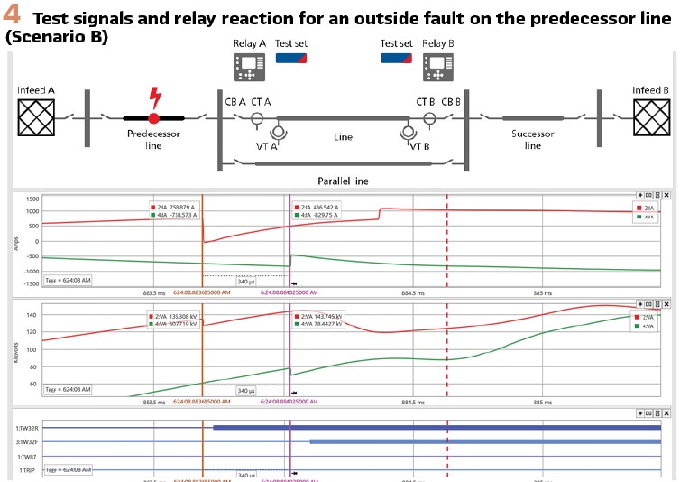
Test scenario B (Figure 4) demonstrates an out-of-zone fault behind the left-hand terminal of the protected line. In this case, the first TWs arrive at the left-hand terminal with negative polarity for both the current and voltage.
Thus, the left-hand terminal relay’s TW32 element declares the fault in the reverse direction. At the right-hand terminal, the current pulse is simulated with positive, and the voltage pulse with negative polarity. Therefore, the TW32 element declares the fault in the forward direction.
The direction of the fault is detected by the TD32 elements in the same way. However, for this fault, the time delay between the left-hand terminal and the right-hand terminal is exactly equal to the propagation delay time of the line. Therefore, the TW87 element does not assert, and the relay does not trip.
In test case C (Figure 5), an out-of-zone fault happened on the parallel line. The polarity of both the current and voltage TW pulses is negative at both line terminals. Therefore, both TW32 elements assert in the reverse direction. The same direction is declared by the TD32 elements. Additionally, there is a second TW pulse associated with the exiting TW at each of the line terminals, arriving precisely after the propagation delay time of the line.
Thus, the TW87 elements remain stable and the relay does not trip.
Biography:

Christopher Pritchard Dipl.-Ing. (FH) was born in Dortmund / Germany. He started his career in power as an electrical energy technician. Christopher received a diploma in Electrical Engineering at the University of Applied Science in Dortmund in 2006. He joined OMICRON electronics in 2006 where he worked in application software development in the field of testing solutions for protection and measurement systems and is now the responsible Product Manager for system-based testing solutions.
.