The next step towards improved engineering efficiency
Jorg Reuter, Helinks LLC, Switzerland
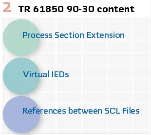
The technical report (TR)
“TR IEC 61850 90-30. Guidelines for IEC 61850 Function Modeling in SCL” has the objective to increase the efficiency of the IEC 61850 engineering process.
It can be considered being an enabler for a more formalized and standardized IEC 61850 specification process. The TR reaches this objective by:
- Extending SCL to formally describe (nearly) all aspects of the IEC 61850 configuration in an IED independent way. This includes the exchange of data and the specification of protocol parameters independently of specific IEDs
- Extending SCL with additional file types, relations, and versioning information to support the workflow between the specification and implementation phase
Introducing a more advanced “Templating Concept” into SCL to allow utilities to formally describe engineering standards and templates
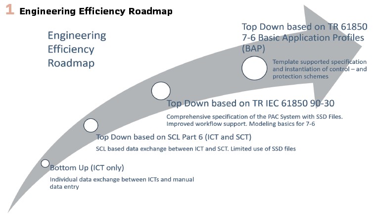
TR 61850 90-30 is not standing isolated. It is extending the engineering process as defined in Ed 2.1 part 6 and is preparing the ground for the formalized definition of Basic Application Profiles (BAP). This is ongoing work in WG10 TR 61850 7-6 Basic Application Profiles. (Figure 1).
The TR 90-30 SCL extensions are aiming to improve the IEC 61850 specification phase by providing a formalized way to specify in the context of the electrical process, Functions, Protection- and Application schemes, and IED Specifications.
The IEC 61850 Engineering Process as it is described in Part 4 and Part 6 of the IEC 61850 standard is extended with more details on the specification phase and the interaction between specification- and system integration phase. (Figure 2).
Why is TR IEC 61850 90-30 important for Utilities?
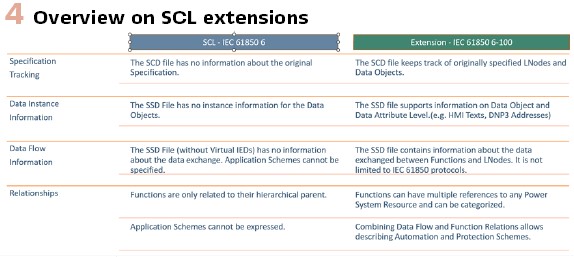
Edition 2.1 of the standard is focusing on the IED – and system configuration aspects of the engineering process. Never the less, already in Edition 1 of the standard the engineering process introduced a formalized specification phase by defining an SCL file called SSD. SSD stands for System Specification Description. Up until now this file has scarcely been used in power automation projects because of two major reasons.
- The information content of an Edition 2.1 SSD file is limited to a static description of the electrical system and the required Functions and Logical Nodes. The information content is just not worth the effort to create an SSD file. In addition to the SSD file utilities still have to provide the specification of protection- and automation schemes, parameters, signal and protocol implementation details etc.
- The current IEC 61850 engineering process definition in the standard is not covering the engineering workflows related to the specification phase and the transition from specification to implementation.
TR IEC 61850 90-30 enables Utilities to create powerful SSD files that are formalized specification files, covering nearly all aspects of an IEC 61850 based PAC system.
The overall efficiency of the IEC 61850 engineering process can be improved by using templates based on the TR IEC 61850 90.30 SCL extension.
New SCL Elements in the SCL Process Section
This part of the article introduces some new XML elements or extensions of existing elements defined in TR 61850 90-30. Be aware that not all elements and relations defined in TR 61850 90-30 are discussed in this chapter.
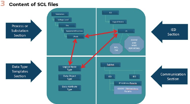
The content of SCL Files: All SCL Files have potentially four different sections. (Figure 3).
- The Process/Substation Section
- The IED Section
- The Data Type Section
- The Communication Section
In the context of this article, we are using the notion Process Section to refer to the Process/Substation section. The new elements, introduced by TR 61850 90-30 are all located in the Process Section. These elements are covering (Figure 4):
- Applications and Functions
- Data exchange with Source- and Control Refs
- Protocol parameters described by Service Properties
- Advanced Logical Node and Data Object mapping information (Specification Tracking)
- Process Resources
Namespace for TR 90-30 SCL Extensions
For now, the extension to SCL defined by TR 61850 90-30 and TR 61850 7-6 (BAP) are defined in a separate XML namespace. For now, this namespace is called
http://www.iec.ch/61850/2019/SCL/6-100
Once the work is terminated, it will be integrated in the regular SCL namespace. This is intended to happen with IEC 61850 Edition 3.
Functions
The notion of Function has been omnipresent in IEC 61850. But only since Edition 2 Functions found their way into SCL as essential elements of the Process Section. They serve as container for Logical Nodes and can have internal structures (SubFunctions). Functions are allocated on every level of the Process Section and when implemented by IEDs, they can spread over multiple IEDs.
TR 61850 90-30 now allows to group Functions into categories and, most important, Functions can be associated to Applications.
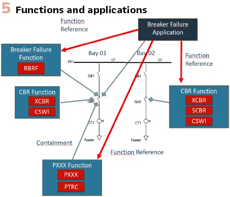
Figure 5 – Functions and Applications, shows some examples of Functions. The Circuit Breaker Function (CBR Function) is a child of the Conducting Equipment QA0 in Bay 01. It contains 3 Logical Nodes. Once implemented in a Process Bus solution this Function could spread over 2 IEDs. The XCBR and SCBR are implemented by the Process Interface Unit (PIU) and the CSW is implemented the bay Controller.
Functions and Applications
A Protection – or Automation scheme is defined by a group of Functions and the data exchange between these Functions. In TR 61850 90-30 we call this an Application and define it as follows:
An Application is a group of related Functions which are communicating to implement the functionality of the Application. Applications can be associated to Process Section elements in the same way as Functions. One Function or SubFunction can be part of several Applications. Applications can be nested.
The Breaker Failure Application in Figure 5 is allocated to the Circuit Breaker QA0 in the Bay 01 because it is responsible to react on a failure of this circuit breaker. In this example 4 different Functions are involved in the Breaker Failure Scheme. These are:
- The Breaker Failure Function with the Logical Node RBRF and
- The Circuit Breaker Function of the protected circuit breaker
- A Protection Function that issues the trip for the circuit breaker and thus initiates the Breaker Failure Function
- The Circuit Breaker Function of the surrounding circuit breakers, because they are opened if the circuit breaker in bay 01 fails definitively
In our example we just have 2 bays. Only the circuit breaker of Bay 02 needs to be operated by the OpEx signal. In a real project we would have multiple feeders where we need the external trip. BAP is defining mechanisms and data model extensions to automatically extend an application to an undefined number of participants. BAP uses elements as Selectors and Cardinality information for this purpose. Details on this are beyond the scope of the current article.
For this scenario, TR 61850 90-30 introduces the XML element Application and allows this element to reference the participating Functions (Function Reference). A Function can participate in different Applications. It can be referenced multiple times.
Data Exchange Specification
A Function is included as a participant in an application, if there is any data this Function exchanges in order to implement the protection- or automation scheme.
The data exchange between the Functions of an Application is implemented either by an external protocol (MMS Reporting, GOOSE, SV, wires) or, in case of 2 Functions residing inside the same IED, it can just be an internal connection.
In our example the trip may be sent by GOOSE, as well as the Operate External for the surrounding circuit breakers. The Internal Operate of the Breaker Failure Function (Logical Node RBRF) may be configured or even hard wired inside the IED. Even if this is not a 61850 protocol-based data exchange TR 61850 90-30 allows including this data exchange in the specification of the Application.
Adding data flow information to the Process Section allows describing the data exchange of Functions independently of the implementing IEDs. The data flow inside and between Functions is modelled on Logical Node level.
The data exchange between Logical Nodes can represent a status, a measured value or a configuration value, but it can also represent a command. In the first case TR 61850 90-30 defines the SourceRef element, in the second case it is the ControlRef element.
SourceRef
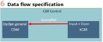
SourceRef stands for Source Reference. (Figure 6).
The SourceRef is a link from a receiving Logical Node back to a source Data Object or Attribute in a Function of the Process Section.
The Source Reference is conceptually very close to the ExtRef. The difference between Source References of LNodes and ExtRef is:
- The Source Reference points to a Data Object, Data Attribute or LNode following the LNodetype specification of an LNode in the Process Section. The pointer is contained in the attribute “source”
- There is no reference to IED communication structures (Control Blocks). Instead, the SourceRef can be related to a Service Specification. The Service Specification allows to define parameters of the required protocol
- The Service indication can include Wiring and IED internal communication, because the data exchange described by SourceRef is not necessarily implemented by an IEC 61850 protocol
The Data Flow specification is independent of the device allocation (Allocation of Functions to IEDs). Once implemented it may be realized by IED internal communication, GOOSE Messages, MMS Reporting, Control Services, SMV or even wires. The Service can be specified by the serviceType attribute of the SourceRef.
The information content of a SourceRef element goes beyond the pure data exchange specification. It has a life cycle and changes its status during the specification and engineering process.
A SourceRef element can be “open” or “connected.” Open means that the SourceRef is defined as input for the Function but is not yet connected to the source of the data. This corresponds to the ”Later Binding” concept for ExtRefs.
The SourceRef element has additional attributes that support the specification and the implementation phase of the engineering process:
Specification Phase
- An “input” attribute that defines uniquely the SourceRef in the context of its Logical Node. The value of the ”input” attribute as well as the description attribute serve as semantical hint for the engineer to properly link the SourceRef.
- Support for the specification of Applications by providing preferred Logical Node, DO and DA information. These attributes help the engineer to find the appropriate source data for the SourceRef. This is helpful for the manual Application design, but it is also intended for the automatic Application instantiation defined in TR 61850 7-6.
Implementation Phase
- Specifying the requested service and protocol parameters for the implementation
- There is, once the LNode is mapped and the communication is configured, the possibility to link the SourceRef to an ExtRef of an LN. This link documents in an SCD file how a specified data exchange has been implemented in the system
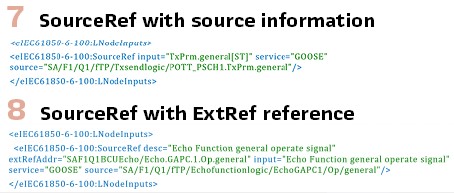
Figure 7 is an example of a connected SourceRef. The source attribute has been set during the specification phase.
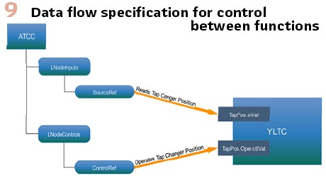
The implemented SourceRef of Figure 8 is how a SourceRef may look like in a properly configured SCD file. The “extRefAddr” attribute points to the source of the data in the sending IED.
ControlRef for Controls
The Control Reference is a link from a controlling Logical Node to the controlled Data Object or Attribute.
Control References are referencing I-Group (e.g. ITCI or IHMI) Logical Nodes without Data Object/Attribute specification or, similar to SourceRef they also can refer to any other Logical Node that performs control operations. (Figure 9).
Data Object and Attribute Instances for LNodes
Adding instance information to the specification is an important step to allow much richer SSD files.
Specifying parameter values and attribute values of Logical Nodes is an important part of a comprehensive Functional Specification. Parameter values are very often instance specific.
TR 61850 90-30 defines new elements named DOS (Data Object Specification), SDS (Structured Data Specification) and DAS (Data Attribute Specification). These elements are children of the Logical Node. They correspond to the LN instance data of the IED data model. With these new elements values can be added to the Data Attributes of every LNode instance in the Process Section.
Furthermore, it is possible to add protocol mappings as they are defined e.g. in TR IEC 61850 80-1 for IEC 61870-5-104 already to the specification. Utilities now can formally add their 104 addresses to the SSD file.
Specification Tracking
The idea of specification tracking is to support the documentation of implementation decisions that the system integrator takes during the creation of an SCD file. TR 61850 90-30 provides several places to document and track the implementation decisions.
There are new attributes to the Logical Node. These attributes store the originally specified Logical Node.
If, for some reason, the system integrator is forced to implement a Logical Node different from its specification the customer can compare the mapped Logical Node in the SCD file against the specified one.
In case a different Logical Node has been used to implement a data point, generally also a different DO/DA must be used. This can be tracked by the customer due to the new DOS/DAS elements.
Virtual IEDs
Virtual IED Definition in TR 61850 90-30: In this article the virtual IED definition is not requiring changes in SCL (Edition 2.1) except for some additional attributes of the IED element and the Header element.
Virtual IEDs can serve 2 different purposes:
- As specification for a physical IED
- For simulation purposes (Digital Twin)
ISD Files
Virtual IEDs are very much like ICD or IID files. The extension for a virtual IED is “. ISD”. ISD stands for IED Specification Description
The main difference between ISD files and other IED describing SCL files (ICD, IID, CID) does not lay in the SCL structure but in the role of the file in the engineering process and partly in the semantics of the SCL elements.
Identifying and referencing SCL Files and IEDTypes.
A controlled Engineering Process requires careful management of the participating SCL files. Being able to identify and reference files and their revisions is the purpose of the following extensions.
The identification of files is done by versioned UUIds. Different versions of a file are distinguished by a version attribute. The UUID for different file versions remains unchanged.
Examples of Referencing SCL Files
In the context of a PAC project SCD files can have a reference to the related SSD file. This reference is contained in the Header element- The attribute is “ssdRef.”
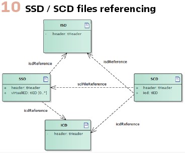
The IED instances in an SSD File can have references to ISD and ICD Files. The SCD references the SSD File. (Figure 10).
Practical experiences with TR 61850 90-30
Osmose: As part of the European Funded Research Project Osmose TR 61850 90-30 has been successfully applied on the IEC 61850 engineering process in this project.
OSMOSE has the goal to provide a demonstration of system integration with smart transmission grid and storage technologies with increasing share of renewables. (Figure 11).
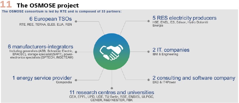
SCTs and ICTs from different vendors have been used to model, specify and implement an 61850 based battery storage application.
UW 2030 by Stromnetz Hamburg (SNH)
Stromnetz Hamburg (Germany) is running a digital substation innovation project implementing new technologies.
The specification data model is delivered as an IEC 61950 SSD file. It is based on typical feeder arrangements and includes the structure and IEC 61850 naming for the Power Equipment, the Electrical Connections and the allocation of the IEC 61850 Functions and Logical Nodes.
The Logical Node types are taken from an SNH (Stromnetz Hamburg) specific private namespace.
According to TR 61850 90-30, Data Exchange and Function Parameters are added to the Substation/Process section. The Function Templates may contain unbound SourceRefs(inputs). During the definition of the Application Schemes, the Source attributes of the inputs are resolved. The Function Parameters are defined on the Data Object resp. Data Attribute instances (DOS / DAS) in the Substation/Process section.
Virtual IEDs are derived from the Substation/Process section. The Logical Device hierarchy is built based on functional testing requirements and is reflected in the Virtual IEDs. Functional Naming (ldName) and Flexible Naming (LN Prefix and Inst) is applied. The Virtual IEDs define the required services and contain specifications for Data Sets and Control Block configurations.
In the Communication Section, Process- and Station bus are defined as well as the required network settings and IEC 61850 network connections for MMS Reporting, GOOSE and Sampled Values.
The SSD file describes a highly formalized and comprehensive data model that is binding for the contractors. The contractors are expected to deliver a corresponding SCD file, that allows to formally compare the degree of the specification fulfilment.
Elia “Virtual Substation”
Elia as a Belgium system operator has started an innovation project called “Virtual Substation.” One of the goals of this project is to highly automate the IEC 61850 engineering process. A proof-of-concept sub project is focusing on this goal (POC Engineering)
- Using SCL extensions from IEC61850-90-30 (former 6-100) (function modeling) and 7-6 (BAP), including Osmose feedback
- Introducing
- Function- and application specification (FSD/ASD)
- EID specification (ISD)
- Specification of logical behaviour using IEC61131(BehD)
Conclusion
TR IEC 61850 90-30 enables Utilities to formally specify their IEC 61850 PAC System in a device independent way. It provides a solid base for the successful implementation of an SCL driven top-down engineering approach an prepares the way for working with Basic Application Profiles. This will revolutionize the way we implement automation- and protection schemes.
Biography:

Jorg Reuter – After earning his master’s degree in electrical engineering from the University of Kaiserslautern/Germany Jörg entered the world of Industrial Process Automation to explore his passion for Real Time Operating Systems and Process Automation.He spent the last 20 years learning about the Utilities requirements and challenges in engineering IEC 61850 based protection and control systems as software developer. R&D Manager and CEO in different companies. Currently, he works as a Director and Owner of Helinks LLC Switzerland, where he is focused on IEC 61850 Engineering Tools and the IEC 61850 Engineering Process. As a member of TC57 WG10 he is actively involved in the further development of the IEC 61850 standard.