IEC 61850 has always included test functionality, but it has not always been well understood or implemented. Let’s explore how it can be done by using functionality available since Edition 2 of the standard.
By Daniel Abetz, Siemens Ltd., Australia
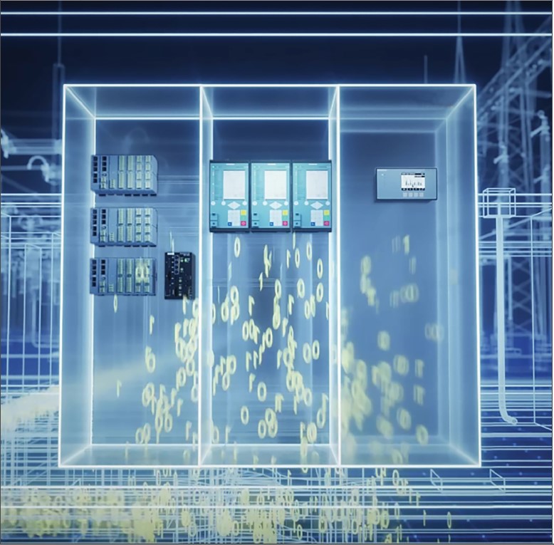
In the initial release of IEC 61850 in 2004, there was limited explanation in the standard for the testing of functions and messages within a substation automation system. Early adopters of the standard often designed their own-so called ‘GOOSE isolation schemes’ which lead to unwieldy and customer centric solutions. Many users found that they were unable to easily expand these substations at later stages.
Some users abandoned the use of IEC61850 altogether as a result, reverting to hardwired signaling between IEDs and the use of other protocols such as DNP3 for SCADA communications.
These operational requirements were seriously studied and considered in the second edition of the IEC61850 standard, leading to many beneficial changes. One of the key changes was the introduction of supervisory logical nodes (LGOS and LSVS) to enable constant, automatic monitoring of communications between IEDs. Additionally, the second edition of the standard clarified the use of quality attributes for each data object within GOOSE messages and the mandatory handling of data quality by IEDs. This provided a uniform approach to testing of protection functionality and GOOSE messaging, eliminating the copious amount of logic previously used for manual GOOSE testing schemes, providing a uniform approach that test technicians could use across multiple IED vendors and multiple end users, thus reducing the risk of testing errors.
Simulation vs. Test Modes
Clarification is needed for many users as to the purposes of simulation and test modes along with the difference between the two. A simple ‘rule of thumb’ that can be applied is that only test equipment (e.g. a device simulating a relay) can generate a message with the simulation flag, and an IED is never able to send ‘simulated’ messages. Section 7.8 of IEC 61850 7-1 describes the data required for testing, and clearly defines how test processes should work. Further, the Table A.2 in Annex A of IEC61850-7-4 provides very clear guidance on how functions shall operate on receipt of data of varying quality and is a good starting point for design and commissioning engineers looking to improve their understanding of testing with IEC 61850.
Simulation Mode: The purpose of simulation mode is to allow an IED to subscribe and process simulated messages in preference to the actual messages on a network. This allows users to test individual devices by injecting simulated GOOSE and SMV packets into the network without disturbing the operation of other devices that are subscribed to the same messages. Key examples of this are merging units publishing SMV streams and GOOSE messages that are used by both the busbar and feeder protection IEDs, and a user wishing to test the line protection whilst leaving the busbar protection in service.
To enable a device to process simulation data there is a single control point for each device, the data object Sim located in LPHD1. This data object is optional, and devices need not support simulation mode to be compliant with IEC 61850, however, it is impractical for the test and commissioning engineer to perform work in a live system without this feature being supported by all devices.
To facilitate smoother testing, once a device has subscribed to a simulated message, it shall not revert to the actual message until Sim.stVal=false, even if the simulated message is no longer available on the network. This allows the test set to be reconfigured without the device under test reacting to actual data from the system and is clearly described in the state machines provided in IEC 61850 -7-1 Section 7.8.2. Some test equipment can generate simulated messages without asserting the simulation flag in the message, and this can be useful under some conditions. However, the use of this functionality should be used with extreme care, especially when in a live substation environment.
Input Signals Used for Testing: There are two main ways that the standard provides to control the use of test data within functions. The first of these is described in IEC 61850-7-1 Clause 7.8.3 which makes provision to switch the inputs of a function to dedicated test signals via the use of InRef data objects. It is possible to define a standard source reference (setSrcRef) and as well as a dedicated test signal (setTestRef) and then to use a tstEna attribute to switch between these references. However, this is not regularly used in practice and is not available in (m)any IEDs.
Test Mode: This is the most common method for testing within an IEC 61850 based substation. The concept is introduced in IEC 61850-7-1 Clause 7.8.4. It is important to clarify that the mode and behavior of a function are not necessarily the same – the behavior is affected by the mode, but behaviour is also inherited from the hierarchy of logical devices. As such, a particular logical node may have Mode=on whilst the Behavior=test if the mode is set to test at the device level as will be described later.
When the behavior of a logical node is test, all data objects at the output of the logical node will have the test attribute of the quality asserted indicating that this data is produced by a function under test and may not represent the actual process value. Logical nodes process the quality of their incoming data objects according to Annex A of IEC 61850 -7-4, allowing test engineers to set up test procedures for the system and devices under test. To summarize the table, logical nodes with beh=test will accept incoming data objects whether the q.test=true or false. However, logical nodes with beh=on should treat all incoming data with test=true as ‘invalid,’ providing an isolation point for test procedures. This break in the processing of data is analogous to an isolation link in a hardwired substation.
Messages generated by test equipment may optionally assert the test attribute of the data objects in the messages they are simulating which may be useful for some test conditions.
A short Note on ‘blocked’ Modes: For newcomers to the standard, it is worth noting that if the behavior of a logical node is blocked or test/blocked, it will not drive binary outputs of device. However, this blocked behavior does not flow through the quality attributes of the data objects at the output of the logical node. This means that the next logical node in the chain of data will still be able to operate the binary outputs of the device. Care should be given as to how the blocked behavior is used during testing. To be on the safe side, an entire device can have the mode set to blocked, which will affect all the outputs of a device. Alternatively, individual functions (logical nodes) can be set to blocked, but then care must be made as to how outputs are mapped. Ensure that Operate signals from protection functions are routed through the circuit breaker logical device and are not mapped directly to binary outputs on the device.
Levels of Control
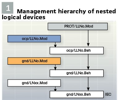
Since Edition 2 of IEC 61850 was published, it has been possible to ‘nest’ logical devices within other logical devices via the ‘GrRef’ data object in LLN0 of each logical device. This allows a hierarchy of logical devices to be created within an IED, such that modes and authorities may be controlled at a single point, and inherited to all lower elements within the hierarchy, as shown below in Figure 1. Here, controlling the mode of the uppermost logical device (PROT) will have a flow on effect on the behavior of the lower logical devices (‘ocp’ and ‘gnd’), and the logical nodes contained therein.
Using this functionality, it is possible to place sections of the hierarchy into various modes and leave others in service, i.e. in the ‘on’ state. Modern IEC 61850 based protection relays such as SIPROTEC 5 devices support this hierarchical approach, along with the control of individual logical devices and nodes within them.
By having this hierarchical approach, it is possible to place individual functions or logical devices into test mode so that testing can be performed on portions of an IED, which is particularly useful for centralized protection schemes.
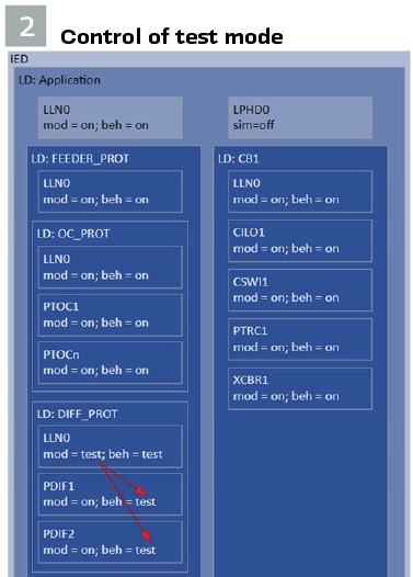
In the simplistic example below, the line differential protection functions within the device are placed into test mode whilst leaving the overcurrent protection and circuit breaker functions active. To perform this, a single command (SCADA or IED function key) is required to place the differential protection logical device into test mode. This could reasonably be applied during commissioning of a device where an end-to-end test of the line differential scheme needs to be undertaken. By placing just the differential functions into test, the backup protection functionality remains available during this testing.
Another scenario is the ability to place a single logical node into test mode. Although this may at first seem to be of limited usage, it provides a very good isolation point to prove the receipt of external data when the test attribute is asserted. (Figure 2).
Design for the Full Lifecycle
A good designer will consider the full lifecycle of a project, including replacement of failed devices, maintenance of equipment, changes to network configurations, etc. This may entail a slightly more complex design process, but the result is a considerable improvement in the operability of the substation automation system. An example of this is to consider how future bays can be added to substation without the need to reprogram all other IEDs on the same bus to incorporate the new IED(s) into the circuit breaker fail scheme or a reverse blocking scheme.
As part of this design, consideration of routine tasks such as the end-to-end testing of line differential schemes, device replacements and IO checks should be considered. During the design phase, it is recommended that a lab will be established to prove the intended operation of these tasks. Though this may increase up front design effort, the payback is that the commissioning effort should be greatly reduced. Once a design is proven, it may be templated and reused for future projects as with conventional designs.
Typical Use Cases
Simple CBF Scenario: In conventional substations, tests are conducted to defined isolation points with multiple tests being run to prove the overall performance of the system. The same philosophy is to be applied to digital signals with IEC 61850, with the network being considered as part of the overall protection system and a defined isolation point.
In conventional substations, tests are conducted to defined isolation points with multiple tests being run to prove the overall performance of the system. The same philosophy is to be applied to digital signals with IEC 61850, with the network being considered as part of the overall protection system and a defined isolation point. (Figure 3).
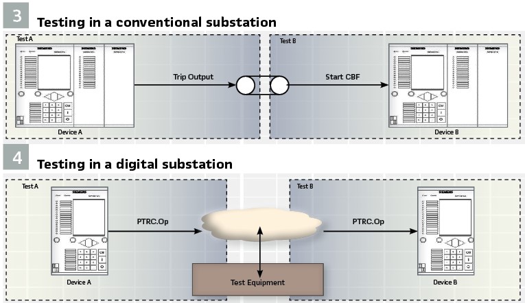
In a digital substation, Test A can be completed by placing Device A into test mode and generating the conditions for a trip. The test equipment can monitor the network for the required GOOSE message and measure the time to receive PTRC.Op.stVal=on. As the test quality attribute will be true, the operate signal will be ignored by Device B. (Figure 4).
The initial conditions required before Test B can be undertaken, are to set LPHD1.Sim=on and LLN0.Mod=test (or test/blocked) at Device B. Device A will remain untouched for this test. Next, a simulation device is added to the network and injects a GOOSE message matching that of Device A with the exception that the simulation shall be set. Device B will process the simulated message instead of the actual message and any actions can be checked as required. When combined with GOOSE supervision, the scheme is fully tested and correct operation can be guaranteed.
Hence, by combining the use of Test and Simulation modes it is possible to perform in service testing of devices without interrupting the remainder of the protection system and without needing to disconnect them from the network.
Breaker and a Half Process Bus Scheme: Process bus substations add a new complexity to the digital test scheme, as there is more data presented on the network. However, as there are far fewer physical connections to the protection IEDs, testing is also simpler in that fewer connections need to be made to the panel wiring which improves testing efficiency. With everything being digitalized, it allows for more creativity with automated test plans as there is no need to rewire equipment between test scenarios, vastly improving efficiency.
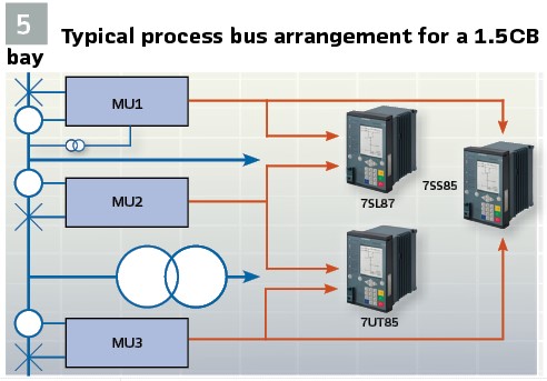
The scenario given in Figure 5 is a typical arrangement for one protection scheme in a breaker and a half switchyard. In this scenario, the SMV streams from each merging unit are used by two protection applications. This requires careful consideration of how to configure the SMV streams and the receiving IEDs to allow for testing with simulated streams. It is useful to have an IED that can be logically ‘disconnected’ from an incoming SMV streams under some situations. Not shown in this figure are two additional merging units connected to the busbar VTs.
There are several test scenarios that should be considered:
1. Commissioning of the substation
2. Replacement & testing of protection IEDs
3. Replacement & testing of a merging unit
4. Expansion of the station, by the completion of a bay or addition of a new bay to the substation
To replace or test a protection IED requires the use of simulated SMV streams. It is not possible, nor necessary, to perform secondary injections on the merging unit to test the protection IED, as this will disturb the other protection systems in the substation. The first step is to place the protection IED into test mode and then simulation mode, using the 7SL87 for this example. After placing the 7SL87 into simulation mode, it is possible to briefly simulate the SMV streams from MU1 & MU2 which will disconnect the 7SL87 from the incoming streams. Henceforth, it is then possible to simulate just one SMV stream from the test set which is generally easier to manage. Similarly, any GOOSE messages can also be simulated to facilitate the testing. IEC 61850-10-3 provides some guidance on this topic and provides an example where two SMV streams can be published by the merging units, but this creates additional network bandwidth without much gain when there is one protection application per IED. Consideration needs to be given to how the outgoing GOOSE messages, particularly to the merging units, are best tested.
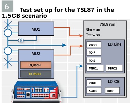
The outgoing GOOSE messages should be performance tested by the protection test equipment. Additionally, by using external tripping logical nodes in the merging unit, it is possible to manually prove receipt of the correct data during the testing by placing the relevant logical node in the MU into test mode. For this to be practical, merging units shall have an individual external trip function for each connected protection application, e.g. MU2 must have a PSCH logical node for the incoming trip from the line protection, and another for the incoming trip from the transformer protection as shown in Figure 6. It should be noted, however, that with GOOSE supervision it will be possible to also prove that GOOSE messages from the newly installed (or tested) IED are being correctly received at the subscribers.
The replacement of a failed merging unit is somewhat more problematic and depends on the ability of the IED to respond to missing SMV streams. The normal action for a protection IED is to block all relevant protection functions when an SMV stream fails. However, it is ideal if an IED accepts a manual intervention to ignore the missing stream as this will allow the network to operate to modify the primary equipment states such that no current is flowing through the CTs after which a command can be given to the IED to ignore the missing data. This will reinstate the affected protection schemes (e.g. if MU2 were to fail, it would place the line and transformer protection back into service rapidly), thus allowing the network operator to plan the replacement of the merging unit. This feature is implemented in the SIPROTEC 5 protection IEDs as ‘measuring point disconnection’ and gives great flexibility to network operators.
Merging unit replacement involves bench testing including SMV and GOOSE message checks. The replacement device shall be placed into test mode prior to connection to the substation network, after which it should be checked that all communication supervision alarms within the substation are cleared. A subset of tests may be tested if desired, but is not strictly required.
To expand a substation, either by adding a new bay or a new bay requires re-engineering the SCD to incorporate the additional IEDs. A good design will minimize the number of IEDs that require modification, thus minimizing integration and testing effort.
Benefits of a Digital Substation
By definition, devices in a digital substation exchange data over a digital network rather than through hardwired interfaces. By eliminating these hardwired interfaces, many potential sources of error are removed such as cable terminations and isolating links. In addition, the exchange of digital information can be continually supervised to ensure that it is working correctly. The main difference is in the speed of detection of an error. In a hardwired scheme, an error cannot be detected until the function is required but does not work (either under test or whilst in service). However, as GOOSE and SMV messages are continually published, a subscribing IED can report an error after only several packets are lost on the network. As such, a faulty signal is detected and reported within seconds. So not only is the information less likely to fail in transit, but the failure will also be reported in real time, leading to significant improvements in the reliability of the protection system.
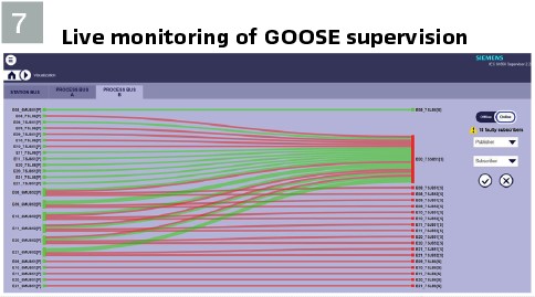
The use of GOOSE supervision (LGOS) and SMV supervision (LSVS) provides these benefits without the need for any custom logic or user intervention during the configuration process. The data objects of these logical nodes can be included in reports to the substation automation system (e.g. RTU and/or HMI) and various third party tools are available to perform live analysis in a substation. Tools such IEC 61850 Supervisor (included with Siemens IEC 61850 System Configurator software and shown in Figure 7) can ensure that GOOSE messages are being published whilst also checking the LGOS statuses at the subscribers to ensure the messages are being received correctly at all destinations. Visual representations provide for a quick overview of the system with the ability to perform further diagnostics if required.
Conclusion: As work on IEC 61850 has progressed, it has incorporated many lessons learnt in the early years of deployment. It is recommended that the latest edition of IEC 61850 be used for all new projects and that the inbuilt test and simulation modes are used. This will lead to a significant reduction in the amount of custom logic required in each IED, thus eliminating both risk and cost for a system. By operating according to the test modes provided in the standard, there will be less of a learning curve for technicians that are new to the system, especially as more people become aware of how the standard test modes work.
Consideration should be given to migrating to digital substation designs, as these generally require less maintenance and incorporate more self-monitoring features. However, they do require a heavier reliance on the test and simulation modes and require a careful design to ensure that all operational maintenance scenarios are possible, including future expansion of the substation.
Biography:

Daniel Abetz has worked in the electrical industry for over 15 years, graduating from Curtin University in 2006 with Computer Science and Electronics & Communications bachelor’s degrees. Initially spending over ten years in project, operational and asset management roles in the utilities division of a mining company, he joined Siemens in 2018. At Siemens he has worked in the protection and automation products team in Australia, giving him experience from the perspectives of both customer and vendor.


