Janos Pattantyus, Denis Francesconi and Jean Raymond, Hydro-Quebec, Canada
Historically, the electricity market was made up of power plants with centralized grid monitoring and control. It was a platform consisting of one-way energy transactions. The arrival of Distributed Energy Resources (DERs) has led to the decentralization of the production and supply of electricity, creating new types of interactions on a two-way network.
These new relationships and transactions, within the general context of the energy transition, are redefining the role of customers, who can now be both producers and consumers-or prosumers-of electricity.
The energy transition brings a variety of challenges for Hydro-Québec’s power generation units, such as production asset sustainability, minimization of the unit cost of production and reduction of operating costs. On the other hand, there is a need to maintain certain basic functions, such as protection, control, and operation, while also allowing them to evolve. To understand these emerging dynamics, a fresh look at the electricity landscape is required. Several factors contribute to the current complexity of the electricity network, in particular:
- Variability and intermittence of renewable production
- Decrease in frequency response capacity and decrease in system inertia
- Modification of load models and unpredictability
- Dynamics of the system becoming both faster and more unexpected
- Need to manage a considerably growing number of production and load points
- Increased risk of cyberattacks on the power grid
Guiding Principles

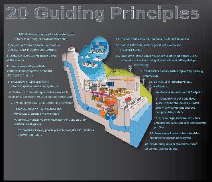
To address these challenges, Hydro-Quebec has developed a new architecture and requirements for its design of future generating stations and hydroelectric developments. The new architecture is based on 20 guiding principles defined a priori, and that can be applied to the entire evolution phase (the Figure on page 38). The vision behind those 20 guiding principles is based on three phases, the first of which includes the following four components (Figure 1).
The first component achieves the sustainability of automation infrastructure by implementing standardized IEC technologies and the IEC 61850 SCL (Substation Command Language) standard. This infrastructure will collect data, reduce cabling, interconnect different components amongst themselves and towards the control system using CIM (Common Information Model). A feature of the future generating station is a close collaboration with a Predictive Monitoring Analytic Center, where the monitoring and management of each generating station will be based on increasing predictive maintenance over corrective and systematic strategies. This approach will support the principle of optimized maintenance executed at the optimal time. The following description illustrates the results of our proof-of-concept activities.
Process Description
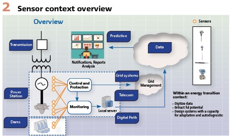
At Hydro-Québec, most of the power we generate comes from water turbines. These machines have several sensors (Figure 2) that are required for protection, control, and condition monitoring. A subset of these sensors (known as hereon instrumentation sensors) measure quantities that related to the mechanical state of each generating unit. The measurements typically include vibration, bearing temperature, oil levels, flows and pressures, cooling water temperatures, hydraulic pressures, stator temperatures, some contacts, etc.
Generally, vibration is measured with eddy current relative movement sensors. These sensors require a specialized electronic device to power and read the signal conditioner and to evaluate signal validity and the vibration signal for the amplitude value.
Temperature is typically measured with three-wire Resistance Temperature Detectors (RTD). These detectors also require a specific electronic interface for the value and validity evaluation. This measurement is common in the industry, and many automation devices are available on the market.
Highway Addressable Remote Transducer (HART) transmitters (4–20 mA) are used for level, pressure and flow measurements. They require the appropriate mA loop electronic interface for power and to evaluate the returned value. The measured values and diagnostic information are also available via the HART communication protocol that rides over the mA signal. Finally, the HART communication interface is also used to configure the transmitters.
Some sensors act as switches, for example a shear pin monitor or a level switch. These are interpreted as digital inputs to the electronic interface that reads them.
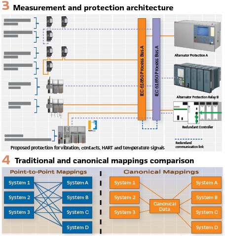
Figure 3 shows the process bus based on the IEC 61850 GOOSE (Generic Object-Oriented Substation Event) protocol. Two Ethernet based process buses provide redundancy.
Some sensors are installed twice to feed each bus. Also, sensors are distributed across the networks in a functional redundant manner.
In addition, two alternator protection relays act in a complementary fashion and are the subscribers to the digitized measurements flowing along the two process buses. Their function is to evaluate received values with respect to trip settings, and then shut down the generating unit as needed.
The controller receives data that enable it to control the generating unit appropriately. It may generate alarms or evaluate parameters for startup, for example. It will also handle the normal startup and shutdown sequences, as well as generate setpoints toward speed and excitation systems, along with other tasks.
Canonical Data Model
The Hydro-Quebec canonical data model is a prerequisite for the successful implementation of future requirements in advanced artificial intelligence and analytics. The canonical data model will reduce the mapping between systems, facilitate the merge between systems and lower the cost of training. It will also streamline the overall management of grid operations by helping to introduce advanced operating services, such as situational awareness and predictive maintenance, and by improving the management of spinning reserves.
The canonical data model as envisioned by Hydro-Quebec entails embedding nomenclature, structures, dictionaries and grammatical rules to data.
The goal of having a canonical data model is to provide a framework for data exchange between systems. This type of framework reduces the mapping between systems and provides a means for merging systems efficiently (Figure 4).
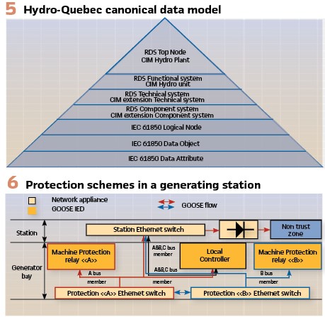
This Hydro-Quebec canonical data model is based on state-of-the-art standards (Figure 5). The high-level data structure is based on utilities’ CIMs (IEC 61970) for power system modeling and energy utility data exchange, including Energy Management System (EMS), topology, wires, and SCADA (Supervisory Control And Data Acquisition).
The end structure is based on IEC 61850 Logical Node data structure. As for nomenclature, at the high level, it is based on the RDS (Reference Designation System) for power systems (ISO/IEC 81346), and at the lower level, on IEC 61850 nomenclature and grammar.
Data Structuring
To transfer the sensor values to the process bus in IEC 61850 GOOSE protocol, Remote Input-Output (RIO) modules from different manufacturers are used. The RIO modules can be configured by the IEC 61850 XML (eXtensible Markup Language) files to different extents.
However, the subscriber clients, such as the protection relays or controllers, must receive the configuration files -also known as ICD (IED Capability Description), CID (Configured IED Description) or IID (Instantiated IED Description) files-in order to be able to interpret the messages.
Therefore, a standardized data model and nomenclature is needed that will be consistent throughout the instrumentation ecosystem.
The first definition is of the data payload itself, which is:
- Mag: the amplitude of the measurement, in floating engineering or Boolean format.
- Q: the quality of the data in 12 bit-string format.
Each GOOSE message includes data groupings known as datasets. Since one of our subscribers limits datasets to 60 items, we will limit a dataset to 20 data items (each with Mag and Q).
The second definition is within the datasets: each signal is assigned a logical node (abstract data object), which is rendered unique by the prefix and instance. The idea behind this is to use the prefix to identify the signal tag and the instance to give an indication of the hardware signal location with the card and channel respectively in the IED (Intelligent Electronic Device) as illustrated in Figure 7.

The next information added is the alarm levels associated with the designated channels. We can define two negative alarms and two positive ones, llLim, lLim, hhLim and hLim respectively.
The full scale of the measurement can also be added as the min and max values. We can see that the definitions are within an SDI (Sub-Data Instantiated) named RangeC.
All this additional information is defined within the Instantiated Data Object (DOI) within the channel.
A number of description information is also added, some as a private statement for the module and channel description, and some as “d” and “dU” values with their respective Instantiated Data Attributes (DAI).
All the parameters we are showing are further defined in the “DataTypeTemplates” area of the XML file.
Bus Configuration & Topology
The instrumentation process bus configuration is a continuation of how Hydro-Quebec applies its protection scheme. In its generator bay, Hydro-Quebec applies an A and B configuration (Figure 6).
The A and B configuration implies that, in its pure form, the machine protection chain is provided by two different manufacturers from the acquisition to the protective relay.
The power supplies are independent and separated by 1.5 metres, in case of environmental issues. In this scheme, A and B have separate VLANs (Virtual Local Area Network).
For example, the A protective relay cannot subscribe to the information provided by the B VLAN. Conversely, the process controller is subscribed to both A and B VLANs for alarm management purposes. PRP (Parallel Redundancy Protocol) and HSR (High-availability Seamless Redundancy) are not used in the generator bay protection scheme. The TCP/IP services are provided by a separate network port and member of a C VLAN. The information is published on the A and B process buses using GOOSE communication with a rate of 100 data objects being published per 100 msec.
The publishing IEDs have one Ethernet port with VLAN tags for GOOSE communication and TCP/IP services. Depending on the bus (A or B), each IED is assigned to the proper Ethernet switch. The A and B Ethernet switches segregate the flow to the subscribed ports, based on the VLAN attribution. Ethernet switches trunk all the LANs (A, B, C) to the station switch. By using GOOSE communication, a secure outbound unidirectional communication through a passive Ethernet diode is possible. Using this technique, IP network segmentation is respected, and the power station operational network is isolated from untrusted networks. However, outbound transfer of data is maintained.
IED Configuration and Reliability
IEC 61850-6 sets up an efficient way to exchange information between configuration tools. By having a uniform file exchange format, it facilitates the extraction of canonical information vital to creating an efficient system tool chain. This efficiency gain is based on the fact that the validations around the ICDs and SCDs validate the canonical nomenclature defined in part 7 of the IEC 61850. The canonical information structure and nomenclature provide a means for Hydro Québec to maintain its existing naming structure and create an information bridge between the existing system and IEC 61850 nomenclature.
To facilitate the tool chain assembly of the ICD file, Hydro-Québec has to apply some derogations from the mandatory requirements in part 7 of the 61850 standard. The use of Beh (Behavior) is dropped and the LNtypes is kept to their smallest form so as not to use unnecessary memory space.
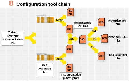
The field IED has ICD templates with a fixed dataset size. The datasets have DOs that can be renamed in accordance with the process tag. The collection of the field ICD is merged into different SCDs in accordance with the final subscriber: Protection A or B or local controller (Figure 8). The ICD validation process is critical, as the schema validation is insufficient for validating the files. Rules for validating the instantiated logical nodes with respect to data types had to be added.
Engineering Tool Chain
The process bus configuration is based on IEC 61850 communication. It is therefore logical to assume that the tooling is based on IEC 61850. However, this is not entirely accurate. Most IED tools are based on the vendor tools, which are not created with IEC 61850 in mind. In many cases, vendors create compatibility by providing a mapping tool to bridge the IEC 61850 world with their IED products that are IEC 61850 enabled.
This leads to a number of challenges. Not only does the vendor tool have its way of mapping signals but Hydro-Québec does too. The path used to circumvent this challenge is created using scripts. The IED environment is emulated by creating input-output signal sheets from which the field IEDs receive their configuration file. The ICDs from the signal sheets are then amalgamated into SCDs compatible with the vendor format for import into their engineering tools.
Benefits
1 – Conventional wiring versus IEC 61850 process bus implementation: The new IEC 61850 based design uses GOOSE messaging instead of point-to-point wiring. The configuration description available in XML files, as defined by the IEC 61850 SCL standard, allows the automation of the test process. This includes the development of the test plan as well as the actual testing. Moving from a conventional architecture to an IEC 61850 based one will lead to significative benefits with regard to the engineering tasks, initial installation and commissioning of the generating station.
Better FAT (Factory Acceptance Test) and faster SAT (Site Acceptance Test) processes can also contribute significantly to the benefits of this new architecture. The FAT and SAT cost reduction could directly lower project management costs by reducing staff overhead and, more importantly, could decrease the duration of the project by cutting SAT lead time by approximatively half.
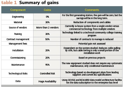
Table 1 summarizes the gains that can be made with this first technological level based on the different components of a project.
2 – Replace time-based maintenance with condition-based maintenance and extend the time-based maintenance schedule: With improved monitoring, enabled by measurements and information that are accessible via a standardized canonical data model and the standardized communications based on IEC 61850, Hydro-Quebec can replace partially time-based maintenance with condition-based maintenance. Combining utility asset management data with the condition and criticality of the generating station assets allows for the prioritization of maintenance to where it will be most effective. Defective generating station assets are identified at an early stage through enhanced monitoring, which allows for the isolation of equipment safely prior to critical failure.
With advanced monitoring, it is assumed that the maintenance time interval of time-based maintenance can be deferred to a year later on some of the tasks, given that the performance parameters are within the specified limits.
The condition-based monitoring will enable the detection of problems with the equipment before they cause a breakdown and require an expensive replacement or repair. Using IEC 61850 as a communication standard, the access to and processing of this information are improved.
3 – Canonical data model: Implementing a canonical data model leads to the following benefits:
- Lower ownership cost from merged systems
- Lower cost in interfacing between systems (local and enterprise)
- Lower cost of training personnel
Other benefits from implementing a canonical data model are linked to the overall management of grid operations. The canonical data model makes it easier to add advanced operating services, such as situational awareness and improved management of turning reserves. Maintenance and predictive maintenance also benefit from easy access to a well-structured data model.
Conclusion
As can be ascertained from this article, substantial engineering efforts were required prior to the field implementation of the forthcoming generating station to set up IEC 61850 process bus and instrumentation close to the data sources. In addition, existing tools and engineering processes had to be re-assessed and adapted.
However, our successful proof-of-concepts demonstrates that the benefits outweigh the cost of the initial extra effort involved.
Biographies:

Janos Pattantyus Has worked for more than 28 years, as rotating equipment specialist in machinery protection, vibration analysis and predictive maintenance. Janos holds a bachelor’s degree in mechanical engineering from McGill and a master’s degree from Ecole Polytechnique. He is certified category 4 in vibration analysis and a licensed engineer in the province on Quebec. He also has more than half a dozen publications to his credit, as well as many presentations. Janos is an active member and leader of the international working group IEC 61850 Dynamics Modelling Joint Task Force. Janos works currently in the instrumentation and mechanical protection systems team within the Hydro-Quebec automation expertise department.

Denis Francesconi is a system matter expert in control systems for Hydro Power Plants with over 30 years cumulated in the Hydro domain of which 24 years with Hydro-Quebec. Denis graduated in 1987 at Montreal’s Concordia University with a bachelor’s degree in electrical engineering and is a licensed engineer in the province of Quebec. He participated in the IEC Technical Committee 57 in extending IEC 61850 to include Logical Nodes required for the Hydroelectric domain.

Jean Raymond has worked for more than 32 years, both as a telecom engineer in several divisions of the company and as an engineer responsible for the evolution and the long-term development of its transmission and electricity generation systems. He has developed considerable expertise in system reliability over the years. Jean holds a bachelor’s degree in electrical engineering from Universite Laval and a master’s degree and a Ph.D. in Electrical Engineering (Telecommunications) from Universite Laval, in collaboration with the Defence Research Establishments. He also has more than a dozen publications to his credit. Jean is an active member of international working groups (IEC, IEEE) and the convener of IEC TC57 AG22 “Prepare for the future.”


