by Christopher Pritchard and Fred Steinhauser, OMICRON electronics, GmbH, Austria
The long-lasting use case for time synchronized distributed testing
Communication aided line protection schemes, sometimes also called teleprotection schemes, were and are applied to protect important assets, in particular high-voltage transmission lines. Thus, the verification of the proper function of these schemes is important. But a thorough assessment of such a scheme cannot be done by just injecting test signals on one end of the line. To stimulate the combined action of the protection devices on both ends and the involved teleprotection equipment, a well-coordinated injection of test signals on both ends is required. Well-coordinated in this context means that the test signals must match the simulated fault condition and the injection must be exactly timed on both ends.
The time synchronization of the fault injection was hardly to achieve before 1990. There were line differential protection devices that synchronized themselves via the communication channel and could provide a synchronized test pulse on both ends as an additional feature. The approximate timing error between these pulses was in the order of one electrical degree of the power system, which, although big compared to today’s standards, would already have been good for many purposes. But for testing distance protection schemes, this was not generally available.
The early days of end-to-end testing (from 1993)
When GPS, as the first deployed GNSS, became available for users outside the U.S. military in the 1990s, the application for the time synchronization of distributed test systems came also into reach.
Early GPS receivers from specialized vendors already generated sync pulses at preset times. These sync pulses were fed to binary inputs on protection test sets to trigger the execution of a test sequence. Tests of this kind were conducted as early as in 1993.
The GPS equipment at that time was entirely independent from the protection testing equipment, using its own power supply and operator interface. Also, the protection test software was not yet a test plan with multiple embedded test sequences that could be executed in a row. Each test sequence was contained in its own test file that had to be opened and set up for execution individually. Of course, these test sequences had to be prepared in advance, as there was no way for an ad-hoc creation of functioning tests. There was also no remote control applied at that time. Both ends had to be operated locally by skilled personnel and the test coordination between the teams at the ends was performed via telephone. The overhead was enormous and considerable time margins for the manual interactions had to be foreseen. Consequently, only a small number of test sequences (shots) could be executed within such a test campaign.
Nevertheless, the in-depth assessment of teleprotection schemes became possible this way.
Improved time synchronized protection testing (from 1999)
During the rapid development of protection test systems and related accessories in the 1990s, GPS receivers became available that are now tightly integrated into the test systems. Such GPS equipment is operated from the test software and it is available as an additional trigger source without the need to establish binary output/input wirings for time synchronization, thus being much more conveniently to use than a decade ago. The “Selective Availability” of GPS was discontinued on May 1, 2000 (in accordance with a law signed by President Bill Clinton). High accuracy positioning and timing was now available for everyone.
Test plans in advanced protection test software did contain multiple embedded test sequences which could be executed in a row, each one with its own time trigger. Still, the test sequences had to be manually prepared in advance to match each other on both ends, which is a cumbersome and error-prone process. Individual instances of the test control software were executed at each end. (Figure 1).
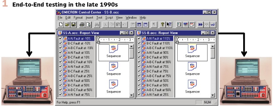
But with remote control, the test coordination could be performed from one “master site”. The need for coordination between test teams via telephone was greatly reduced. The test results still had to be manually collected for the evaluation of test results for the entire protection system.
This method was doable for testing line protection with two terminals. For three-terminal lines, no such field test tests are known, the creation of the test sequences is just too complicated. Likewise, the testing of busbar protection with multiple, time synchronized test sets was not yet feasible (except for trivial cases) because of the complexity of the setup of the test signals.
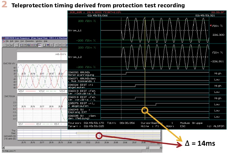
As a by-product on top of assessing the function of the protection scheme as a whole, the measured timings also delivered data about the performance of the teleprotection channel and related equipment. The results showed that the actual figures for the transmission delays were better than the estimated values derived from the worst-case data for the involved components. As these estimated values determined other delays to be configured in the protection devices, options for accelerating the protection schemes were uncovered this way. (Figure 2).
Remote control & power system simulations
Today communication aided protection schemes are the de facto standard in transmission systems and are growing significantly even in distribution systems. Around 2015 novel testing solutions came to the market to address the remaining shortcomings of the existing end-to-end test solutions. The so-called system-based test approach is combining a power system simulation to derive test signals with the possibility to control multiple remotely distributed test sets from one PC and test document instance. This is reducing efforts during preparation, execution and post-execution.
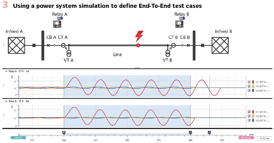
Preparation: As it was mentioned in the previous paragraphs, it can be challenging to prepare well-coordinated test sequences independently for each end. Within a power system simulation (Figure 3), a test case is defined by operating breakers and placing faults. The necessary test signals for each test set at each end are automatically calculated and well-coordinated in one simulation run. Common challenges like different current transformer (CT) ratios at each end are automatically taken care of.
Additionally, testing with signals that are derived from a transient power system simulation can better ensure the correct operation of the protection system. While testing threshold and times of protection elements is important to ensure the correct settings are in place and the relay is operating, it cannot ensure that the system is operating correctly under realistic fault conditions. During a system-based test the whole protection system (consisting of multiple relays) is tested against realistic power system scenarios like faults inside and outside the protected zone. As the system-based end-to-end test is usually performed towards the end of a commissioning it represents a perfect last acceptance test.
Execution: Surely every experience testing engineer can share stories of the hassle involved in running an end-to-end test in the field. The issues range from accidently running test sequences that do not match between ends to assessing overall behavior of the system over separate instances and ends. Most of these issues source in the fact that the control over the test setup is split onto multiple PCs and instances. The way to improve this was obvious – one PC and test document instance to control the whole test setup.
When the execute button is pressed, the system-based test software calculates the test signals with a transient power system simulation for each end and uploads these signals to each time-synchronized test set. Automatically the same absolute start time is set and when this trigger is reached a well-coordinated injection will start. After the injection is complete, the binary response of the relay is automatically sent back to the controlling PC where an automatic assessment is performed.
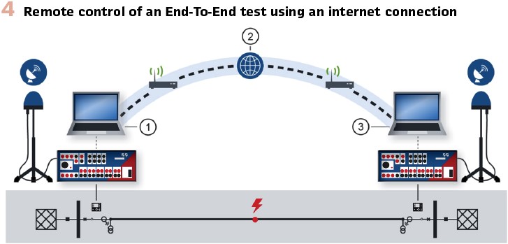
To make this possible, the controlling PC has to communicate to each test set. Apart from a direct connection for example via a wide area network (WAN) or a direct fiber between substation, a simple Internet connection can be used (Figure 4). To use an internet connection, each end requires a PC with an internet connection directly connected to the local test sets. The PC will grant remote access via a cloud service to the central PC that is running the test document. This way the whole test setup is still controlled from one PC and test document instance. Similar to a single relay test, one test step or multiple test steps can be executed with one button press. The response of each end is available for assessments immediately after execution.
It is part of every field tester’s life that test cases are failing, either because of errors in the test setup or protection system; you can even call it the purpose of testing. Because the power system simulation is still part of the test document in the field, it enables the tester to make necessary changes to the test cases during troubleshooting.
Right after the field test is concluded successfully, one single report can be generated from the single instance test document, avoiding the hassle of merging separate reports from each end separately.
Evolution of Time Synchronization
As mentioned in previous paragraphs, time synchronization of test sets is necessary to avoid unwanted phase shifts between the outputs of the different test sets. The common way, as already described, is to use dedicated GNSS antennas, which need to be placed outside with sufficient distance to buildings and are connected to the test set. Apart from increasing the setup effort, this method has its limitation when the path outside is longer than the maximum antenna cable length or the surrounding Infrastructure (e.g. high rise buildings) limit the GNSS signal reception.
Another option is to use the existing timing infrastructure within the substation, which is used to time synchronize the IEDs. In the past this was often achieved using IRIG-B. The downside of IRIG-B is that it requires special HW and cables and that the absolute time stamp is configurable. It is a common activity that is wasting precious time to figure out if the absolute time stamp in one substation is the same as in the other substation.
A better time source in substations is IEEE 1588 precision time protocol (PTP), which is nowadays the de-facto standard for Digital Substations. The benefit is that it is an Ethernet based protocol, which runs via the same Ethernet infrastructure as the Sampled Values (SV) and GOOSE messages. The test may either obtain the precision time via the same Ethernet cable from the substation network or alternatively from its dedicated GPS-disciplined PTP clock. A copper Ethernet cable can be as long as 100 m, thus eliminating many reach issues.
Testing non-distributed multi-IED Schemes
We already mentioned that a system-based end-to-end tests are a perfect final acceptance test to make sure the protection system is actually operating as expected for realistic power system conditions. This is due to using a power system simulation to derive realistic test signals and because we are testing a system of IEDs including the communication instead of a single IED reaction.
This benefit equally applies to protection schemes within one substation. One example can be busbar protection scheme – either bus differential or fast-bus schemes. In such a case multiple test sets can inject into different field unit IEDs. All test sets are still controlled from one test document instance which show the busbar topology. All necessary breaker and disconnector statuses are automatically set according to this topology. If supported by the test set, they can even act as PTP master, making an external time source unnecessary. Finally, when the scheme only operates on SV streams, the whole setup effort is reduced to plugging in an Ethernet connector.
Taking advantage of standardized communication protocols
Newest implementations of teleprotection schemes use IEC 61850 GOOSE messages for exchanging information. Time synchronized communication test devices for capturing and assessing Ethernet traffic measure the occurrences of these GOOSE messages at the involved locations and even deliver statistics for the propagation delays in each direction derived from a large number of measurements to assess the telecommunication channel as such. This also introduces an entirely new view on the dependencies. While the teleprotection equipment was a dedicated addition to the protection devices to enhance the performance of the scheme, the communication channels are now a part of a communication infrastructure that provides options for all kinds of services, not only teleprotection. This infrastructure needs to be assessed on its own to evaluate its usability for the services that make use of it.
Testing the communication infrastructure and time synchronization: The services in modern PAC systems heavily depend on the availability and performance of the communication infrastructure. Distributed functions like communication-aided protection schemes or busbar protection also require an accurate time synchronization of the involved IEDs exchanging information. Thus, the communication infrastructure deserves or even requires not only a dedicated engineering, but also dedicated commissioning and testing independent of the functions that run on top of it. At this level of sophistication, the communication network is no longer a side topic that can put in operation while the PAC system is brought to life. The communication system must be commissioned first, to be readily available as dependable infrastructure for the PAC system to be deployed.
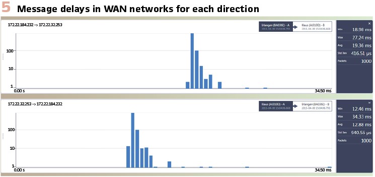
For assessing the communication links used for wide area protection schemes, a distributed measurement system with capturing devices in all involved locations must be used. The capturing devices must themselves be accurately time synchronized, which is also achieved with dedicated GPS receivers if no other trusted time source is available. From the data packets captured in the different locations, the propagation times over the various links are evaluated. The traffic can come from arbitrary sources used just for communication testing, as the network does not care about the content of the data packets and if they are carrying protection related information or not. Thus, the tests can easily be performed at traffic loads that represent worst case scenarios and with a high number of packets involved, dependable statistics can be derived. (Figure 5).
With the capturing devices being time synchronized to their own traceable time source (e.g., the dedicated GPS clock), it is also possible to assess the time synchronization of the IEDs in the PAC system. The synchronization status of merging units can be easily deduced from observing the published Sampled Values streams. By observing GOOSE messages coming from time synchronized protection IEDs, similar assessments can be made. With the right tools, these are simple and pragmatic checks that do not require to go into the specifics of the precision time protocol, unless debugging of the time synchronization is required.
Protection testing protection schemes with standardized communication: Ideally the protection testing takes place after the communication infrastructure and time synchronization has been tested and commissioned. Nevertheless, there is a functional dependency between the communication and protection scheme, which still requires a system test of both components together.
By subscribing to the GOOSE or R-GOOSE message of the communication channel at all ends we now have a kind of x-ray into the scheme, which is extremely valuable when troubleshooting becomes necessary. Because the described system-based testing solution brings all signals into one test document instance, we can for example measure the time between the state changes at each end and even define assessment criteria.
Let’s take a permissive overreaching transfer tripping (POTT) scheme and look at some test cases:
- Weak infeed: It is not uncommon especially for multi terminal lines that one infeed is weak. During a fault the fault current is mainly provided by the strong infeeds, causing the IED at the weak end not to pick up. To cope with this situation the weak infeed logic will still issue a trip when a permissive signal is received, and the voltage drops below a specified threshold. The simulation in the system-based testing solution will simulate the weak infeed and a fault, which will automatically simulate a dropping voltage. If all IEDs trip instantaneously, the test is passed.
- Echo: Echo logic is a special case of a weak infeed. When one terminal of a line is open, detected via the auxiliary breaker contacts (52 a/b), the permissive signal is echoed back to the other terminal, as the fault cannot be beyond the open point and therefore must be within. In the system-based testing solution we just open a breaker and simulate a fault close to the open breaker, in zone 2 for the feeding IED. When the feeding side still trips instantaneously the test is passed.
- Reverse blocking: It is a necessary logic when POTT schemes are applied on parallel lines. A fault on the parallel line is seen by one IED in forward and the other IED in reverse direction (a non-accelerated tripping condition). When one terminal of the faulted line correctly trips, the fault current can reverse in direction. The IED on the non-faulted line that saw the fault in reverse direction now sees the fault in forward direction while the permissive signal is still present from the system condition prior to the trip, which causes an accidently trip. This issue mainly caused by the latency of the communication channel. It is a perfect example why a POTT scheme must be tested with the real communication channel in place. The test is passed when the scheme under test does not trip and remain stable.
Because the communication channel is standardized it is also possible to test only one end and simulate the permissive signal, which makes it possible to investigate the logic under different time delays. This can make sense in the laboratory, but will not replace an end-to-end test, as it is not testing the behavior under the realistic time delays etc.
Biographies:

Christopher Pritchard Dipl.-Ing. (FH) was born in Dortmund / Germany. He started his career in power as an electrical energy technician. Christopher received a diploma in Electrical Engineering at the University of Applied Science in Dortmund in 2006. He joined OMICRON electronics in 2006 where he worked in application software development in the field of testing solutions for protection and measurement systems and is now the responsible Product Manager for system-based testing solutions.

Fred Steinhauser studied Electrical Engineering at the Vienna University of Technology, where he obtained his diploma in 1986 and received a Dr. of Technical Sciences in 1991. He joined OMICRON and worked on several aspects of testing power system protection. Since 2000 he worked as a product manager with a focus on power utility communication. Since 2014 he is active within the Power Utility Communication business of OMICRON, focusing on Digital Substations and serving as an IEC 61850 expert. Fred is a member of WG10 in the TC57 of the IEC and contributes to IEC 61850. He is one of the main authors of the UCA Implementation Guideline for Sampled Values (9-2LE). Within TC95, he contributes to IEC 61850 related topics. As a member of CIGRÉ he is active within the scope of SC D2 and SC B5. He also contributed to the synchrophasor standard IEEE C37.118.