History of Earth Fault Detection in the 1930s, Earth Fault Compensation
by Walter Schossig, Germany, and Thomas Schossig, OMICRON electronics GmbH, Austria
As already the decade before the 1930s have been filled with innovations, field tests, and progress. We had to select the topics for this article, which finalizes the history of earth faults. We are going to start in Germany once more.
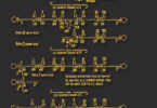
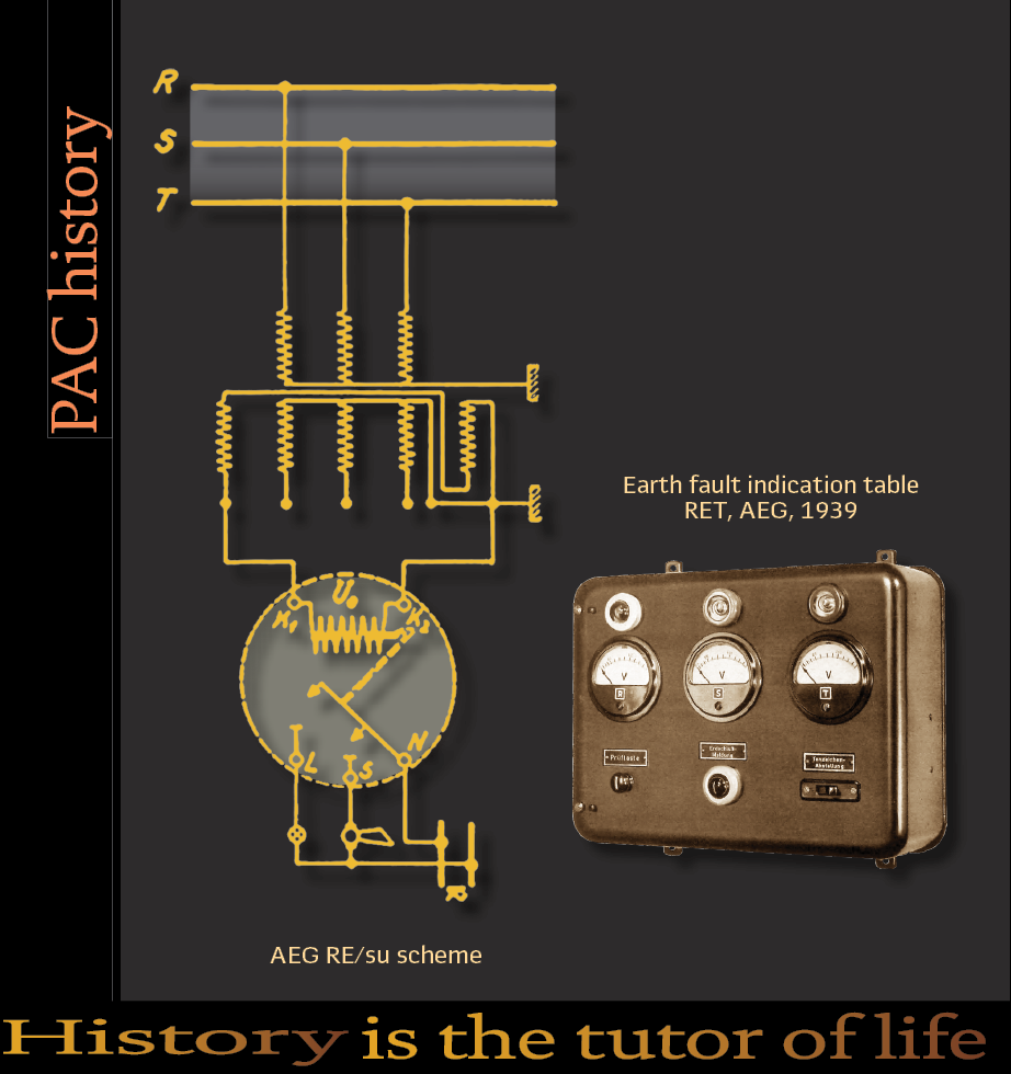
Very typical in Germany for the late 1920s/ early 1930s were AEG’s earth fault indication relays RE. These single-phase devices indicated the earth fault clearly. Based on the signal relay R/s (1926) different variants were available: (Figure 1).
RE/su with voltage winding (U>, nominal voltage 110 V), also available as modified variant for compensated grids. Figure 1(a, b, c.)
RE/si with current winding (I>) for isolated grids, nominal current 5A
The device was renamed to REA in 1935. The startup time was two periods, the weight of every device 1.2 kg.
Experience has shown that the line-to-earth voltmeter—or Uo voltage indicator-was very frequently overlooked by operating personnel. In the case of the RE/su earth-fault signaling relay, a rotatable disc is divided into three sectors. Magnetic and mechanical locking mechanisms position the disc in three distinct states.
Upon the occurrence of an earth fault, the white disc becomes visible; after acknowledgment, the indicator dot disappears, while the white disc remains visible until the earth fault is no longer present.
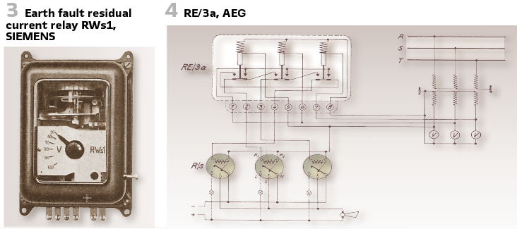
The RE/3a earth-fault indicator relay by AEG (see Figure4) utilizes the voltage rise of the two healthy phases relative to earth to signal simple earth faults. It consists of three voltage relays connected in a star configuration; however, under normal operating conditions, their armatures remain unenergized.
In the event of an earth fault, the voltage relays corresponding to the healthy phases receive an elevated voltage, causing their armatures to pick up and thereby actuate their contacts.
The devices mentioned indicated an earth fault. If it is requested, to detect the section affected by the fault and to switch off, watt metric earth fault relays were used. Connected to the star point of the 3 current transformers, it has to be differentiated if the grid comes with or without compensation of the earth current. If there is no compensation, the entire earth current, also fed by the other phases, through the fault position, back to the faulty line. The current can be, especially in bigger grids, high. Watt metric relays, connected to the earth current and the earth voltage allow direction dependent choice. Timing elements could be added and allowed grading. The summarized earth fault current is almost pure capacitive. So, the relays must implement the sin φ scheme. Typical example is RbW1, by SIEMENS (Figure 2).
In compensated grids there is no need to switch off the feeder, an indication is sufficient, as shown in Figure 2.
If the trip is required, with additional timing elements (RW1 and Rs1) time grading was possible. Bigger cable networks might demand tripping, since earth faults could develop into a short circuit. Mashed networks could be protected by Earth fault protection with residual current relay RWs1 (Figure 3).
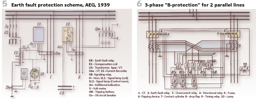
AEG published in 1939 its own book on earth fault protection. Explaining physics, possibilities, and implementation examples (Figure 5).
The standard book for selective protection in the 1930s was published by Rüdenberg.
He described “8-protection” (“Achterschutz”), for 2 parallel lines with tripping in case of earth fault (Figure 6).
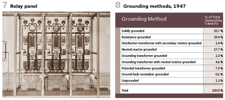
The back of an implementation is shown in Figure 7.
Also, in the US trials with Petersen coils were reported in the early 1930s, for example in the 11-kV-grid of Edmundson Electricity Corporation.
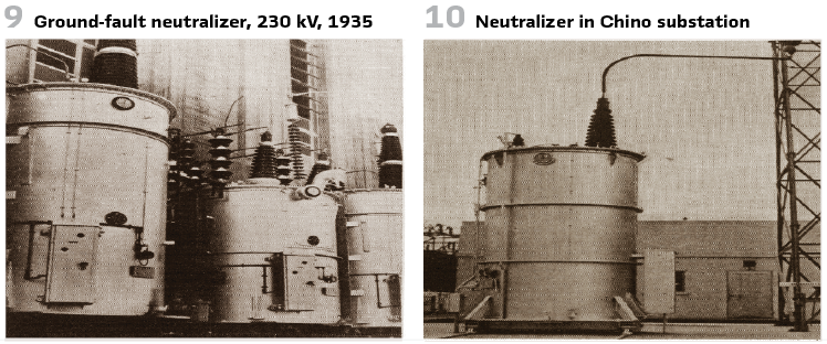
AIEE published it is “Report on Present Day Practices in Grounding of Transmission Systems” for the first time in 1923. The second report was published in 1931. The third report will appear in 1947 and showing the grounding methods in the US and Canada at this time (Figure 8).
Victoria Fall & Transvaal Co. in South Africa shared positive experiences in the 40- and 80-kV grid.
What is the compensation limit? Meyer, G. specifies an extinction limit of 30 A to 40 A for capacitive or inductive residual currents and determines that the duration of ground-fault arcs increases approximately quadratically with the residual ground-fault current, starting from 0.2 seconds. On the 2nd of April in 1931 Wideröe files his patent DRP 569159 for the selective indication or disconnection of an earth fault.
Earth fault protection is not only important for transmission lines, but also generators. Stator earth fault protection was under investigation in the USSR in the 1930s, since earth faults are the biggest damage for rotating machines. That is why it is important to detect stator earth faults. The generator must be switched off, to avoid scorching the iron which causes massive maintenance work. The investigation on this protection with its first period took place between 1933 and 1945.
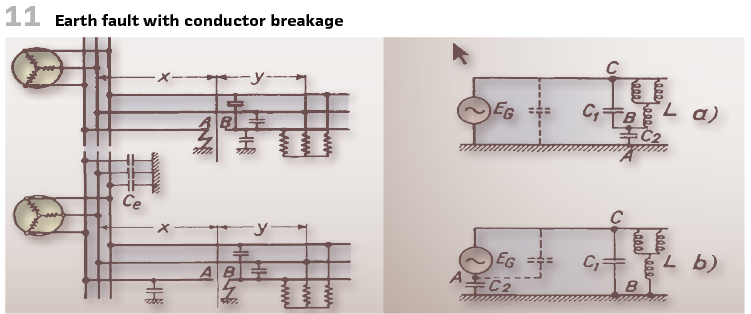
The generators were equipped with power direction relays. Stator earth fault protection should trip. To do this, artificial earth fault currents were created for 2 reasons. The first was, to achieve the sensibility of earth fault protection. The second was to decrease the overvoltage, caused intermittent arc short circuits. The commissioning of the largest ground-fault coil and the one designed for the highest voltage (230 kV) by GE in the USA (and presumably worldwide) at Boulder Dam, California Edison Co. (US) took place in 1935. Figure 9 shows the coils (100/135 A or 200/270 A), 50 cycles.

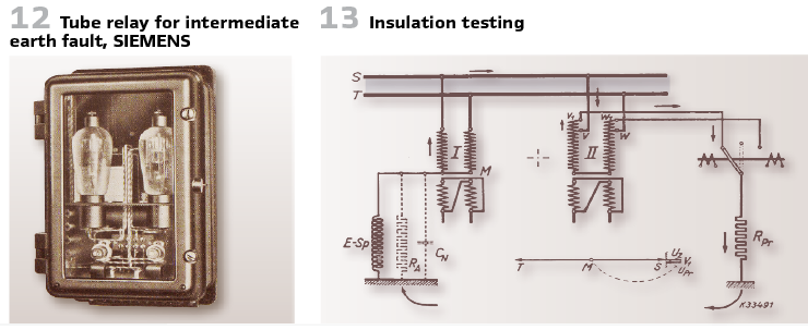
A ground fault occurring in conjunction with a line break warrants particular attention. Figure (11a) illustrates the ground fault on the supply side, while Figure (11b) depicts the indirect or so-called “inverted-ground fault. Figure 11 shows the earth fault on the feed point side (a)) or inverted (b).
It is interesting to see that already in 1936 Bauch published his paper on travelling wave in case of earth faults.
Earth faults are important all the time for the grid operation. Earth faults are the most happening faults in the grids. Every earth fault has an impact on the assets and damages them.
The entire topic of insulation monitoring is related to this since earth faults damage the insulation.
It was in 1936, when Schaubert proposes a network test involving a neutral-point-to-earth voltage of various phase angles and normal power frequency, as well as the simulation of an earth fault.
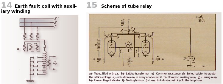
Figure 13 shows the insulation testing in 2-phase grids and the elimination of the residual current in case of earth fault. In some cable grids earth faults appear as wipers, intermediate faults. Figure 12 shows a realization with a tube- so electronics entered the substation for the first time. The scheme is shown in Figure 15.
To give an overview on the status of earth fault protection in the second half of the 1930s, a look into the German magazine “Elektrotechnische Zeitung” helps. In the section “for the young engineer” Hans Titze from Berlin described the state of the art and explained the schemes used at this time (1937).
At first, he explained how the earth fault voltage can be measured.
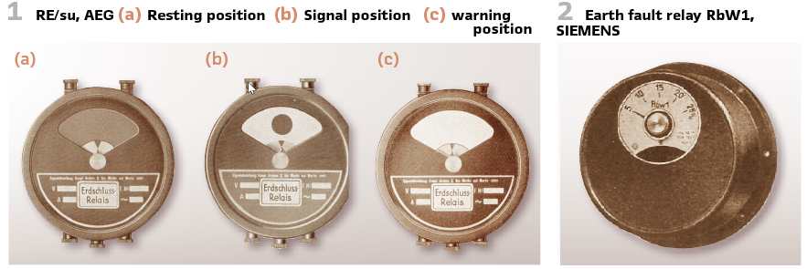
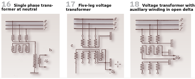
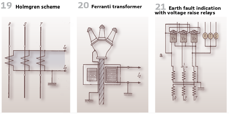
Figure 14, Figure 16, Figure 17, and Figure 18 illustrate the methods. Of course, in addition the current needs to be measured .The zero current can be derived by summing the currents electrically (Figure 19) or magnetically (Figure 20).
As already described, indicating discs showed an earth fault. If it is of interest to identify the phase affected three overvoltage relays were used, connected between phase and ground (Piloty relay, Figure 21). The relays will start up when the voltage reaches the phase-to-phase value. This means that only 2 relays will start up. The indicating relays on the right-hand side show the phase affected.
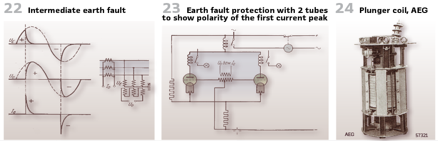
In case of an intermediate earth fault (Figure 22), the relays will not start up. The mechanical relays have been too slow. To solve this problem, again electronics with tubes were used for the first time (Figure 23).
Petersen coils were widely used at this time. Public Service Company, Colorado (USA) performed tests in the 100-kV grid in 1937. In the same year, M.Tayler and P.F.Striz showed in London that more than 50 grids in England are protected by earth fault coils. In 1939 the 66-kV-grid of Metropolitan Edison Company in the US was protected by Petersen coils. To improve the application of the coils, AEG started the development of stepless plunger coils in 1938.

The war interrupted the development and could start again in the 1950s.
Figure 24 shows an example (20 kV, 500 kVA, control range 1…8). Earth faults cause interferences with phone lines, railway signals, radio broadcast.
An arbitration body was implemented in Germany in 1939 to clarify interferences between German rail (Reichsbahn,) utilities, and postal services ( Reichspost), It was called SfB Schiedsstelle für Beeinflussungsfragen.
At the end of the decade, Walther Bender publicized the patent 722348 for “Insulation Monitoring and Earth Fault Indication Devices for Three-Phase Systems”.
Since then, he has been regarded as the “father of active insulation monitoring.”
This concludes the article on earth fault protection in the 1930s. Unfortunately, it does not only conclude this article, but the entire series of articles on history that has been published since the very first issue of PAC World in 2007.
info@walter-schossig.de www.walter-schossig.de
thomas.schossig@omicronenergy.com
Biographies:
Walter Schossig
(1941 – 2026)
Walter Schossig (VDE) was born in Arnsdorf (now Czech Republic). He studied electrical engineering in Zittau (Germany), and joined a utility in the former Eastern Germany. After the German reunion the utility was renamed as TEAG, Thueringer Energie AG in Erfurt. There he received his Masters degree and worked as a protection engineer until his retirement. He was a member of many study groups and associations. He is an active member of the working group “Medium Voltage Relaying” at the German VDE. He is the author of several papers, guidelines and the book “Netzschutztechnik
[Power System Protection]”. He worked all of his life on a chronicle about the history of electricity supply, with emphasis on protection and control. He passed away while working on this article.Thomas Schossig (IEEE) received his masters degree in Electrical Engineering at the Technical University of Ilmenau (Germany) in 1998. He worked as a project engineer for control systems and as a team leader for protective relaying at VA TECH SAT in Germany from 1998 until 2005.
In 2006 he joined OMICRON as a product manager for substation communication products. He is now responsible for the business area Power Utility Communication at OMICRON. He is author of several papers and a member of standardization WGs.