by Walter Schossig, Germany, and Thomas Schossig, OMICRON electronics GmbH, Austria
Ground fault protection for networks with ungrounded or high impedance-grounded star points did not yet exist. More methods for ground fault detection were developed, allowing for the detection and disconnection of the fault location through switching operations. Initially, ground faults were only detected by voltage displacement. Due to the low currents, there was usually sufficient time to find the fault location and then disconnect it from the network
The story of Rühle deserves mention here. While still employed at the Rheinfelden (Germany) power plant before the First World War, he would walk the power lines with a dog, and when the dog barked, he knew he had found the ground fault location. Animals are more sensitive to electrical voltages than humans due to their four-legged nature. It is also known from the low-voltage local grid that horse-drawn carriages would break down while galloping due to an insulator defect. Simple ground fault indicator relays were required to detect ground faults.
Figure 1 shows an insulation tester from Hartmann & Braun (H&B) in Germany in the year 1900. Figure 2 shows the scheme. The lever visible on the right is first set to the “+” position. The single-pole insulated device is thus connected to the line. Then, it is switched to the “-” position. If the pointer moves only in one position, the deflection corresponds to the fault resistance of the other conductor. If the pointer is at 5MOhm in the “+” position and remains at rest (infinite) in the “-” position, the fault resistance of the negative conductor is 5MOhm, while that of the positive conductor is comparatively high.
At the annual exhibition of the electrotechnical society in Berlin an earth fault indicator for 3-phase current was presented in 1902 (Figure 3).
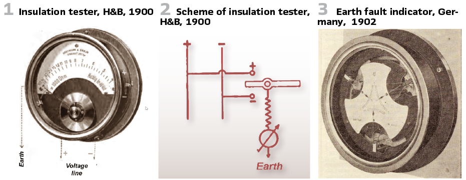
The device featured magnetic damping and consisted of three metal plates. Double plates with pointers rotated between them. The fixed plates were connected to the three-phase system, while the movable plates received the ground fault. The value of the ground fault could be determined from the movement of the pointer.
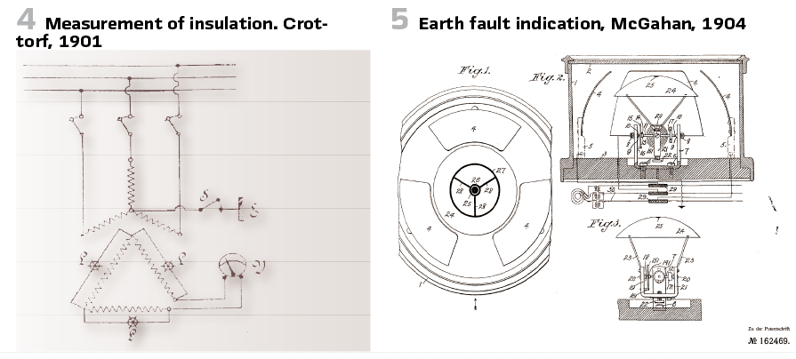
In the US it was Paul McGahan of Westinghouse in Pittsburg who submitted his patent in 1904. It was an electrostatic device with one segment for each phase. Between the phase was a moveable line which indicates earth fault (Figure 5).
At the Crottorf (Germany) overland power station, a special small switchboard is provided for insulation measurements. The circuit used is shown in Figure 4. The high-voltage lines lead to a small three-phase transformer, whose phases are primarily connected in a star connection, while the neutral point can be connected to ground using a changeover switch. The secondary coils are connected in a delta connection, with one corner of the triangle cut open. A lamp is connected parallel to each phase, while a voltmeter is connected between the two phases leading to the open point of the delta. The neutral point of the primary winding is usually ungrounded. If an insulation measurement is to be performed, it is connected to ground using switch S. If a ground fault occurs on any phase, the corresponding lamp in the secondary circuit lights up dark, while the appropriately calibrated voltmeter simultaneously indicates the magnitude of the ground fault. Current measurements on the main switchboard then further determine the supply area in which the fault lies.
Also in the UK at IEE isolation testing was a topic. It was in Birmingham when W.E. Groves presented a scheme for line testing in 3-phase low voltage grids in 1904. The neutral wire was grounded with 2 Ohms (Figure 6).
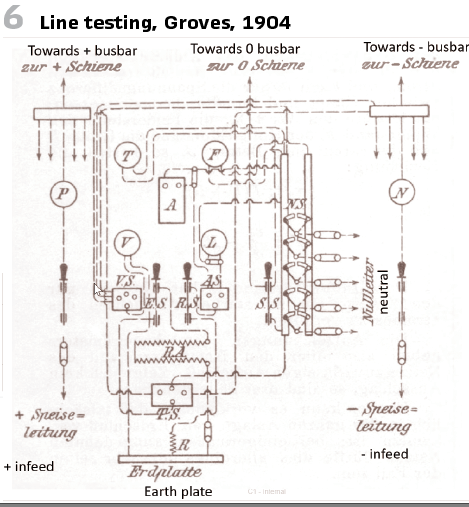
If a ground fault is detected in the system, each distribution section is isolated from the others in turn to determine whether that section is the culprit. One of the following methods can then be used for the investigation:
a) Observe the recording ammeter, which permanently connects the neutral conductor to earth.
b) Measure the insulation resistance using the Russell method.
c) Determine the polarity of the fault location by earthing a phase conductor and observing the ammeters in the main feeder lines.
d) Determine the faulty line by individual testing.
e) Do the same by switching.
f) Do the same by switching off.
g) Final determination using the induction method.
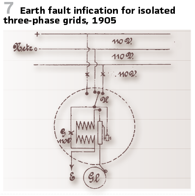
A circuit proposed in 1905 for the optical and acoustic indication of whether there is an earth fault in a three-wire network with an isolated neutral point is shown in Figure 7. Within a housing closed at the front with a glass pane are a light bulb G for mains voltage, an electromagnet, in front of which is a spring-loaded armature with a current breaker for the magnetic coil; on the armature is a clapper for actuating the bell Gl. The magnetic coil and light bulb are connected in parallel. A changeover switch U establishes the connection to the mains. If, for example, there is an earth fault in the + position, then in the – position the upstream and the appliance lamp light up and the bell rings; in the O-position only the appliance lamp and – no lamp.
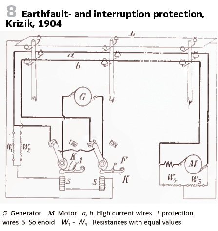
On 8 February 1904, Frantisek Kizik, Prague, presented a protective device for detecting earth faults and interruptions at the meeting of the committee for the founding of the “Austrian Association of Electricity Companies” (Figure 8).
The circuit is completely identical to that of a Wheatstone bridge. Therefore, solenoid S is de-energized during regular operation, but immediately receives a current if, for example, one of the main wires a or b breaks, or if contact occurs between wires L and one of the main wires. In automaton A, the latch K is held by spring F and triggered by solenoid S.
Work was also carried out on improving remote transmission with direct current. However, the machines in the power plants and at the consumers’ premises could only be built to operate safely at limited voltage values. René Thury therefore developed his own system in 1905. (Figure 9 ).
All machines, both generators and motors, were operated in series and equipped with the same switch, namely a changeover switch. Apart from it, each machine only contains an ammeter and a voltmeter, the motors an automatic short-circuiting device. In the power transmission system from Moutiers to Lyon, which was put into operation in 1906,
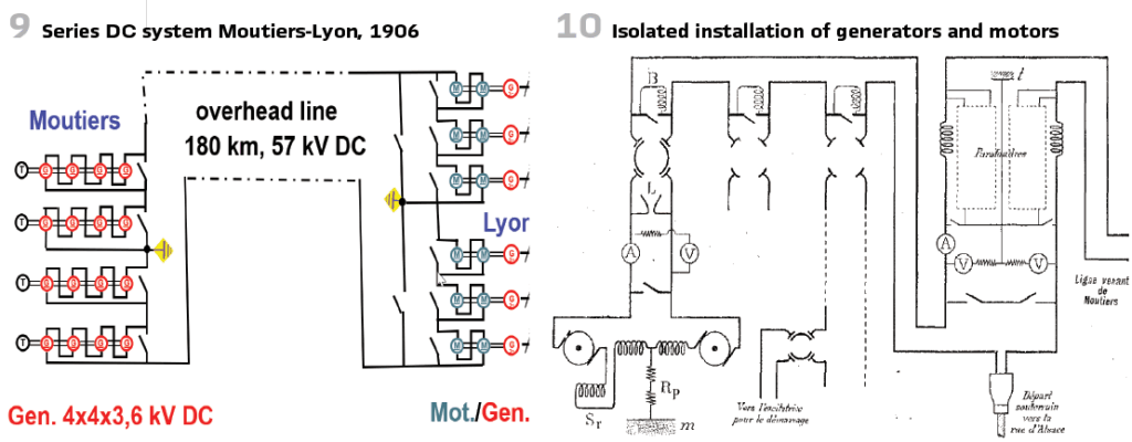
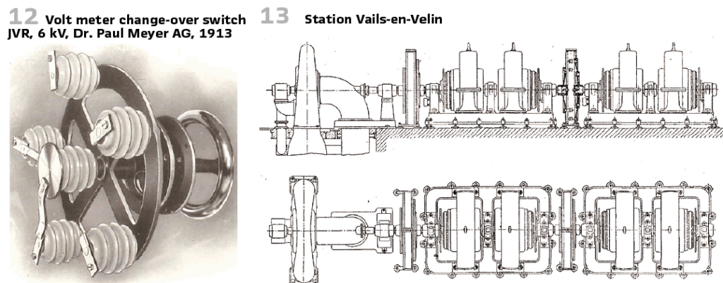
Four groups of machines were installed in the power plant on double-bell insulators made of porcelain (Figure 10), each of which consists of a 1670 hp turbine with four DC generators directly coupled to porcelain for 3500 V, 73 A each. Originally, it was intended to use the earth as a return conductor, but this plan was abandoned, although the relevant tests had been favorable. The earth is now only used to limit the voltage and for this purpose the center of the system in the power plant is earthed. When using a two-pole transmission line with grounding of the center of the system, there were no higher costs than with a single-pole transmission line and return line due to the lower insulation against earth. Another advantage of this arrangement is that the earth offers a certain reserve in the event of a line defect. In order to be able to make the relevant connections, the two switches are provided in the substation. If the earth return line is used, of course, only half of the generator power can be used. A faulty machine could never be disconnected. It was simply short-circuited. Figure 13 shows in the station Vails-en-Velin the voltage meters built into the outgoing feeder in plus or minus against earth, with which the earth fault monitoring is carried out.
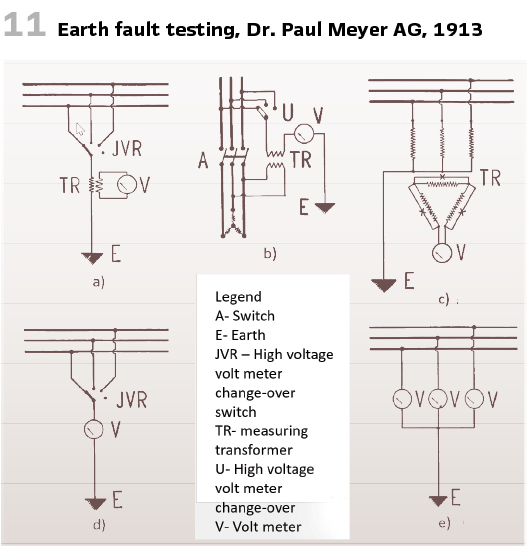
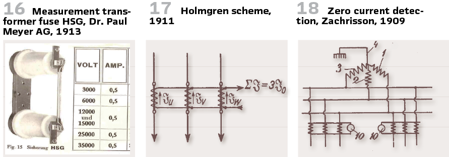
A range of products manufactured by Dr. Paul Meyer AG for ground fault testing is shown in Figure 11. To check the lines for ground faults, a soft iron voltmeter can be used, which is connected in conjunction with a voltage transformer a) and b) or a measuring transformer c) or static voltmeters can be used (Figure 11).
a) Test with electromagnetic voltmeter and voltmeter switch JVR (Figure 12).
b) Test in the de-energized state
c) Test with electromagnetic voltmeter and three-phase transformer with cut-open corner point and three lamp sockets or the electromagnetic voltage meters. The primary side of the transformer is expediently secured by HSG measuring transformer fuses (Figure 16)
d) Test with static voltmeter and voltmeter switch JVR
e) Test with three static voltmeters
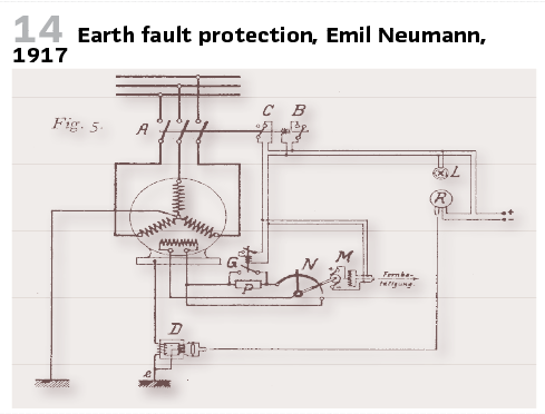
The earth fault voltage was initially obtained by measuring the voltage between ungrounded star points or housings and earth. In 1917, Emil Neumann proposed to use a resistor, choke coil or current transformer (Figure 14).
The arrangement with a delta connection (Figure 19) was already described in the “ETZ” in 1901 and was apparently not considered patentable by the designer. In 1905, the fourth circuit with two star-shaped systems, indicated on the right, was patented.
Based on the grant documents, it can be assumed that the patent office was not aware of arrangement 3 from the “ETZ” because otherwise this arrangement would have been mentioned in the files and the claim for protection would have had to be formulated differently.
But even if this arrangement 3 had not been known, arrangement 2 is completely identical to arrangement 4, so that a patentable idea can no longer be found in it. Once such a patent is granted, one can never know how far one may go with one’s designs and where the patent begins, and the judge, who may have to interpret the patent in disputes, will know even less about this than the designer.
The measurement of the earth fault current already brings us closer to a selective detection of the earth fault. For its measurement, a summation circuit was developed, which sums the currents of all phases so that only the zero-sequence current flows. The Holmgren circuit, used by Torsten Holmgren in Trollhatan in 1911, is well known (Figure 17).
A directional earth fault relay serves as line protection, the moving coil of which is excited by the zero current generated thereby and the zero voltage generated by a voltage transformer connected to the star point of the transformer.
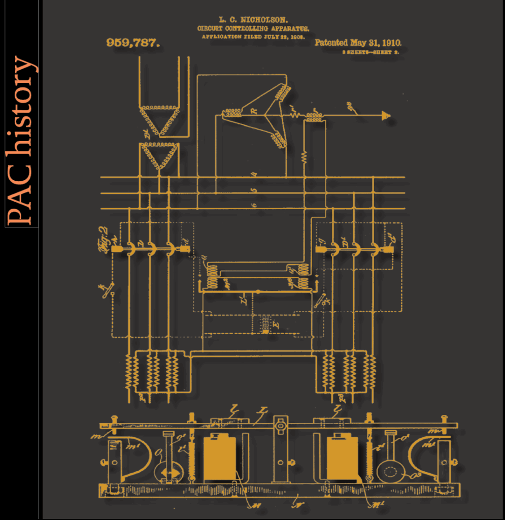
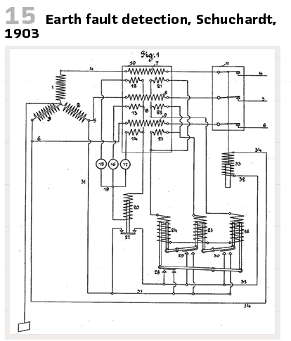
Actually it was Schuchardt with the patent DE160069 (Figure 15) and L. C. Nicholson, who had already filed a patent in America in 1908 (see title page), in 1909 E. Zachrisson filed his patent 30594 in Sweden (Figure 18).
Since faults on overhead lines, in particular, only become apparent when measurements are taken at operating voltage they usually only occur at this voltage, as an arc causes the fault—L.C. Nicholson introduced a fault location method based on a diagram in the Inst. of Electr. Eng. in 1907. From the control center, the current is sent to the fault location via two paths, and the fault location is determined from the readings of two ammeters (Figure 20).
The neutral point of the system is permanently connected to earth. All insulation supports are also earthed. To limit the current, a resistor R is connected, which is initially short-circuited with fuse G. Concrete cylinders with a length of 3.7 m and a cross-section of 0.1 m² are recommended as resistors. With a resistance of 2000 ohms and a negative temperature coefficient, a current between 50 and 100 A has proven suitable for the measurement.
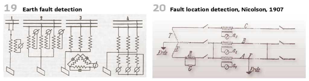
The current flowing through resistor R is split into two parts along paths A and B, which are initially short-circuited by a simple device. The current strength in these parts depends on the impedance values at the fault location F. This allows the fault location to be determined.
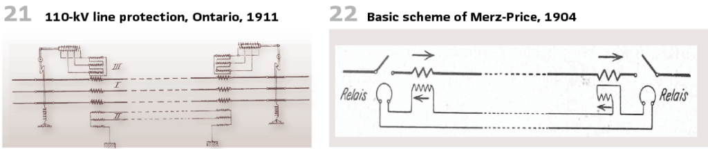
In 1910, the star point of the 110 kV grid in Ontario (Canada) was not grounded. But in April 1911 they decided for an equipment: a water resistance, consisting of 12 buckets made of porcelain. The electrodes in the buckets are connected in series and connected to earth. With the amount of water 15000 kW could be held for 90 seconds.
Line protection was important for short circuits as well as earth fault (Figure 21).
There are measurement transformers used. In addition to secondary windings (II), transformers also have tertiary windings (III). They are connected in star or delta configurations. The secondary windings are short-circuited by special rods and connected to ground. The resistance of the rods should not exceed 200 ohms.
The current is proportional to the primary current. Only a small field develops in the iron cores of the transformers. It is smallest when the currents in the primary windings are equal. This changes when a line breaks.
Considerable electromotive forces build up in the tertiary coils, and large currents arise in the breaker circuits. The oil switches at both ends of the line are pulled out.
The patent by Englishmen Charles Hestermann Merz and Bernhard Price (Figure 22), found its first major application in 1906 and 1907 in the 20 kV cable network of the County of Durham Electrical Power Distribution Co. in northern England.
In Germany, AEG took over the development of the invention, with the first applications being at the Heinitz mine near Luisenthal (Saar) and at the Westfalen power station. A detailed description of the development of differential protection appeared in this magazine in the summer of 2008 and subsequent issues.
The further development of earth fault protection and star point treatment will be discussed in the following articles.
info@walter-schossig.de www.walter-schossig.de
thomas.schossig@omicronenergy.com
Biographies:

Walter Schossig (VDE) was born in Arnsdorf (now Czech Republic) in 1941. He studied electrical engineering in Zittau (Germany) and joined a utility in the former Eastern Germany. After the German reunion the utility was renamed as TEAG, Thueringer Energie AG in Erfurt. There he received his master’s degree and worked as a protection engineer until his retirement. He was a member of many study groups and associations. He is an active member of the working group “Medium Voltage Relaying” at the German VDE. He is the author of several papers, guidelines and the book “Netzschutztechnik
[Power System Protection]”. He works on a chronicle about the history of electricity supply, with emphasis on protection and control.
Thomas Schossig (IEEE) received his master’s degree in electrical engineering at the Technical University of Ilmenau (Germany) in 1998. He worked as a project engineer for control systems and as a team leader for protective relaying at VA TECH SAT in Germany from 1998 until 2005.
In 2006 he joined OMICRON as a product manager for substation communication products. He is author of several papers and a member of standardization WGs.