by Walter Schossig, Germany, and Thomas Schossig, OMICRON electronics GmbH, Austria

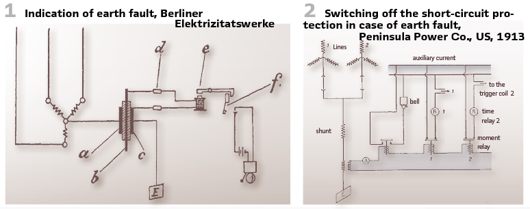
As described in previous articles, in most countries, such as the USA and England, the neutral point of generators and transformers is grounded. In Germany, however, this was prohibited by the postal administration due to the postal telegraphy system. To prevent the neutral point of the three-phase system from being permanently connected to earth, K. Wilkens of the Berliner Elektrizitätswerke applied a different method. Instead of constantly connecting the zero point of the three-phase system to earth, automatic grounding of the neutral conductors in the event of system asymmetry, which always occurs in the case of a ground fault, can be achieved in the following way.
Of three metal plates a, b, and c separated by weak insulation, the two outer plates are connected to neutral on one side and to earth on the other. If an imbalance occurs, the neutral point becomes energized relative to earth. The insulation between a and b and b and c breaks down, thus connecting the neutral point directly to earth. To indicate this condition, a relay is connected in parallel to plates b and c. This relay energizes its armature and closes the circuit to an alarm bell as soon as the insulation between a and b is broken. Fuses d are installed upstream to protect the auxiliary circuits (Figure1). This circuit has proven very effective in Berlin.
In networks with an insulated or high resistance grounded neutral point, the electrical conditions during a ground fault are fundamentally different from those during a short circuit.
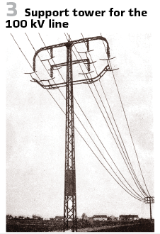
Direct neutral grounding has the disadvantage that, in the case of single-phase faults, tripping by the short-circuit protection is required. G. Faccioli published „Line Oscillations” at the proceedings of A. I. E. E. in 1911. After disconnecting the defective phase, it would also be possible with a grounded system to maintain reduced operation using the two other phases and the earth as the return conductor, since in the “Wild West” there are high-voltage distribution systems that use only one wire and the earth return conductor even for the normal power supply of small consumers. It is unlikely that this operation would be tolerated by the owners of other surrounding long-distance lines and, above all, by the telephone and telegraph administrations. An arrangement used by the

Peninsula Power Co. allows the advantages of grounding to be utilized without the disadvantage of immediate shutdown in the event of a ground fault is shown in Figure 2. As the circuit shows, the ground current disables the maximum relays and activates a bell. The principle applied here is that shutting down a power supply of several thousand kilowatts due to a ground fault should not occur without the monitor first assessing the situation, especially since many ground faults, caused by animals, branches, or vibrations of the lines, clear themselves after a short time.
If the ground fault lasts a few seconds, a switch can be opened temporarily, with the backup line taking over the load. If the ground fault is on the switched-offline, it is also switched off by the backup relays at the other end and can then be grounded and repaired. If the ring continues, this is a sign that the fault is on the line that is still switched on.
Networks with an isolated neutral point offer the significant advantage that line-to-earth faults do not lead to short-circuit currents, thus eliminating the need for shutdown. Arc faults extinguish themselves under certain conditions.
However, the disadvantages of isolated neutral point treatment include a high current at the fault location, high step voltage, and intermittent earth faults with overvoltages up to 3.5 times the line-to-earth voltages.
While cable networks, due to their symmetrical design, exhibit equal line-to-earth capacitances in all conductors, the neutral-to-earth voltage (Uo) occurring at the neutral point during normal operation is very low. Overhead line networks, however, present different conditions due to the conductor arrangement, resulting in an undesirable neutral point shift (Uo) even during fault-free operation.
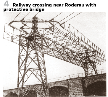
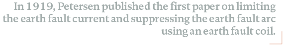
This had a particularly pronounced effect in high-voltage networks (> 50 kV), leading to the first use of twisting in 1912 for the first 100 kV three-phase transmission line in Europe, Lauchhammer-Riesa (see image). Among other things, the German Reichsbahn and the German Post Office demanded special protective devices in the form of so-called protective bridges for all crossings in public traffic areas and railway lines. (Figures 3/4).
Operational experience was relatively good. Only about 30 earth faults occurred in the first few years of operation. The cause was that common buzzards used the grounding brackets as nesting sites.
A historical overview shows that in German-speaking countries, medium-voltage networks were initially operated with a free neutral point. This operating method was convenient, and due to the small network size (low earth fault current) and the large insulation margin of the equipment, no particular difficulties arose. However, with the increase of earth fault currents significantly above 50 A, the earth fault arcs no longer extinguished themselves. Conversely, the risk of intermittent earth faults increased considerably in networks with earth fault currents below 10 A.
Therefore, between 1916 and 1918, Waldemar Petersen intensively studied the influence of earth fault current on the operational reliability of the network.
After exceeding certain thresholds, the earth fault current remained as an arc, even if the cause of the earth fault was only temporary. He recognized the connection between the residual earth fault current and a whole range of different types of disturbances, such as line breaks, insulator damage, persistent earth faults, blown fuses in network transformers, and overvoltages.
In addition, there is danger to life, for example, at pylons and substations or at the fault location. In networks with small generators, the magnitude of the earth fault current exceeds the rated current of the generator.
In 1916, W. Petersen pointed out that the minimum machine output (of lightly loaded networks) should not be determined by the network’s charging capacity. The charging capacity in the event of a ground fault was far more important, he argued, if operation was to continue during a phase with a ground fault.
One of his important findings from his investigation of intermittent ground faults was the discovery of DC charges released when the ground fault arc extinguishes. The high DC voltage that the entire network assumes relative to ground after extinguishing is the cause of reignitions and thus the overvoltages of intermittent ground faults. Technically sound surge protection is not intended to divert existing overvoltages and protect the system against overvoltage, but rather to suppress overvoltages in their formation. To tackle the problem at its root, the released charges must be rapidly eliminated. The following methods are suitable for this:
- Spark arresters with damping resistors
- Permanently installed ohmic resistors between conductor and ground
- Ohmic resistors between generator or transformer neutral points and ground
- and finally, as a last resort, the ground fault coil
Years of research into the causes of the observed overvoltages led Petersen to invent the ground fault suppression coil. When investigating the effect of ohmic resistances between the generator or transformer neutral point and earth, the calculated results of the influence of stray inductances showed that these reduced the fault current flowing through the partial capacitances of the conductors. This surprising result of the compensation effect led Petersen to his successful idea. He himself writes: “From this realization to the discovery of the earth fault coil was only a small step.
Petersen was initially impressed by the automatic protective earthing proposed by Thieme in 1916. (Figures 5/6).
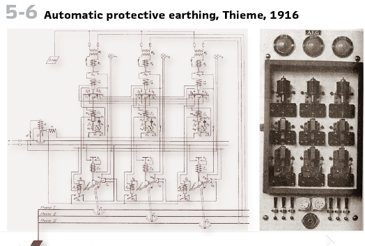
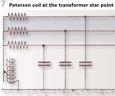
In its original AEG design, this earthing system consisted of three single-pole oil circuit breakers connected between the conductor and earth, each controlled by a zero-voltage relay, and served to relieve the earth fault location. The affected conductor was initially grounded temporarily twice. If the earth fault persisted, it was grounded a third time, but this time permanently. In 1917, Petersen first reported on the partial capacitances of overhead lines and the calculation of the earth fault current. In 1918, he published a paper on suppressing intermittent earth faults using zero-resistance resistors and spark arresters. Around the same time, he published an article on eliminating overhead line disturbances by suppressing the earth fault current and arc. Only then did Petersen develop an inductive earth fault coil at the neutral point of transformers (Figure 7).
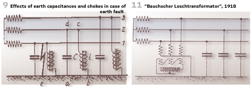
His idea was recognized by the Imperial Patent Office in 1917 under the title “Device for Suppressing the Earth Fault Current of High-Voltage Networks,” patent specification no. 304823. The main claim reads: “Device for suppressing the earth fault current of high-voltage networks, characterized in that, using the known neutral grounding via choke coils, these are dimensioned such that they draw a current at the phase voltage which is equal to or approximately equal to the earth fault current of the network.” Also patented are the arrangement of individual chokes (Figure 9) to the phases and the connection to a neutral point via the formation of an artificial neutral point.
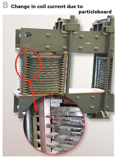
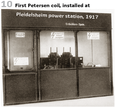
The first earth-fault coil tested in operation (cover page) was manufactured from an old AEG three-phase transformer according to Petersen’s instructions and demonstrated and put into operation by Petersen in 1917 at the Kraftwerk Altwürttemberg A.-G., Pleidelsheim hydroelectric power plant (Figure 10). It was designed for a maximum of 40 A and connected to the neutral point of one of the power plant’s four 10 kV generators. The current was adjusted by inserting chipboard between the cores and the yoke (Figure8), thus changing the air gap or the number of turns. Due to the further expansion of the 10 kV network, the coil was no longer sufficient and was donated to the Deutsches Museum in Munich in 1928.
In 1919, Petersen published the first paper on limiting the earth fault current and suppressing the earth fault arc using an earth fault coil.
In 1918, Richard Bauch proposed the Bauch quenching transformer (Figure 11), named after him. Another solution was the Pollosche quenching transformer, and in 1921, a Reittoffer arrangement, in which the quenching coil is mounted on the fourth transformer leg, was developed.
In 1919, Petersen published the first paper on limiting the earth fault current and suppressing the earth fault arc using an earth fault coil.
In 1918, W. Petersen of AEG developed a wattmetric earth-fault detection relay (see Figure 13). Its operation is similar to distance protection. The earth fault current, which increases towards the fault location, and the zero-point voltage of the network generate the greatest torque. Since the relay operates against constant damping, relays located near the fault location exhibit the shortest tripping time. Furthermore, because the relay is a reverse-current relay and therefore dependent on the current direction, all conditions for automatic and correct earth fault tripping are met.
By using the Petersen coil, AEG, through DRP 336210, supplied the watt component of the residual current, in particular due to the ohmic losses in the Petersen coil, to the earth fault relay ER via an ohmic resistor VW in 1919. (Figure 12).
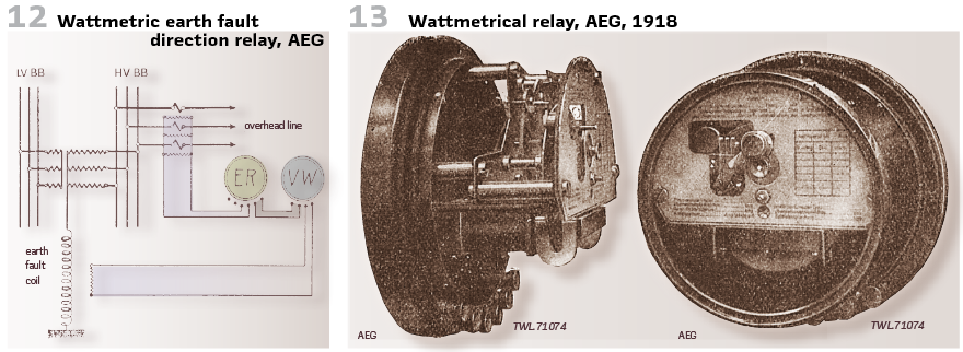
All this is possible without difficulty, since the AEG earth fault relay has very similar selecting properties in the event of an earth fault as the distance relay. This is based on the fact that in the event of an earth fault, exactly the same laws apply to the distribution of earth fault currents in the network as apply to short-circuit currents in the event of a short circuit. Furthermore, the earth fault currents also cause voltage drops in the conductors through which current flows, so that the zero-point voltage of the network is highest at the earth fault location itself, while it decreases towards the power plant. The earth fault relays near the fault location therefore receive the highest current and the highest voltage, thus developing the greatest torque, and since the relay operates against a constant damping, the relays near the fault location result in the shortest tripping time. Since the relay is also current direction dependent due to its design as a reverse current relay, all conditions for automatic correct operation of the earth fault trip are thus met.
Also, in the US such relays were used and called “watt relays”. A circuit of the watt relay used by Victor H. Todd, Westinghouse Electric Manufacturing Co., is shown in Figure 15.
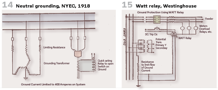
The current coil is inserted in the neutral between the transformers and the line relays, while the potential coil is energized by the drop in voltage across the resistor in the neutral of the potential transformers. This relay is set to operate at a very low value of about 1 A or less. It has an adjustable time element and can therefore be set to select between successive sections of line.
The 6600 V grid (25 Hz) of New York Edison Company was not grounded at the beginning. After a deep investigation and analysis, they decided to change this. Utilizing earth transformers connected to the system busbar a defined earth current was created and connected to an earth relay, which tripped the oil circuit breaker. The method of earthing via “zigzag” connected transformers was chosen because the generators have been delta connected- a neural connection was not available in that case. The limiting resistances have been connected to the primary side and limited the cumulated earth current for the power stations operated in parallel to 400 A. The selective earth relays, operated by the sheath current transformers could handle between 140 A and 300 A for at least 1 s (Figure 14).
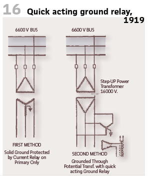
Dr. Creighton published at A.I.E.E.in 1919 the suggestion, using potential transformers with the neutral grounded and the secondaries connected in delta with a quick-acting relay in the loop (Figure 16).
Zukerman of AEG in Germany presented an Earth fault relay in 1922 (patent DRP 336210 in 1919).
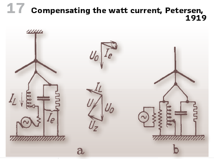
And it was Petersen of AEG who showed the first proposal to compensate the watt current with a series coil in 1919 (Figure 17.) This happened:
a) by a fixed voltage UZ in phase with IL of
b) by injecting a current into the neutral
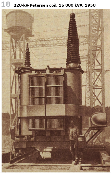
The development of the Persen coil, its application in the voltage levels up to 220 kV (Figure 18) and the further improvement of the earth fault detection will be covered in the next issues.
info@walter-schossig.de www.walter-schossig.de
thomas.schossig@omicronenergy.com
Biographies:

Walter Schossig (VDE) was born in Arnsdorf (now Czech Republic) in 1941. He studied electrical engineering in Zittau (Germany) and joined a utility in the former Eastern Germany. After the German reunion the utility was renamed as TEAG, Thueringer Energie AG in Erfurt. There he received his master’s degree and worked as a protection engineer until his retirement. He was a member of many study groups and associations. He is an active member of the working group “Medium Voltage Relaying” at the German VDE. He is the author of several papers, guidelines and the book “Netzschutztechnik
[Power System Protection]”. He works on a chronicle about the history of electricity supply, with emphasis on protection and control.
Thomas Schossig (IEEE) received his master’s degree in electrical engineering at the Technical University of Ilmenau (Germany) in 1998. He worked as a project engineer for control systems and as a team leader for protective relaying at VA TECH SAT in Germany from 1998 until 2005.
In 2006 he joined OMICRON as a product manager for substation communication products. He is author of several papers and a member of standardization WGs.