by Walter Schossig, Germany, and Thomas Schossig, OMICRON electronics GmbH, Austria
In the last issue we described the first power transmission in Germany, from Lauffen to Frankfurt in the 1891. This initiated an unbelievable development and a lot of activities in the transmission of electrical power. So we move now to the US, where an exhibition should show power in 1893. The source of this information is the Engineering and Technology History Wiki (ETHW) (https://ethw.org/Early_Electrification_of_Buffalo).
This was the era of the ‘Battle of the Currents’ with Edison as the leading proponent of direct current and with Westinghouse and others promoting alternating current. When the first execution by electricity took place in 1890 in New York State’s Auburn Prison, an ac electric chair was used. Dc proponents said the condemned murderer had been “Westinghoused.” The opportunity for a large-scale demonstration of the alternating current system to dispel fears about the system’s high voltages and display its versatility came in the spring of 1892 when bids were taken to light the grounds of the Columbian Exposition to be held in Chicago in 1893. The Exhibition used more electricity than the whole City of Chicago.
The central-station plant that supplied the fair consisted of twelve two-phase generators rated 750 kW, 60 Hz, 2000 to 2300 volts, belt driven or direct driven by five reciprocating steam engines.
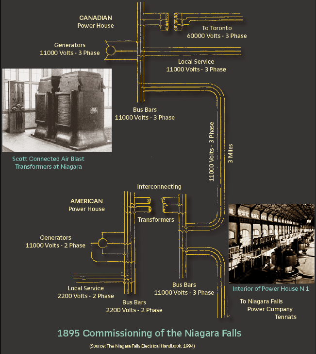
The Westinghouse exhibit in Machinery Hall was the largest plant of the Tesla polyphase system operating at that time. In addition to the lighting plant, there was an exhibit of a complete polyphase system which showed power could be transmitted great distances and then be utilized for various purposes. Taking power from the 60-Hz fair circuits was a 500-hp motor that drove a two-phase 500-hp, 30-Hz, 400-volt generator (Figure 1). This powered a 400 volt-to-10,000-volt step-up transformer, a short ‘transmission’ line, and a step-down transformer which ran induction motors, a synchronous motor plus a rotary converter for changing alternating current to direct current. The converter had a rotating armature with four slip rings for the two-phase ac and a commutator for the DC. (Figure 2).
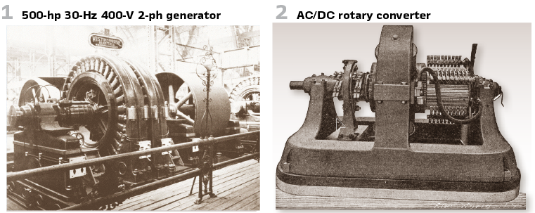
The Westinghouse polyphase exhibit was a big attraction when the Columbian Exhibition opened in the spring of 1893. Wooden models of the hydraulic turbines and governors under construction for Niagara Falls were also exhibited.
On January 14, 1896, after much difficulty, the City of Buffalo granted an electricity distribution franchise to the Niagara Falls Power Company; municipal ownership had been rejected. In June the franchise was assigned to the newly incorporated Cataract Power and Conduit Company, which was jointly organized by Niagara Falls Power and Buffalo General Electric for the purpose of the sale and distribution of electricity in Buffalo at wholesale Proposals for equipment to transmit 10,000 electrical horsepower from Niagara Falls to Buffalo were received from Westinghouse and General Electric.
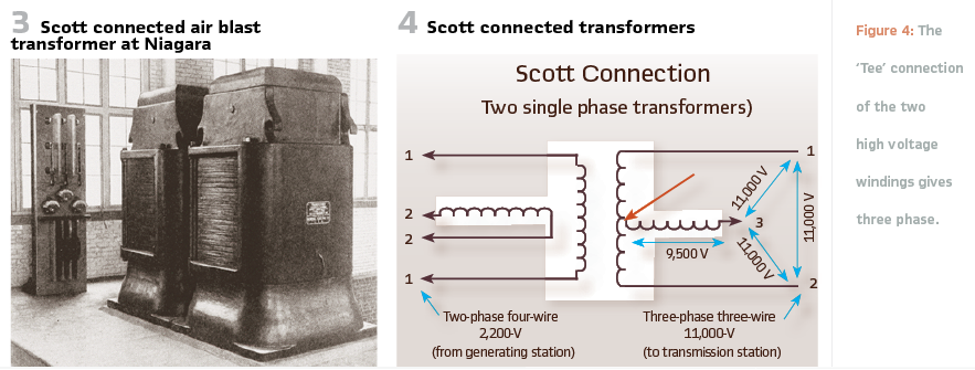
General Electric was awarded the contract for the design and construction of the transformer station in Niagara Falls, the transmission line to Buffalo and the transformer station in Buffalo, including the rotary converters to provide direct current for trolley service. Two single-phase air-cooled or ‘air blast’ 930-kW transformers were installed at Niagara (see Figure 3).
There was obviously still a mistrust of the practicality of 3 phase power throughout the electric power industry at that time. For example, according to an article from 1896 titled “Present Status of the Transmission and Distribution of Electrical Energy” in the AIEE Transactions:
Where a two-phase transmission with separate circuits is used, then if the separate circuits are wound on different armatures, each can be regulated to give a constant voltage at the receiving end. This is the case, for instance, in the large dynamos built by the Westinghouse Company for use at the World’s Fair in Chicago. The difficulty due to the uneven loading of the circuits is specially marked in the case of the three-phase system, and it is one of the principal objections that have been urged against the employment of this system for purposes of distribution.
It had already been realized, however, that the 3-phase configuration was superior for transmission from the point of view of efficiency.
Thus, special phase-changing transformers were designed by Charles F. Scott of Westinghouse in order to step up the 2-phase generated voltage at Niagara Falls to 11,000-V, three-phase for transmission to Buffalo, New York. The General Electric Company was awarded the contract to build the phase-changing transformers and so was licensed by Westinghouse to utilize the connection developed by Scott for this purpose.
Charles F. Scott: “The evolution of electric power from the discovery of Faraday to the initial great installation of the Tesla polyphase system in 1896 is undoubtedly the most tremendous event in all engineering history.” A Scott-T transformer (also called a Scott connection) is a type of circuit used to derive two-phase electric power (2- , 90-degree phase rotation) from a three-phase (3-,120-degree phase rotation) source, or vice versa. The Scott connection evenly distributes a balanced load between the phases of the source. The Scott three-phase transformer was invented to bypass Thomas Edison’s more expensive rotary converter and thereby permit two-phase generator plants to drive Nikola Tesla’s three-phase motors.
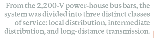
They were Scott connected from 2-phase 4-wire 2200-V to 3-phase 3-wire 11,000-V. The ‘Tee’ connection of the two high voltage windings gives three phase (Figure 4).
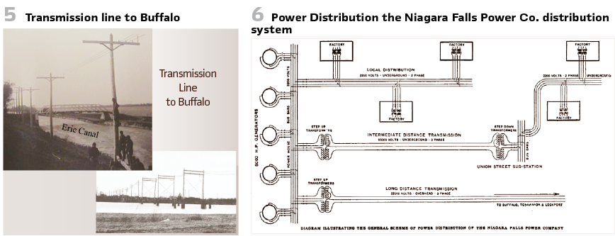
The 22-mile transmission line consisted of cedar wood poles with 12-foot pine crossarms supporting three 350,000-cmil, 19 strand, bare copper conductors (see Figure 5). The arrangement on the crossarms was originally 18 inch horizontal spacing but was changed to 36 inch triangular spacing to deter vandals who threw short pieces of wire across two or more conductors causing short circuits. Insulators proved to be a big problem. The first ones were dry process porcelain, which passed a 40,000 V dry test but were porous. About 40,000 of these insulators were rejected because they failed a 20,000 V wet test. These were soon replaced with wet process porcelain insulators, which passed a 40,000 V wet test.
At the Buffalo end, the last 4000 feet was underground cable to the generating station of the Buffalo Railway Company on Niagara Street at Prospect Avenue where three 250-kW 11,000-V to 375-V transformers connected in delta supplied two rotary converters for street railway purposes. The rotary converters operated in parallel with the trolley company’s steam engine driven 550-volt dc generators. Service was inaugurated November 15, 1896. Overall efficiency was 79.6%. In 1896, protecting devices for transmission lines were exposed by their complete absence.
The oil switch had not yet been conceived and there was no method known which could interrupt a short circuit on a line with the capacity at Niagara without shutting down the entire system. At Niagara lead fuses were used on the 2200-V side of the transformers and aluminum fuses on the 11,000-V side. At Buffalo 11,000-V aluminum fuses were used on the line side of the transformers and air circuit breakers on the load side of the rotary converters.
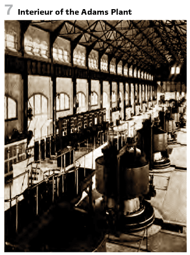
The fuses proved to be totally inadequate and were removed. The only alternative was to shut down the entire system by causing the generator field circuit breakers to trip with a persistent short circuit. Air brake switches were used for synchronizing and disconnecting but were useless to interrupt short circuits. Figure 6 shows the diagram.
From the 2,200-V power-house bus bars, the system was divided into three distinct classes of service: local distribution, intermediate distribution, and long-distance transmission. The local distribution was fed directly from the 2,200-V, two-phase, 25-Hz station bus. There was no known method by which a short circuit on a transmission line of the capacity of that at Niagara Falls could be opened without causing damage to the circuit breaker. Fuses were tried in the Adams Plant, but the interrupting duty was too severe.
They were removed because they exploded when clearing a fault and caused more trouble than they prevented. The solution was to disconnect the alternator’s field, shutting down the entire section of bus. This would not prove to be a long-term solution, however. (see Figure 7).
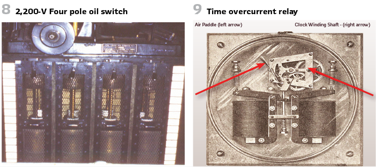
The use of recently developed oil switches, such as the 2200-V four-pole oil switch at Niagara (Figure 8) was a big step forward. Time overcurrent relays like the one shown in Figure 9 and reverse current relays enabled short-circuited elements to be removed from service without shutting down the whole system. Note the clockwork mechanism; a key was used to wind the spring and the amount of time delay was set by varying the pitch of the two-blade air paddle.
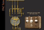
The Scott connection enabled also the connection to another country – in this case to Toronto in Canada (see title picture).
The 1893 World’s Fair in Chicago presented a series of ground detectors. The general purpose of earth fault detection in America is also to measure the voltage between the pole and the earth. While in Germany people have recently used convenient and reliable voltmeters to determine insulation, in America people are still mostly content with the previously common lamps as ground fault indicators.
Of course, information can only be obtained with lamps if there is an almost direct ground fault, or at least only if the insulation resistance is less than approx. 1000 Ω. — The earth fault control devices commonly used in central station practice can now be divided into two classes; One includes the devices for occasionally detecting an insulation defect that has occurred, the other contains the automatic ground fault indicators.
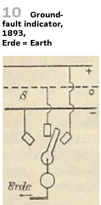
The simplest earth fault tester, as found on the latest circuit boards, consists of a signal lamp (Figure 10). For systems with 100 or 200 V operating voltage, a single one is sufficient, which, connected in series, is connected to the positive or negative pole of the network using a changeover switch, while the other pole is connected to earth.
Depending on whether the lamps shine brighter or darker, the ground fault is stronger or weaker; the defective pole is the opposite pole of the one on which the lamp burns. In this way, insulation resistances of a few hundred ohms can be estimated depending on the degree of brightness of the lamp. For three-wire systems, the changeover switch is set up in three parts.
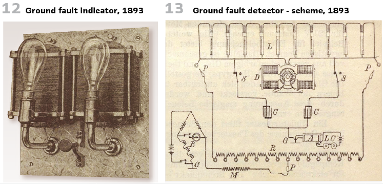
The capacitors C are connected to the main line and in the event of an insulation or earth fault, the relay A connected to earth G is activated and sets the connected alarm bells LC in motion. After opening the switch S and plugging the resistor R, the fault resistance can be measured using a Wheatstone bridge (Figure 13).
In a ground fault detector for alternating current two primary coils of two small transformers are connected in series between the poles of the primary (high voltage) line, while the middle of this connection is connected to earth. A signal lamp is connected to each of the secondary windings.
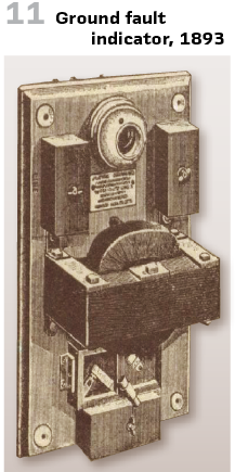
If a ground fault occurs, a potential shift in the secondary circuit is caused as a result of the shunt to one of the primary coils, so that the ground fault can be deduced from the different brightness of the lamps. (see Figure 11, Figure 12).
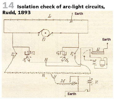
Figure 14 shows the ground detector designed by Rudd and often used in Chicago to check the insulation of arc light series circuits. The capacitor method initially only uses the automatic signaling of earth faults that have occurred, while the size and location of the fault is determined more precisely by galvanometric means with the help of the bridge combination.
In 1890, interconnected operation with a three-wire direct current network began in Berlin. We slowly learned that the grounded center conductor must not be protected.
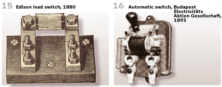
By grounding the center conductor in the DC or AC network, it was achieved that the insulation only had to be designed for half the voltage and a ground fault in an external conductor leads to a short circuit and thus to the activation of a fuse or so-called “automatic off switch”. Edison used lead strips as a fuse in 1880, “Edison lead switches” (Figure 15).
“Knife switches” with overcurrent magnets were used in the US. In the switched-on position, the bracket with the blade contact is held by a latch.
The switch-off was affected by the overcurrent magnet, which releases the latch and pressed the bracket with the blade contact into the off position. Figure 16 shows an example from Europe.
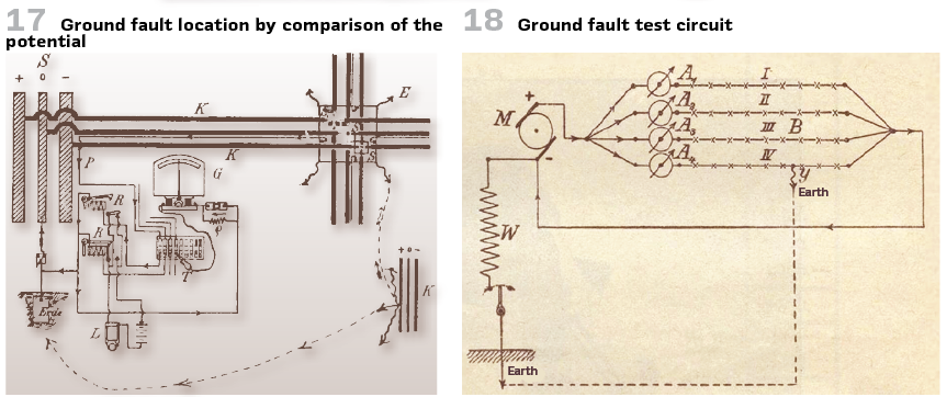
The Berlin municipality provided the cables for the three-wire system with insulated test wires, which were used to monitor the voltage in the supply and distribution boxes in the headquarters. In 1893, C. Agthe and M. Kallmann used the cable test wires to report errors by comparing the error-related increase in the earth potential at the fault location with the potential of a “normal earth” located in the control center (Figure 17).
In addition to these ground detectors, in the case of several arc lighting circuits connected in parallel, a resistor W measuring a few amps can be connected between the negative pole and earth and the faulty line can be determined by observing the deflections of the ammeter. (Figure 18).
One could see it as a harbinger of the low-resistance star point earthing (German word KNOSPE) to be discussed in a later edition.
info@walter-schossig.de
www.walter-schossig.de
thomas.schossig@omicronenergy.com
Biographies:
Walter Schossig (VDE) was born in Arnsdorf (now Czech Republic) in 1941. He studied electrical engineering in Zittau (Germany) and joined a utility in the former Eastern Germany. After the German reunion the utility was renamed as TEAG, Thueringer Energie AG in Erfurt. There he received his master’s degree and worked as a protection engineer until his retirement. He was a member of many study groups and associations. He is an active member of the working group “Medium Voltage Relaying” at the German VDE. He is the author of several papers, guidelines and the book “Netzschutztechnik
[Power System Protection]”. He works on a chronicle about the history of electricity supply, with emphasis on protection and control.
Thomas Schossig (IEEE) received his master’s degree in electrical engineering at the Technical University of Ilmenau (Germany) in 1998. He worked as a project engineer for control systems and as a team leader for protective relaying at VA TECH SAT in Germany from 1998 until 2005.
In 2006 he joined OMICRON as a product manager for substation communication products. He is author of several papers and a member of standardization WGs.