by Marcel Geor, Alex Lippitt, and Hayden Alves Tekron International Ltd., New Zealand
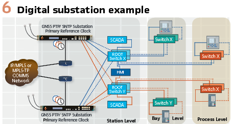
Process bus is the digital transmission of process measurements between the substation switchyard and digital protective relays in the protection and control room. In full digital substation applications with process bus implementing IEC 61850, accurate, and error free time synchronization is highly important for synchronization of current and voltage measurements between interdependent Protection and Control Systems.
IEC 61850 is a standard that defines a common communication model to facilitate interoperability between vendors. A component of this standard, IEC 61850-9-3, covers the timing protocol used. IEC 61850-9-3 builds on the IEC 61588:2009 – Standard precision clock synchronization protocol for networked measurement and control systems; more commonly referred to as Precision Time Protocol (PTP). PTP (Figure 1) introduces a method of providing time synchronization across a digital network.
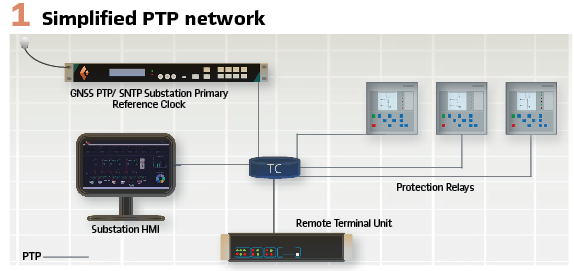
This protocol leverages off dedicated PTP hardware which time stamps packets as they arrive and leave the network port. This facilitates a more accurate calculation of propagation delay through the network.
Through an exchange of several time stamped messages a slave device can calculate the Time of Day (TOD) to an accuracy in the nanosecond level.
The message types are:
- Sync messages which contain the time value from the master clock in the form of the number of seconds and nanoseconds since midnight on 1 January 1970
- Peer delay messages are exchanged between adjacent IEDs to calculate the propagation delay over the link
- Announce messages carry information from the grandmaster including time traceability, time accuracy, and several other configuration and network variables.
PTP provides two methods of transferring accurate sync and peer delay time stamped packets between two devices the first of which is one-step operation.
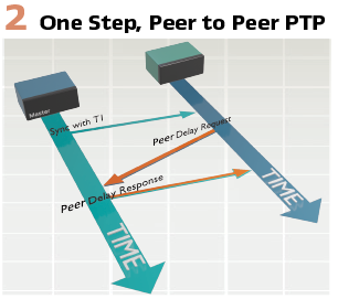
In one-step operation the transparent clocks update the time error in the messages as it passes through the network. This method requires heavy hardware processing to modify the packets, however minimizes the number of packets sent across the link. (Figure 2).
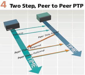
The alternative method is a two-step operation. Two-step operation uses follow-up messages to reduce the hardware processing power required. The first message will contain an approximation of the time error, and the follow-up message will contain the exact time error. This increases the complexity of the software implementation and increases the packet traffic on the network. (Figure 4).
Within an IEC 61850-9-3 PTP design, there are several clock types that could exist within the network.
- Ordinary Clock (OC) has a single PTP port (or pair in the case of PRP) within a domain and can be a master or slave. An Ordinary Clock can be a grandmaster Clock (GM)
- Boundary Clock (BC) has multiple ports (or pairs of ports in the case of PRP) and is usually a slave in a domain, and a master in one or more other domains. A Boundary Clock can be a Grandmaster Clock
- Transparent Clock (TC) measures the delay of a PTP packet from ingress to egress and adds it to the correction field as the PTP Packet passes through. It is stateless and is neither a master nor a slave
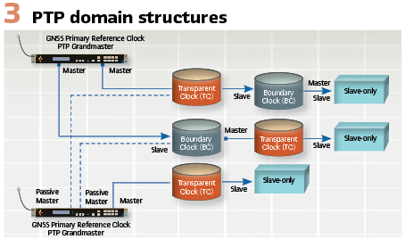
A PTP domain is structured in a master-slave hierarchy with the master of the domain being called a grandmaster clock. This will usually be referenced to one or more GNSS constellations or some other form of UTC time traceable source. The grandmaster is selected by the implementation of the Best Master Clock Algorithm (BMCA) between two (or more) master clocks. (see Figure 3).
A major component of PTP is the Best Master Clock Algorithm (BMCA). A clock redundancy method built into PTP which ensures the best reported clock is used as the source of time on the network. When a PTP clock is connected to a network, it will listen to see if a grandmaster clock is already present. This provides two possibilities; if a grandmaster clock does not announce its presence, then the clock will advertise its clock quality through the announce message.
If no clocks respond, then it will assume the role of the network grandmaster. The second possibility is when another master clock is present, in which case the clock will compare its accuracy versus the reported accuracy of the grandmaster clock sent in the announce message.
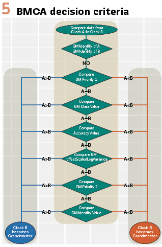
The new clock on the network will go through a series of checks (Figure 5) to determine if it should become the new network grandmaster. If the new clock determines it would be better suited as the grandmaster, then it will become the network grandmaster clock. Otherwise it will listen as a passive master until the grandmaster’s quality degrades.
With IEC 61588:2009 however, the low-level implementation is left open. For simplicity PTP profiles have been developed which further standardize the implementation of PTP by defining the operating parameters for specific industry applications. IEC 61850-9-3 commonly referred to as the Utility profile has been developed for Power Utility applications.
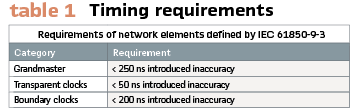
As well as defining specific operating parameters included in the PTP profile, it also defines timing requirements for the grandmaster, transparent, and boundary clocks.
A network consisting of these elements can achieve accuracy of better than 1 µs after crossing approximately 15 transparent clocks or 3 boundary clocks (Note: As described in IEC 61850-9-3 time inaccuracy is defined as the time error not exceeded by 99,7 % of the measurements evaluated over a series of 1,000 measurements when the clock is in a steady state.) (Table 1).
Lastly, IEC 61850-9-3 defines the clockClass fields used to indicate the traceability of the time provided by the grandmaster clock. IEC 61850-9-3 defines the clockClass asshown in Table 2.
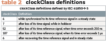
In the table the second entry for clockClass 6 is to indicate the re-entry of synchronization, when the clock has recovered synchronization to its primary reference source and its time inaccuracy is less than 250 ns.
Process Bus Requirements
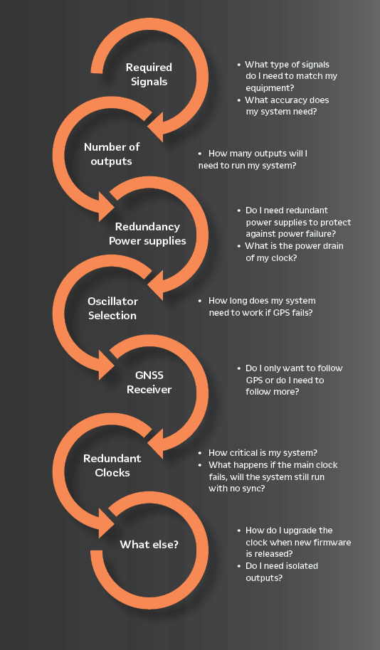
When designing a time synchronization architecture, it is important to understand the devices’ requirement of time synchronization, and how they will behave when this source is lost.
IEC 61850-5:2013 defines the timing classes required for an Intelligent Electronic Device (IED) to carry out its function. These timing classes cover a wide range of applications and therefore give a wide range of accuracies. T5, the highest level of accuracy, is recommended for applications implementing process bus.
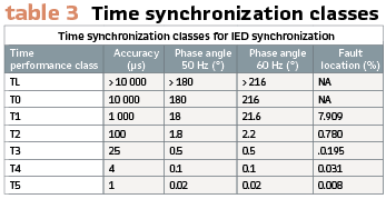
It is important to note, whilst an application may require a certain time performance class, a vendor’s IED may have been designed to a higher performance class. Vendors can develop a common hardware platform which is used across multiple applications some of which require the higher-level performance classes. (Table 3).
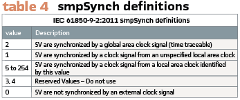
IEC 61850-9-2:2011 defines a field called smpSynch, which indicates the sync source of the IED publishing sampled value packets to the network. This value is used by the sampled value (SV) subscriber IEDs to ensure values of the SV packets are synced to a common time base to required accuracy levels. (Table 4).
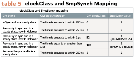
IEC 61869-9:2016 provides a digital standard for instrument transformers according to IEC 61850. This standard provides the mapping of IEC 61850-9-3 clockClass variable to IEC 61850-9-2 smpSynch variable. (Table 5).
What Happens when Sync is Lost?
A good design topology will ensure the accuracy requirements of the IEDs are met. This accuracy, however, can only be ensured whilst the clock maintains synchronization to its time reference, which in most cases is GNSS (Global Navigation Satellite System). It is when GNSS synchronization is lost, that the behavior of the substation must be evaluated.
In the event the network Grandmaster loses its primary reference source. It will move into holdover state and broadcast its clockClass as 7. It is during holdover that the clock relies on its internal oscillator to provide an accurate time. Oscillators, however, are not stable and drift over time, degrading the clocks accuracy. When the clock accuracy has degraded to a point where it can no longer provide accuracy to within 250ns the clockClass will move to 52, then 187 when the accuracy exceeds 1 µs. It is during these two states that IEC 61850-5 time performance class, T5, cannot be maintained.
At this point merging units will start advertising a smpSynch value of 1 (local clock) or the Grandmaster ID (5 to 254), and any IEDs requiring time performance class T5 such as PMUs, travelling wave fault location, and line differential schemes will revert to a blocking state or stop performing their core function.
This will continue until such time as the clock recovers and advertises clockClass 6. Other protection functions within the substation, will typically remain unaffected as long as the SV Subscriber IEDs are comparing packets from publishers synced to a common time base to required accuracy levels.
Antenna Failure: GNSS antennas are a single point of failure. Installed at the highest point of the building, they are exposed to lightning strikes, which can cause damage to the antenna system and connected devices. Surge arrestors should be installed to minimize any damage caused, however in most cases the antenna will no longer function and will need to be replaced.
A strategy to help mitigate against the risk of antenna system failure is to utilize a redundant antenna system installed a reasonable distance apart. Currently this is done by utilizing two-antenna systems through two isolated GNSS receivers. This ensures that in the event of an antenna outage, one receiver will remain active providing a time signal to the clock.
When a full outage occurs, and the device is no longer able to receive any GNSS signal, the clock will enter its holdover state and revert to a local time source provided by an internal oscillator. There are several different types of oscillators – the entry level oscillator is a VCTCXO (Voltage Controlled Temperature compensated crystal oscillator), which can maintain an accuracy of 250ns for a matter of seconds. A VCOCXO (Voltage Controlled Oven Controlled Crystal Oscillator) can extend the period to 1 or 2 hours, and a Rubidium oscillator can extend that even further to several hours. It should be noted that each oscillator will differ from unit to unit due to the unique nature of the tuning and manufacturing of each oscillator and as such the accuracy threshold of each oscillator may vary.
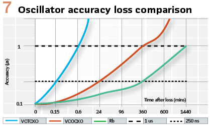
The graph in Figure 7 can be used as a guide to determine how long the different oscillator types may stay in holdover before significant loss of accuracy.
Poor Satellite Reception: Antenna placement requires thought and consideration when installing a clock system. Ideally the antenna is placed at the top of the building with an unobstructed view of the sky above and around it.
However, this is not practical in all installations. In the case where the view is obstructed and sync is only able to be achieved periodically, utilizing one of the high-quality internal oscillators described above will allow the clock to ride through short periods of lost GNSS reception.
GNSS Jamming and GNSS Spoofing: GNSS signals are extremely weak at the Earth’s surface, which means that they can be easily drowned out by other signals in the same frequency band. GNSS jamming is the act of overpowering the GNSS signal with another signal and a common threat to GNSS receivers is radio interference. This can be unintentional, such as noise, or an intentional attack. Unintentional noise is usually caused by other electronic devices, such as radio transmitters, radio amplifiers and switching power supply units.
GNSS spoofing is a more sophisticated threat to GNSS receivers, where an adversary deliberately generates false satellite signals in an attempt to mislead the receiver and cause disruption. Advances in technology are allowing potential GNSS spoofing devices to become more compact, less costly, and more readily available, which means that GNSS spoofing is becoming less of a theoretical threat and more of an actual threat.
Protection against GNSS Jamming and GNSS Spoofing can be performed in several ways:
Multiple GNSS constellations and frequency bands: There are now several navigation systems in orbit around the Erth. The four most advanced are: GPS, GLONASS, Beidou and Galileo. Each can be used separately or combined to provided time synchronization. Utilizing more constellations, increases the number of satellites used for time synchronization and can highlight any irregularities in a single constellation. Building on to this, each constellation is transmitted over multiple frequency bands adding further precision, protection and reliability to the timing system. Another benefit of using multiple constellations is it also reduces the likelihood of lost GNSS reception.
Analysis of GNSS Satellite data: With a clock installed in a stationary position, a log of satellites, orbital information and signal levels can be recorded. Using the historic information, irregularities in the behavior of individual satellites can be detected and preventative action can be taken. Significant changes in information compared to preceding data may indicate GNSS spoofing.
Characterization of available sync sources and GNSS sampling: Utilizing highly stable Rubidium or OCXO reference modules, a primary reference clock can monitor and characterize available sync sources and filter any erroneous or unstable sources from the timing solution. Utilizing multiple GNSS receivers and external sync sources increases the ability for a primary reference clock to detect logical errors, reference pulse and frequency shifts.
Multiple GNSS Antennas: Radiation noise and jamming usually originate from a single source. Utilizing two or more antennas with some physical distance between them, would make it more likely that one is further from the source than the other, and therefore less affected. With both antennas connected to the same system, the system can then select the antenna which is less affected.
Similarly to GNSS jamming, spoofing requires subjecting the receiving antenna to sufficiently strong signals, in order to overpower the real GNSS satellite signals. Therefore, two antennas would make a successful spoofing attack more difficult in the same way that a successful jamming attack is made more difficult.
Two antennas also make successful spoofing attacks more difficult in other ways. If an adversary simply increases the power of their spoofing signal in order to make the signal sufficiently strong at both antennas, this allows the spoofing attack to be easily detected. This is because such an attack can only simulate one antenna position, which would cause the signals received by both antennas to indicate that they are at the same position.
Alternatively, if an adversary attempts to generate spoofing signals from two separate sources simultaneously, they will need to achieve precise synchronisation between those sources, otherwise the attack can be easily detected by the time difference between the signals received by the antennas. For a GNSS clock/time server, the response to detecting spoofing that is preventing the use of real GNSS satellite signals can be to raise an alarm to inform network operators and go into holdover, a state in which it can continue to provide timing signals derived from an internal oscillator until network operators plan a course of action.
Alternate Synchronization Sources: The final method of protection against GNSS based attacks is to utilize other time references outside of GNSS. In some cases, a telecommunication backhaul implementing ITU-T G.8275.1, Precision time protocol telecom profile, may be utilized. It is currently not possible to implement a boundary clock at the substation, synchronized through the telecommunication backhaul, and meet IEC 61850-5 time performance class T5. It can be used to enable sanity checking of the Time of Day.
However, PTP High Accuracy profile (currently known as White Rabbit) has been incorporated in the latest IEEE1588-2019 standard and will provide accuracy an order of magnitude better than what is currently achieved with ITU-T G.8275.1. This improvement will allow a Substation Primary Reference Clock to synchronize to the Telecom backhaul following loss of all GNSS sources and continue to provide time synchronization meeting IEC 61850-5 time performance class T5.
Power Supply Failure: The resiliency of a system relies on reducing single points of failure. Power supplies and network infrastructure are two of the most common points.
Power supplies, both internal to the clock, and external supplying the clock are common causes of failure. Power supplies can be subjected to voltage transients and surges, which if not handled correctly can damage the supply.
IEC 61850-3 and IEEE 1613 have identified this and require the highest pass level for both transient and surge safety standards. In order to help mitigate some of the issues of a power supply failure it is recommended that dual power supplies are chosen. This means that if one power supply is to fail there is a redundant back up that is capable of seamlessly taking over.
Network Mitigation: A network relies on switches, transparent clocks and cabling to operate. Installing two grandmaster capable clocks at different points can reduce the reliance on a single switch and connection. PTP’s BMCA will handle the grandmaster rollover, if the grandmaster clock loses connection with the network.
A second method of network redundancy is to implement the IEC 62439-3 Clause 4:2016; Parallel Redundancy Protocol, (PRP). PRP essentially duplicates your network to form two sub-networks, then each message is sent across both networks. A clock supporting PRP will use two Ethernet ports to provide the same time message across both networks.
At the receiving end, the IED will check that both messages arrive, discard one and use the other for time synchronization. If one message is lost, the IED will raise an alarm to indicate this, but can still maintain its accuracy seamlessly through the messages received from the other network.
Conclusion: Understanding how each function of the substation is affected when time synchronization is lost, and how protocols and different standards’ influence the behavior, is important to understanding how preventative measures can be implemented. The solution for critical infrastructure utilizes the elements below to mitigate and prevent loss of timing:
- Implementing two or more primary reference clocks with dual power supplies, reduces the risk of failure of any one device compromising the entire system
- Each clock is utilizing two antennas to mitigate against lightning strike, and to enable GNSS jamming and spoofing detection
- Each clock has two multi-band and multi-constellation GNSS receivers enhancing GNSS jamming and spoofing detection, allowing further characterization of sync sources, and sanity checking
- Each clock contains high stability OCXO or rubidium reference modules to ride through periods of GNSS unavailability, and to characterize sync sources
- Telecommunications backhaul is used as a redundant sync source and facilitates sanity checking Time of Day
- PRP is implemented to facilitate hardware and link redundancy seamlessly
Biographies:
Marcel Geor is the Regional Manager for Asia and South America at Tekron International Ltd. He has been working with Utilities, Systems Integrators, and Consultants to implement robust time synchronization designs within Protection and Automation Systems. In addition, he provides a conduit to ensure feedback from end users design and operational personnel reaches the team at Tekron.
Alex Lippitt is the Lead Technical Engineer at Tekron International Limited. He received a Master of Engineering (MEng) from the University of Canterbury, New Zealand. His broad product and industry application knowledge have enabled him to migrate into the role of Lead Technical Engineer, where, as a major stakeholder in product development, he provides technical and functional direction into the future development and roadmap of Tekron products.
Hayden Alves joined the Tekron crew as a graduate in 2018. Moving from strength to strength, Hayden has worked with industry leaders across the globe to create impactful content for the international community looking to implement world-class timing solutions into their networks.