by Chee-Pinp Teoh and Graeme Lloyd, GE Grid Solutions, UK, Rich Hunt, GE Grid Solutions, USA, and Gerardo Rebollar, GE Grid Solutions, France
The growing adoption of process bus and the desire for a digital substation is leading to a new interest in the concept of centralized protection and control, where all protection functions for a substation are combined into a single device. When considering implementations of this solution, it is important to remember that this device will be installed in a substation and must meet all the expected environmental and performance requirements for protective devices in substations.
Importantly, a centralized protection device must be a technologically mature solution, robust and self-supervised platform, using proven protection algorithms, scalable for any substation size, on hardware capable of the expected 20-year service life.
This article describes one specific actual implementation of such a system for distribution substations, based on an existing transmission class protection relay. This centralized distribution system takes advantages of features already developed for the transmission protection platform, including:
- Proven protection algorithms for feeder, bus, and transformer protection
- A robust cyber security implementation
- Support for multiple SCADA protocols
- Support for IEC 61850, including sampled values subscription
- Numerous communications ports to support separate connections to station bus, process bus, and engineering networks simultaneously
A growing requirement for distribution substations is the ability to integrate into wide area monitoring, protection and control schemes. As the device is based on a transmission-based relay platform, this ability is quickly met by including multiple Phasor Measurement Units, and the use of Routable GOOSE to provide inter-station events and control indications.
Centralized Protection and Control System (CPC)
Centralized Protection and Control is a concept to combine the function of several IEDs into one single hardware. This allows more efficient use of the processing power and achieves cost saving by reducing the number of hardware used. While achieving the cost saving is important, CPC shall not compromise the stability and neglect the reliability offered by the conventional solution. Therefore, it is important to find a balance of saving without overlooking the criticality of power system operation.
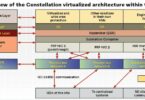
Centralized Protection and Control is not just about a single centralized protection device, because this device alone will not bring benefit to the user. CPC is a system involving process level digitization and a substation HMI, along with interfaces to wide area monitoring and control as in the Figure on page 38 (on the left). Having all functions running in one centralized hardware opens up some new requirement too, such as the need of robust cyber security in a CPC unit, redundant system to prevent maloperation due to a faulty device, and time synchronization.
Process Level Digitization
The process level is the input and output interface for the primary equipment. Digitization takes place in rugged I/O devices to convert the analogue measurements and statuses into digital messages using the data models and message formats of the IEC 61850 Standard. IEC 61850-9-2LE defines two distinct sampling rates for the SV-based process bus:
- 80 samples per nominal system frequency cycle
- 256 samples per nominal system frequency cycle
80 samples per cycle is sufficient to satisfy most of the common protection functions, whereas 256 samples per cycle is used for high-speed functions such as power quality monitoring and digital fault recorder.
Process bus should facilitate flexibility and adaptability by providing all basic data for state, status, and control of the substation to the station level for protection, automation and control application integration. This digitization and process bus turn field wiring of primary equipment into a one-time exercise to interface to input/output devices and eliminates the need for a wiring interface to control devices, protective relays, and especially the centralized protection device.
Merging Unit (MU): To digitize process bus, Merging Unit is used to convert the analogue measurement to IEC 61850-9-2 Digital sampled values (SV). IEC 61850-9-2 SV represents primary current and voltage measurements as instantaneous digital samples.
Remote Input Output unit (RIO): As for status and control function, the Remote Input Output unit is equipped with a high number of contact inputs and outputs to monitor the status and control of circuit breakers and switches and to respond to control and tripping indications from other devices. A RIO can be equipped with High Speed High Break (HSHB) contact outputs for protection tripping purpose, to compensate for the delay of publishing and subscribing by GOOSE traffic.
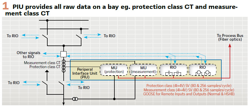
Process interface unit (PIU): Process interface unit is a term this article refers as to a multi-functional merging unit. A PIU is a single device that combines both MU and RIO functions, extending to cover all functions required at the bay level. The limits to PIU functionality are defined by suppliers. A well-defined PIU will have multiple sets of CT and VT inputs to connect to both protection class current transformers (CT), and measurement class CTs. A PIU should also support multiple SV streams with different data rates. A PIU can also have HSHB contacts for tripping and control purposes
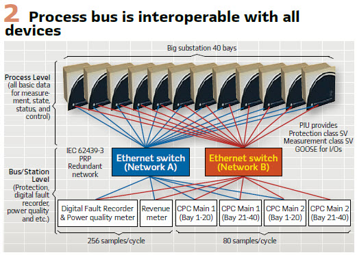
A well-defined PIU should support all the required inputs and outputs for a single bay in a single unit, as in Figure 1. The proposed goal of the PIU is illustrated in Figure 2: the SV and GOOSE messages from the PIU interface to any device in the substation, supplying the appropriate data at the appropriate data rates for the applications. CPCs are the centralized protection and control scheme. The revenue meter normally is an independent approved meter device used by the utility for the consumer revenue purpose. The Digital Fault Recorder and Power Quality Meter can work on the same process bus network for monitoring purposes.
Centralized Protection Solution Today
There are many permutations of how centralized protection and control can be implemented. Proof of concept CPC devices have been based on industrial computers, due to the needs of software development, and not the true requirements of substation protection device.
Industrial computers are commonly used in utility substations to run more software-based applications such as SCADA services, control functions, HMIs, DER management, wide area fault detection and isolation, and microgrid integration and control. However, protection functions require a real time consistent and deterministic 10 ms-40 ms operating time.
The challenge to implementing protection functions in an industrial computer is to have a real-time operating system to run protection applications. The concern is in part due to technical considerations about running real-time and non-real-time operating systems in the same device for 24 hours a day, 365 days a year for a 20-year service life.
Also, the CPC system needs to protect a high number of bays, for example 24 bays for a typical size substation. This will require the computer to process large numbers of SV, including filtering, re-sampling, and handling missing samples deterministically. The conventional relay relies on Field Programmable Gate Arrays (FPGA) to manage values data, but FPGAs are not typically available in a standard industrial computer.
It is also important to remember that centralized protection devices will be installed in substations and must meet all the expected requirements in substations.
The device must pass all the environmental tests specified in IEEE 1613 and IEC 61850-3, including electromagnetic interference, surge immunity, and fast transients. For a CPC to be a successful solution, a utility must have confidence in the computing platform, both the hardware and the software or firmware.
Centralized Protection Solution with Proven Transmission Relay
A realistic approach to CPC is to base the design on well proven transmission class relay. Once relays become optimized for process bus, the only limitation to the number of protection zones is the number of SV streams, and the capabilities of the processor to handle the data and the functionality.
Busbar protection relays are coming on to the market that accept up to 24 SV data streams, so the complete protection of small substations in a single relaying platform is possible.
A good concept to further prove CPC is to start with protection of a complete distribution substation. This involves a limited number of protection functions to use, lower risk in case of performance issues, and easier integration into the power system.
The CPC device therefore uses protection algorithms already developed for the relay platform, simply implementing more instances of these proven functions.
Proven protection algorithms for feeder, bus, and transformer protection: By utilizing the spare processing power in an existing transmission-class protective relay hardware, this is relatively simple concept to develop off of existing hardware platforms. Because it is based on an existing relay platform with a proven operating history in substations, this solution offers a more secure, mature, and stable solution.
Proven hardware platform: A transmission class protection relay is a custom hardware specifically designed and type tested to the highest requirement of the harsh substation environment. The relay has comprehensive device health diagnostic tests at startup and continuously during run-time, preventing any failure to cause malfunction to the grid system. A transmission class protection relay also has a full portfolio of hardware options such as redundant power supply, conformal coating to protect the printed circuit boards, inter-substation C37.94 direct fiber communication, RTDs option, contact Inputs/Outputs option.
The hardware cost for a transmission class protection relay is comparable to an industrial computer. However, the relay platform is designed to operate in the harsh environment of a utility substation for more than 20 years, with a proven history of reliability. This far exceeds the shorter design life of an industrial computer.
A robust cyber security implementation: The relay platform is already implementing cyber security that meets utility requirements. As the platform is upgraded for new requirements and capabilities, this is automatically done for the CPC as well. The relay platform meets NERC CIP, NIST, ISO, provides remote authentication, authentication without passwords, RBAC, syslog, encryption.
Support for multiple SCADA protocols (IEC 61850 and legacy protocols): The transmission class relay supports the most popular industry standard protocols enabling easy, direct integration into monitoring and SCADA systems such as IEC 61850 Ed. 1 and Ed. 2 Station Bus, IEC 61850-9-2LE / IEC 61869 Process Bus, and IEC 61850-90-5 PMU over GOOSE. Also, legacy protocols such as DNP 3.0 (serial & TCP/IP), Ethernet Global Data (EGD), IEC 60870-5-103 and IEC 60870-5-104, Modbus RTU, Modbus TCP/IP
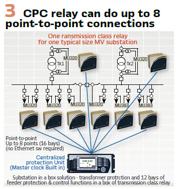
Numerous communications ports to support separate connections to station bus, process bus, and engineering networks simultaneously: A transmission class relay is designed to support different communication network architectures, including SCADA/station bus, independent engineering access port, and process bus networks. This includes enough ports for each network to support industry standard communications redundancy methods such as PRP (parallel redundancy protocol) and HSR (high-availability seamless redundancy). For small distribution substations, it is convenient to have up to 8 process bus ports to allow simple point-to-point communications, without a network or switch, as in Figure 3.
Wide area monitoring and control: Using a transmission class protection relay as a CPC automatically brings in other transmission features such as synchrophasors. The device can act as a phasor measurement unit (PMU), streaming data as per IEEE C37.118 or using R-GOOSE and R-SV as defined in IEC 91850-90-5. This means the CPC can easily integrate into wide area monitoring and protection and control schemes, as well as provide inter-substation signaling.
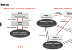
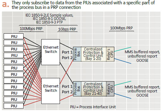
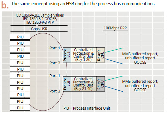
Scalable solution: The number of bays in the substation is getting higher. The CPC solution must be scalable, down to small few bays substation and up to many bays in huge substations. A CPC is only as scalable as the number of SV streams the device can subscribe to. Once this limit is reached, multiple CPC devices are required. For example, for a smaller substation with 20 bays, a single CPC unit box will do; whereas for a larger substation of 40 bays, two CPC units could provide adequate protection.
Figure 4a illustrates two CPC units connected to the process bus network, but they only subscribe to data from the PIUs associated with a specific part of the bus. Figure 4b shows the same concept using an HSR ring for the process bus communications.

Substation Human Machine Interface (HMI)
A CPC solution using an industrial computer as the hardware platform must connect to a monitor to display status and information. This provides a Human Machine Interface but the monitor typically is not built for the rugged substation environment. This could be a problem because an MV substation may have a control room.
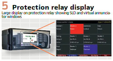
Built in graphical LCD & virtual annunciator windows: A numerical protection relay today is advanced and user friendly. Some even offer large seven inches graphical LCD display ordering option which can display the live status of single line diagram (SLD) on the protection relay itself. As the LCD is built in the relay, it has been designed to work in a substation. As in Figure 5, The same LCD can also be programmed to display as a virtual annunciator window.
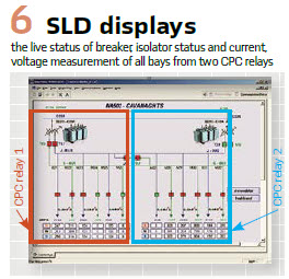
User friendly multi-functional centralized HMI toolsuite: If a substation HMI is a preferred solution over the relay LCD, the relay toolsuite software can offer a similar HMI display. The relay toolsuite offers complete feature such as Open Platform Communication (OPC) server integration for database management, remote monitoring, third party device monitoring. While the relay toolsuite requires to be hosted on a PC, but this typically can be hosted on the gateway computer. If the substation is unmanned, the HMI will only be required when the user visits the substation, to which the user can connect directly with a laptop. CPC is a scalable solution, where a big substation with many bays will require more hardware. The relay toolsuite can communicate to multiple CPC relays and act as a centralized HMI and data repository. The toolsuite displays SLD with the breaker, isolator status and current, voltage measurement of all bays in the substation collected from two CPC relays on a polling basis. (Figure 6).

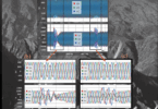
Each CPC unit has its own oscillography recorder and sequence of events record built in. In this case, the HMI toolsuite can act as the integrator, which it automatically downloads from each CPC unit and stored in a centralized, system-wide, sequence of event record as shown in Figure 7.
Fail Safe & Redundancy
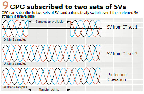
Redundant SV sources: Since PIU can have multiple analogue inputs, cross connecting two bays’ CTs and PIUs as shown in Figure 8 is possible. Having this connection can offer redundant SVs publishing.
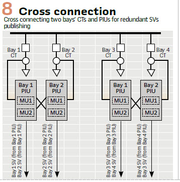
As an example, in the event of Bay 1 PIU failure, the Bay 2 PIU continue to publish the SVs for Bay 1 CT. The CPC unit can detect the loss of SV publishing on the faulty Bay 1 PIU and automatically switch to the SV subscription to Bay 1 SV from PIU2.
Seamless switching will allow protection and control function to operate correctly as shown in Figure 9. This redundant protection scheme was not possible in the conventional protection without significant additional cost and complicated wiring. However, with the multiple analogue inputs PIU, this can offer additional security and reliability at the small cost of connecting of adding another analogue input at the PIU.The one practical concern using redundant SV sources is the CPC unit has a fixed number of subscriptions to SV streams. Every redundant SV source reduces the number of bays that can be protected by one.
Thus, a fully redundant SV source can protect half the number of bays. However, thanks to the scalable relay solution as discussed above, another pair of relays could be added to cover all bays.
Time Synchronization
For proper operation of a CPC system, it is necessary that CPC and PIUs are time synchronized to each other to ensure protection functions to operate properly. The proper method for time synchronization for process bus is to use one of the industry-specific application profiles of IEEE 1588 (or PTP, “precision time protocol”) as the protocol, over the communications network. The CPC can be designed to act as an IEEE 1588 master clock to the process bus network. In normal operations, the master clock in the CPC device is synchronized to the substation master clocks. However, if the substation master clocks are no longer available, all PIUs communicating to the protection will be synchronized with the same relative time to the CPC device, allowing protection functions to remain in service. CPC does not require absolute time synchronization, but only relative synchronization between the PIUs and CPC.
As long as all the PIUs are synchronized to the same source, the CPC relay, the SV streams can be aligned and used for protection, including the low impedance differential for transformer and busbar. This therefore allows the application of the same CPC protection without the need of a satellite clock or absolute time synchronization.
Conclusion: A transmission class protection relay not only offers a good alternative to the industrial computer-based CPC solution, but it is a much more mature and proven solution having been used in transmission. For example, a transmission class protection was designed for a harsh environment, type tested for IEEE 1613 and IEC 61850-3. Using transmission class relay as a CPC offers many other benefits such as IEC 61850-90-5 PMU & R-goose functions, teleprotection, IEEE 1588 master clock built in, legacy communication protocols which is currently lacking on the industrial computer-based CPC.
A transmission class relay was designed to operate for 20 years life in the substation and offers peace of mind after installation. Process bus MUs and PIUs are future proof and should have facilitated flexibility and adaptability by providing all basic data for state, status, and control of the substation to the station level from the beginning.
Biographies:
Chee-Pinp Teoh has a B.Eng (Hons) from University Kebangsaan Malaysia and an MBA from University Putra Malaysia. He is also a Professional Engineer registered in Malaysia and a member of Institution of Engineering and Technology UK, Institute of Engineer Malaysia and UK representative for a CIGRE B5 WG. He has rich experience in Transmission and Distribution protection relay applications. Presently, Chee Pinp is the Product Manager for GE Grid Solution, based at Stafford UK.
Graeme Lloyd is the Marketing Product Group Leader for Plant Protection from ALSTOM Grid. He has a B. Eng (Tech) Hons Degree in Electrical and Electronic Engineering from UWIST and an M. Phil from UWCC, and is a Chartered Engineer, and MIEE. Previously a design engineer at South Wales Switchgear and Transformers, he has also held a number of protection applications engineering positions within AREVA and ALSTOM, Stafford since 1994 prior to his current role. The current Marketing role defines strategy and development of new products for plant protection.
Rich Hunt is a Senior Product Manager with GE Grid Solutions, focusing on digital substations. Rich has over 30 years’ experience in the electric power industry, including 15 years of experience with digital instrument transformers. He has an MSEE from Virginia Tech, is active in the IEEE Power System Relaying Committee, B5 Technical Committee, IEC TC57 Working Group 10, and is a registered Professional Engineer.
Gerardo Rebollar Trejo is an Executive responsible for Grid Automation Business Development with GE Grid Solutions. He leads cross product lines business development efforts, notably in the Digital Innovation Space, with a scope of all large utilities worldwide. He is innovation oriented to Digital Substation new technologies and large projects on a worldwide basis.