by Daniyal Qureshi, Pankaj Sharma, Suzana Arbana, Hydro One, Canada
Hydro One Limited, through its wholly owned subsidiaries, is Ontario’s largest electricity transmission and distribution provider with approximately 1.5 million valued customers, approximately $30.4 billion in assets as of December 31, 2021, and annual revenues in 2021 of approximately $7.2 billion. Our team of approximately 9,300 skilled and dedicated employees proudly build and maintain a safe and reliable electricity system which is essential to supporting strong and successful communities. In 2021, Hydro One invested approximately $2.1 billion in its transmission and distribution networks and supported the economy through buying approximately $1.7 billion of goods and services.
We are committed to the communities where we live and work through community investment, sustainability and diversity initiatives. We are designated as a Sustainable Electricity Leader™ by Electricity Canada.
Power system protection is often described as an art, and relays as the canvas on which the protection engineer manifests their creativity. To guide their brush, the engineer looks to a protection philosophy – a unifying way of thinking and set of decisions that aims to achieve reliability for a particular system. Looking back at how a protection philosophy has progressed can help build a deeper understanding of the intentions behind a particular rule and can potentially inform future decisions to ensure the safest and most reliable power system possible.
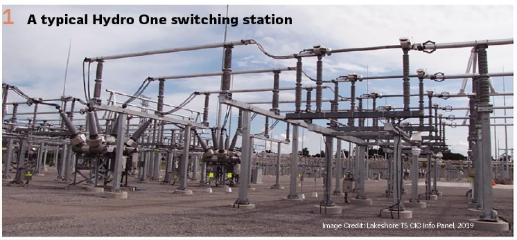
At the dawn of the 20th century, private companies were developing power generation facilities along the Niagara River, exploiting the bounty of hydroelectric potential in the southern region of Canada’s province of Ontario. In the interest of providing its constituents with a public utility, the government of Ontario passed the Power Commission Act in 1906, thereby forming the Hydro-Electric Power Commission of Ontario, which was renamed as Ontario Hydro in 1970. In the late 1980’s a move toward deregulated energy markets swept across North America; through the Energy Competition Act, 1998, Ontario Hydro was restructured into five entities to provide competitive electricity rates for consumers. One of these five entities, dealing with transmission and distribution, became Ontario Hydro Services Company (Ontario Hydro), the predecessor to the modern Hydro One. With close to a hundred years of history, Hydro One has had an extensive history of protecting transmission lines and improving its settings philosophy. (Figure 2).
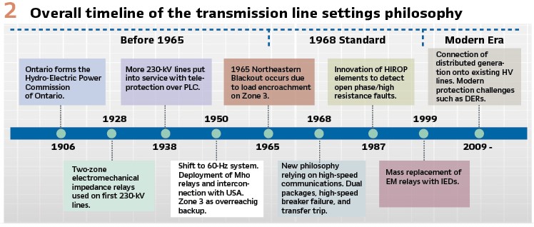
Before 1965
In the early 1900’s, the Hydro-Electric Power Commission of Ontario became one of the world’s first integrated public electric utilities. It completed the first 110-kV bulk electric power transmission lines to supply several municipalities in southwestern Ontario and by 1920, hydro accounted for more than 97% of total electricity production in Canada.
The first protective relays developed were electromechanical type. These were applied on the utility’s growing transmission network. It was in 1928 that the first 230-kV lines of the province were put into service at 25-Hz. The scheme for these lines employed balanced-beam impedance relays which were designed and manufactured in house. In this scheme, two sets of impedance relays were employed (one for phase and one for ground), supervised by directional overcurrent elements. To account for metering error in the instrument transformers, two tripping zones were used: an instantaneous underreaching Zone 1, and a time-delayed overreaching Zone 2 (acting also as a protection backup). Phase relays were yet unable to discriminate between phase-phase and three-phase faults and had to be set accordingly. Ground relays, prior to the development of zero-sequence compensation, were set based online impedance with a much-added reach for Zone 2.
Emerging from the Great Depression, in 1938, more 230-kV lines were put into service in southern Ontario. Communication media, in the form of power line carrier, were installed to support a permissive overreaching transfer trip scheme on these lines, increasing dependability. A decade later the grid began to standardize to a 60-Hz frequency, and a sweeping effort to replace the 25-Hz protection system began.
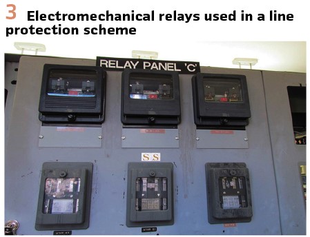
By 1950, the Mho relay had arrived as a superior alternative to the balanced-beam impedance relay. Mho relays with Zone 1 and Zone 2 backup became standard, expanding on the usage of communication-aided schemes for high-speed tripping. These included permissive overreaching transfer trip (POTT), directional comparison blocking (DCB), and phase comparison (Figure 3).
1968 Protection Standard
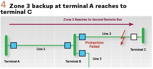
As the Hydro-Electric Power Commission of Ontario began interconnecting its 230-kV network with the United States for the purposes of creating the northeastern grid to improve reliability, constraints in Zone 2 as a conventional backup were revealed. To address this, Zone 3 relays (timed at 3 seconds) were introduced with a very high reach all the way over to the line ends of circuits adjacent to the remote terminal breaker. Consequently, the risk of load conditions encroaching into the phase Mho characteristic increased. (Figure 4).
This risk was unfortunately realized on a cold November day in 1965, when a line in the Niagara region was overloaded and a Zone 3 remote backup tripped. After the loss of the line, other loaded lines at the substation also tripped on Zone 3, leading to a cascading blackout that spilled into the northeastern United States, including New York City where restoration efforts took up to two days.
To address the security risk, blinders were added to the Zone 3 characteristic to block load encroachment. This solution was not without its limitations in an increasingly complex network. The 1965 blackout and its political repercussions served as an important juncture in the story of the utility’s protection philosophy, triggering new protection standards and an era where modern communications began to be used for remote end breaker failure. Protection would be duplicated in 2 packages, designated ‘A’ group and ‘B’ group – each identical in function, fully self-contained and independent of the other.
The availability of instantaneous overcurrent relays on the market, with faster high pickup/dropout ratios, allowed for the development of high-speed breaker failure protection that would replace the older Zone 3’s. A robust microwave telecommunications network was designed by the Relay and Communication Department to meet a 99.99% reliability objective resulting from the events of 1965. This channel facilitated the use of transfer trips, signals that trip the remote breakers, initiate their breaker failure protection, and initiate their automatic reclosure circuitry. Transfer trip channels were shared by breaker failure and line protection schemes.
Direct underreaching transfer trip (DUTT) via microwave or power line carrier (PLC) was embraced as a standard scheme for 230-kV lines. A local Zone 1 trip initiates breaker failure and automatic reclosure, and transfer trip is transmitted to the remote line end. Receival of a transfer trip signal from the remote end would initiate a local trip, breaker failure and automatic reclosure.
In a simple 2-terminal DUTT application, for a fault occurrence at 50% of the line where Zone 1’s overlap, the fault is cleared instantaneously. Near the line ends where only one Zone 1 sees the fault and transfer trips to the other end, the fault clearing time would take slightly more time for the channel delay.
DUTT offered high-speed tripping on the entirety of the line if the communication channels were healthy. However, if the remote end breaker or line disconnect switch is open it will fail. To provide an alternate instantaneous fault clearing approach, and address a potentially open remote end breaker, POTT or DCB schemes were set up concurrent to DUTT.
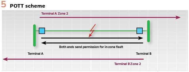
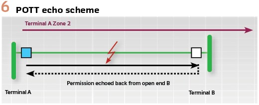
The POTT scheme via microwave was adopted as the standard for most 230-kV lines in southern Ontario. In the POTT scheme, if local Zone 2 (set to ~125% of line impedance) picks up, it will transmit a permissive signal to the remote line end. If it receives a permissive signal from the remote end, and it detects a fault, it will trip immediately. In addition, it will initiate breaker failure and automatic reclosure and send a transfer trip to the remote line end. Should the remote line end be open when the local end keys permission, the permissive signal would be echoed back to local. (Figures 5, 6).
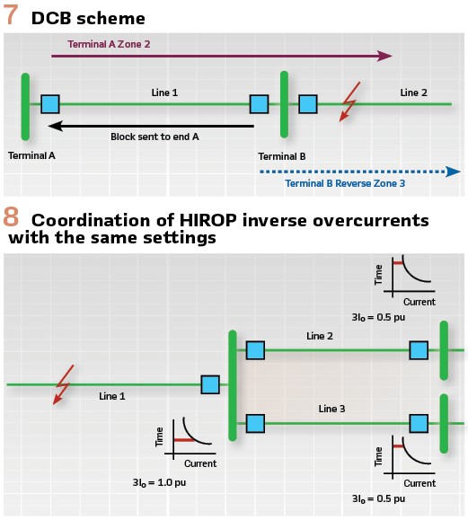
In the DCB scheme via either microwave or PLC, Zone 2 elements wait 50-ms for a blocking signal to be received from the remote end. If no block is received by the elapsed time, it will trip locally, initiating breaker failure and automatic reclosure, and send a transfer trip. If a block is received, the relay will not trip. If local Zone 3 reverse-facing elements pick up, it will transmit a blocking signal to the remote end. Zone 3 reach is set to the overreach of the remote Zone 2 of the neighboring system plus a margin (typically 10%) to ensure blocking of remote Zone 2 for out of zone faults (Figure 7).
The typical DCB coordination delay of 50-ms was chosen based on twice the assumed delay of microwave communication (20-ms), plus some margin. This mandatory timer makes POTT a slightly faster scheme, and thus the preferred scheme in southern Ontario during the era. However, due to the risk of the permissive signal not being transmitted over PLC, in areas where only PLC was available, the A group protection was POTT, and the B group was DCB.
Independent of the schemes, an overreaching Zone 2 will trip unconditionally after an extended time delay, although it will not trigger transfer trip or automatic reclosure. The intention of this behavior was to provide protection upon a total loss of communication channels. As a backup element, only to initiate if all other protective elements failed, the standard time delay was desired to exceed the remote breaker failure clearance time (with a margin) – a value selected to be at 400-ms.
High resistance open phase (HIROP)
In the early 1970s, the problem of high-impedance faults caught the attention of the public as well as that of protection engineers at the newly minted Ontario Hydro. The utility had a unique interest in the consequences of open phase due to the architecture of its system. While elsewhere, generation is typically spread out over a large geographic area and connected to the grid at multiple nodes, Ontario Hydro interfaces with large concentrations of generation found close to each other. This exposes a high amount of generation to the risk of being shaken off for a single open phase.
One of Ontario Hydro’s most innovative developments of this era was high resistance open phase (HIROP) protection (ANSI device code 97N), which served two functions: the detection of an open phase, and the detection of a high resistance fault.
Open phases frequently occur when one or two poles of a breaker/disconnect switch fail to open/close effectively. The sequence components of the currents will then circulate in the affected system in inverse proportion to their sequence impedances. The currents are in the magnitude of the load currents, depending on how large they were before the occurrence of the open phase; the element with the open phase would carry the most current.
In 1981, there was an open phase in a synchronizing circuit breaker in the switchyard at the Nanticoke coal generation station. The phase currents at the site of the open phase were high enough that they produced large zero-sequence currents flowing back into the grounded generator unit transformers – thereby tripping the transformer ground overcurrent relays and disconnecting all four 500-MW units. It became apparent that a simple open phase in a breaker or line disconnect switch could shake massive amounts of generation off the system.
The Ontario system is solidly grounded, such that zero-sequence current will flow in all cases (excluding radial lines). Furthermore, there was no line where an open phase would not result in at least twice as much zero-sequence current on the line with the open phase than on any other line in the system.
In view of these principles, it was decided in 1987 to implement inverse time zero-sequence measuring relays, set with the same pickup current, and time dial settings measuring the zero-sequence current of all system elements.
This would enable selective operation and isolation of the open phased element at the affected terminal since the relay at this terminal would operate first.
Coordination was achieved by having all relays use the exact same pickup, time dial and curve. The minimum pickup of the overcurrent was based on a balance between the maximum natural unbalance current on the transmission lines, and the zero-sequence current as it is directly related to the pre-open phase load current. As some 500-kV lines had a natural unbalance as high as 175-A, it was decided to use a pickup of 360-A (twice the unbalance with some margin) for all relays. A time dial of 0.5 and the IEC Curve ‘A’ ensured the open phase protection would never operate before line protection.
These open phase detection elements would also be able to provide coordination for low level high resistance ground faults.
Yet for high magnitude high resistance ground faults that could not be detected by the ground distance relays, coordination could not be ensured (Figure 8).
To address this, a high set instantaneous ground overcurrent element was included in the open phase protection on lines where they would not trip for remote end faults. For shorter lines, it had to be included as an operating element in the DCB/POTT scheme. In these cases, the overcurrent was directional and delayed by 120-ms, to allow for current reversals when one breaker tripped before the other. A 2-kA pickup setting was selected because it would detect essentially any forward fault, and lines where the tapped transformer inrush current could exceed 1-kA could be energized. This incurred an additional cost for directional relays, and so was only applied on short lines.
Hydro One and the Modern Era (1998 Until today)
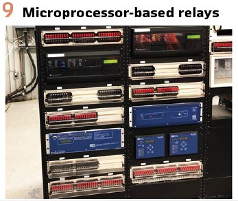
In the latter half of the 20th century, protective relays rapidly evolved, leveraging powerful microprocessor technology. As the newly formed Hydro One, a formal program was developed to replace end-of-life solid state and electromechanical devices with microprocessor-based ones, called Intelligent Electronic Devices (IEDs). In addition, the older microwave communication system was gradually replaced with high-speed digital systems using microwave or fiber optics. (Figure 9).
In adopting IEDs, Hydro One made a conscious decision to disable native relay logic in favor of programming its own unique logic which matched the existing setting philosophy. In addition, consistent input and output signals were used, meaning that regardless of the relay model, the wiring and operation remained standard.
IEDs brought innumerable benefits for the design and installation of protection systems. A single IED could replace the functions of several electromechanical relays that formerly took up more space on the rack mount.
With IEDs in 1999, directional ground instantaneous overcurrent elements could be included in the POTT/DCB schemes at no additional cost. This addressed the limitation with HIROP and meant that all high resistance ground faults down to only 2-kA could be detected. As a result, the high set instantaneous elements that were in place on longer lines were phased out.
In 2009, Hydro One began to connect distributed generation onto existing high voltage lines, adding a layer of complexity from a protection perspective. Prior to this moment, generation would supply energy to a major bus at a terminal station. Now, generators directly supplied energy onto long transmission lines across multiple locations.
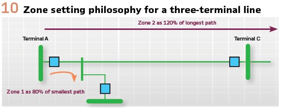
In two-terminal applications, the setting of Zone 1 at 80% and Zone 2 at 120% of line impedance is straightforward. However, with multi-terminal lines, this line impedance must be defined as the path to one of the remote terminals. Zone 1 reach would now need to not exceed 80% of the shortest path to a remote terminal to ensure that there was no chance Zone 1 would trip for an out of zone fault. Zone 2 reach, on the other hand, would need to be set to 120% of the longest path to a remote terminal, to guarantee complete coverage of the line for local backup as well as teleprotection schemes. (Figure 10).
The logic of POTT and DCB would also require adjustment to accommodate the terminals involved in the scheme. For POTT, a permissive signal would need to be received from all remote ends before initiating local tripping to ensure that the fault is seen by all ends and was therefore in zone (AND-gate). For DCB, if a blocked signal was received from any line end, it should then inhibit local tripping as the Zone 2 could be overreaching any one of the remote terminals (OR-gate).
Future
Rapidly evolving technologies, customer needs, and global commitments to reduce greenhouse gas emissions have transformed the energy industry in recent years. Increased deployment of distributed energy resources (DERs), increased share of DC electricity transmission, and continuous reduction of conventional synchronous generation pose a wide range of challenges to existing power systems, including the provision of dependable and secure protection.
The protection field is undergoing major transitions, such as the implementation of IEC 61850 and the protection of inertia-less/deprived systems. Though costly, effective philosophies such as transfer trip have enabled protection engineers to overcome many of these modern challenges.
In 2009, Hydro One released the Distributed Generation Technical Interconnection Requirements (TIR). Taking into consideration the IEEE 1547 standard, other industry standards, and Hydro One’s business practices, the document guides customers below 50-kV on scheme configuration, isolation, protection, and control requirements at the point of interconnection.
Most local distribution companies in Ontario have adopted its principles. These requirements play an important role in protecting DERs, where protections cannot determine if undervoltages are due to an in-zone fault or transients elsewhere in the system. The implementation of transfer trip with DERs allows faults to be cleared in these scenarios in a timely manner without adverse effects on a larger base of customers.
As demand for distributed generation increases, Hydro One will continue to research innovative ways to relax transfer trip requirements based on acceptable risk, such as utilizing controlled signals through the Distribution Management System for energy storage and smaller-size inverter-based generators. Automated tools can now be used to verify relay settings, perform wide-area coordination studies, and validate protection system compliance.
Though tools and approaches to developing the settings philosophy will continue to change, our commitment to safety and reliability will always remain.
Acknowledgements: The backbone of this article was formed from the exhaustive work of John Ciufo & Aaron Cooperberg. In addition, the authors would like to acknowledge the countless other engineering experts whose efforts have contributed to the innovation of Hydro One.
Disclaimer: Any opinions expressed in this article are those of the authors and do not necessarily reflect the views and opinions of Hydro One. Hydro One will not be liable or be held responsible for any consequences of the use of, or reliance on the information contained in this article.
Biographies:

Daniyal Qureshi is a Protection & Control Officer at Hydro One Networks Inc. He specializes in protection system modelling in industry-standard software, studies for the purposes of compliance, and the development of automated solutions for analysis and reporting. Through Daniyal’s prior experience as a consultant, he has contributed to relay coordination and sensitivity evaluation tools for numerous utilities across North America. Daniyal regularly authors conference papers and holds a Bachelor of Applied Science degree in Electrical Engineering from the University of Toronto. Daniyal loves reading and has a passion for Classical languages, world history and paleontology. In his spare time, he enjoys horse-riding, travelling, and writing.

Pankaj Sharma (Bachelor, Electrical Engineering) is licensed professional engineer in the province of Ontario, Canada. He works as Sr. Manager, Protection & Control Engineering in Hydro One. After graduation Mr. Sharma worked 15 years in Gujarat Electricity Board in India. Mr. Sharma joined Hydro One in 2006, worked in Asset Management, Operations and Engineering departments. At present his team delivers designs of Protection, Control and Metering for Transmission & Stations.

Suzana Arbana P.Eng., is a senior electrical engineer with over 25 years of expertise in protection, control and SCADA design of power generation, EHV/HV transmission and distribution systems. Her design experience includes utility, commercial and industrial sectors. She has a degree in Electrical Engineering Power System from Polytechnic University of Tirana Albania. Currently she works as the Manager for P&C Engineering at Hydro One where she leads a team of 25 design engineers.