by Chris Bolton, Tariq Rahman, Daniel Dietmeyer, San Diego Gas & Electric Company, and Eric A. Udren, Quanta Technology, LLC, USA
Utilities around the world are facing unprecedented levels of fire risk from routine electrical faults and failures in transmission and distribution system lines and equipment. Major fires in recent years have elevated public awareness. San Diego Gas & Electric Company (SDG&E) has been implementing innovative new technologies and strategies to reduce the risk. There is not a single fix – SDG&E pursues a variety of apparatus upgrading programs, real-time situational awareness, operational and event responses, and development of protection and control (P&C) equipment and methods.
This article summarizes SDG&E’s broad range of strategies for reducing fire risk but focuses on adaptive distribution fault detection and tripping designs, and on new systems for high-speed protection against the impacts of conductor breaks.
When transmission or distribution line conductors fail and fall to the ground, the resulting high- impedance arcing fault may be difficult for relays to detect yet can ignite dry vegetation or create an electrical hazard in the vicinity of the live downed conductor. SDG&E pioneered development of a distribution falling conductor protection (DFCP) system that collects streaming synchrophasor measurements from along a distribution circuit and can detect a break and open adjacent breakers or switches by the time the overhead conductors have fallen about one meter. The broken conductor ends land dead; there is no arcing fault or public risk. SDG&E first deployed trial DFCP in 2015; 150 deployments are now in progress in high fire risk areas.
In 2019-2022, SDG&E carried out a development program for transmission system falling conductor protection (TFCP) systems. One is based on synchrophasor voltage and current measurements from two- or three-line terminals – data already being gathered for engineering and operational situational awareness client systems. This scheme is further enhanced with a sensitive backup ground differential protection scheme for very high impedance faults triggered by tree contact before or without a conductor break; this protective scheme demonstrates prospects for expanding backup fault protection with schemes based on PMU data. Another scheme uses transmission line relay measurements directly for TFCP protection.
Grid Hardening and Operating Adaptations
SDG&E has developed a broad fire safety enhancement program combining fundamental common-sense upgrading efforts to reduce root causes of risk with developments of new technologies to detect impending or immediate risks at specific locations. The company has invested for over a decade in the risk assessment and mitigation phase of its wildfire risk control and mitigation plan.
Operational planning begins with an assessment of the cross-functional activities that impact wildfire risk reduction. These include:
- Climate change adaptation – bolstering system resilience; reducing greenhouse gas emissions
- Asset management program including inspection and fleet assessment to identify and repair apparatus or facilities for reduction of fire risk
- Emergency preparedness and response, including proactive response to potential risk situations and post-event analysis of response effectiveness
- Safety management systems, including communications systems and comprehensive training of company teams on safety issues and procedures
- Workforce training, qualification, and planning for all risk mitigation and response activities
- Records management for continuing internal and regulatory tracking
Risk Bowtie
The left side of the Figure 2 risk bowtie lists the drivers or triggers for wildfires. The common result from all these 10 driver categories is that any of them can ignite a wildfire. This is illustrated by the central red disk in the risk bowtie configuration.
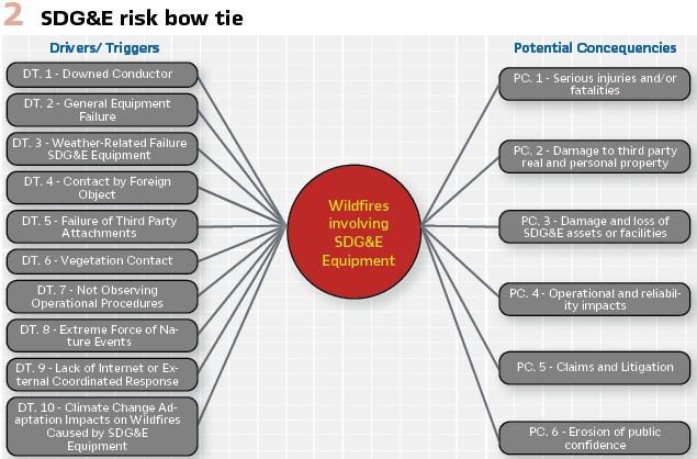
Should a fire occur, the consequences shown on the right are independent of the triggering event. In the January-February 2022 issue of IEEE Power and Energy Magazine, the article, Managing Wildfire Risks by Udren, Bolton, Dietmeyer, Rahman, and Flores-Castro presents details of extensive operational programs that can mitigate the impact of a fire ignition, and risk scoring systems that focus investments to get the optimum risk reduction outcome. The focus of this article, however, is technical developments to reduce the risk of ignition from driver/triggers DT.1, DT.4, DT.5, and DT.6.
Strategies in Application of Conventional Fault Protection Relays
For distribution fault protection, SDG&E uses two adaptations:
Sensitive Relay Profile (SRP) settings – With conventional time-overcurrent protection settings, it may take seconds to clear a fault. A special group or profile of relay or recloser protection sensitivity and tripping time settings can be engaged by distribution operations at times of high fire risk. The setpoints are set as sensitively as possible without tripping for normal load conditions and will clear a fault in less than 4 power cycles or 70 ms. To achieve optimum speed and sensitivity, historical five-year loading profiles on individual devices and circuits are gathered via SCADA data communications from each recloser. SDG&E has developed an automated data processing tool that analyzes the loading history of every device in high fire risk districts to flag SRP setpoints that need reverification and updating of operator decision criteria.
When SDG&E meteorologists forecast elevated or extreme fire risk weather conditions, operators remotely switch a pre-defined list of reclosers to SRP profile in advance. These SRP settings do not coordinate with other protective devices such as fuses or other reclosers further down the circuit– faults will trigger uncoordinated tripping of multiple devices and will de-energize larger sections of the feeder, requiring more extensive patrols to locate the problem and ensure that the circuit is clear for re-energization. In service experience, SRP has prevented fire ignitions, outweighing the loss of protection coordination and larger extent of outages.
Sensitive Ground Fault (SGF) protection – Some distribution faults cannot be detected by relays or reclosers using standard ground overcurrent protection settings. The standard settings are typically high enough to avoid tripping for normal phase load imbalances, which look to the relays and reclosers like low-current ground faults of the same magnitude as the imbalance. SGF replaces standard ground current magnitude trip settings with values that are customized for each device, set just above the normal unbalance seen by that device.
Just as with SRP, setting SGF protection requires constant review and adjustment of individual protection settings in comparison to field load data history to avoid trips for load imbalance. Specially developed analytic tools evaluate the actual range of load-induced current imbalance for each relay or recloser reporting load profiles, using measurements collected by SCADA – the same loading data and tool systems used to determine annual baselines for SRP settings before each fire season. With this device-customized load imbalance profile, each device can be set just above its worst normal imbalance level with minimized risk of false tripping for normal loading. On well- balanced circuits, the setting can be far more sensitive than standardized settings.
SDG&E applies SGF settings year-round. As with conventional time-overcurrent protection, SGF is time-coordinated by setting a half-second delay interval between tripping times of reclosers along a circuit. This time delay minimizes the reliability impact by isolating a smaller section of the circuit when a fault occurs, and thus enables the full-time use of SGF.
Distribution Falling Conductor Protection (DFCP)
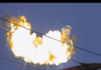
The purpose of FCP is to detect an energized conductor that has broken and to de-energize it before it strikes the ground, thereby eliminating the risk of fire ignition or public exposure to live conductors. SDG&E and other utilities experience such conductor breaks even with vigorous circuit-hardening programs. An SDG&E project team invented and patented the concept and scheme of FCP while developing new synchrophasor-based distribution circuit monitoring and protection system technology.
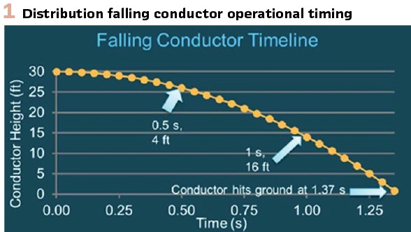
Figure 1 shows the time sequence for a broken overhead distribution conductor falling from a height of 30 feet (9 m). Accelerating from the moment of the break, one or both ends reach the ground 1.37 s later. The FCP scheme can detect the break from circuit voltage signatures and issue trip commands so that the affected section is de-energized 200 to 500 ms after the break–when the conductors have fallen only a few feet, or about 1 meter.
Scheme components: The system utilizes PMU-enabled protection and control intelligent electronic devices (IEDs) along the distribution circuit, an Ethernet circuit-area high-speed data communications system, and a substation- based phasor data concentrator (PDC) that streams collected synchrophasor streams to an adjacent real- time automation controller.
The controller holistically processes all the circuit measurements with algorithms developed by the SDG&E project team to detect the break between two measurement locations. The controller can send trip commands to the circuit protection IEDs on circuit switching devices that can isolate the break, typically within 100 milliseconds of detection.
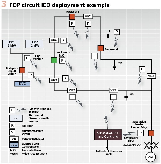
Figure 3 shows a typical distribution circuit radiating from a distribution substation with arrays of circuit IEDs communicating with the substation-based scheme controller.
Substation and Circuit IEDs: The participating IEDs include the protective relays at substation circuit breakers, recloser controllers, and voltage monitors along the circuit. Commercially available IEDs are capable of streaming synchrophasor voltage and current measurements via high-speed communications at a rate of 30 or 60 synchrophasor sets per second, in addition to conventional protection, control, and SCADA functions. Wideband Ethernet radio systems or private cellular networks convey measurement and control data streams between circuit locations and the substation.
The substation controller analyzes the patterns of negative-sequence and zero-sequence voltage magnitudes and angles holistically across the circuit to its measurement end points. If the controller detects the pattern caused by a conductor break, it sends high-speed tripping commands to circuit switching devices over the same communications network that is used to collect the synchrophasor measurements used by the algorithms. In real-time digital simulator (RTDS®) laboratory testing, the DFCP system has been essentially 100% effective, even with inverter-based PV sources on the feeder, and with malfunctions of circuit apparatus like misaligned voltage regulators.
Transmission Falling Conductor Protection (TFCP) System
In 2019-22, SDG&E built on DFCP experience to develop two TFCP systems. One scheme is based on measurements made within special versions of transmission line protective relay types in use today. The scheme discussed in the following is based on real-time processing of the PMU data streams like those already being collected from ubiquitous transmission substation relay-PMUs communicating synchronized measurements to the SDG&E wide-area situational awareness (WASA) control center system at 60 frames per second. The TFCP algorithms are conceived to be programmed in client software in a control center computer networked to the phasor data concentrator (PDC). This wide-area application protects the entire transmission grid from falling conductor issues, as it adds no new equipment at substations.
The entire scheme of PMUs, communications, servers, and outbound network tripping channels are self-monitoring and thus bring no additional maintenance requirements for the new protection capability.
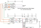
However, for the first lab development and field trials, the project team implemented the same processing algorithms on a real-time controller that can be configured in the RTDS laboratory, and then installed in a substation with the existing relay-PMUs. Figure 4 shows a typical TFCP system configuration for a two-terminal transmission line with the real-time controllers used for development.
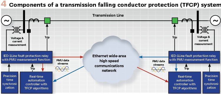
Figure 1 showed the timeline for a falling distribution conductor from 30 feet or 9 m. A broken overhead transmission conductor 60 feet (18 m) in the air takes even longer – almost 2 seconds to reach the ground. With PMU measurements and detection algorithms, substation controllers and relays (or the eventual central controller platform) can trip line terminal breakers by the time the failed conductor has fallen only about 1 meter.
The transmission FCP measurement system and algorithms are fundamentally different from distribution FCP, depending mostly on circuit current rather than voltage measurements. This TFCP method uses synchronized current comparisons from the line terminal PMU data streams to observe pre-event load flows and rapidly detect conductor breaks, even on multiterminal lines. Charging currents into the broken conductor sections from each end help to locate the break for rapid field crew deployment. The TFCP system can detect and de-energize the line in less than 400 ms for falling conductor events.
Along with the FCP algorithms, the TFCP scheme includes high-sensitivity ground fault detection to trip within a few power cycles for non-break fire-risk events like tree branches falling on or blowing into lines from outside the vegetation-management right-of-way, as described further below.
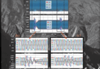
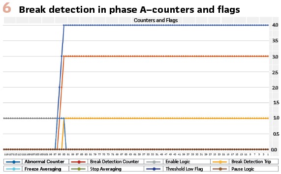
TFCP Testing: The synchrophasor based TFCP scheme was extensively tested on a model of a section of the SDG&E 69 kV transmission system, programmed on RTDS arrays in the SDG&E Integrated Technology Facility (ITF) laboratory. In laboratory hardware-in-the-loop (HIL) tests, the TFCP solution has demonstrated its tripping speed, dependability, and avoidance of false tripping for a host of break simulations, faults, and operating events on the protected line and the adjacent power system. The TFCP controllers capture records of PMU data surrounding an apparent break or ground fault in Excel® format for post-mortem plotting of algorithm performance and event replay using PC tools as shown in examples below.
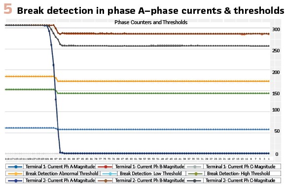
Figures 5 and 6 show TFCP operation for a simulated break of a 69 kV line carrying load. Each trace dot is a synchronized measurement frame time of one 60-Hz cycle or 16.7 ms. The RTDS model of the break event includes simulation of the series arc that may occur as the broken load-carrying conductor ends separate. Automation controller logic checks for normal pre-break line operation and other conditions to distinguish a conductor break from other types of events. Break detection is confirmed within 2 to 3 data frames, or less than 50 ms.
TFCP works on lines with single phase conductors – this covers the overwhelming majority of HV transmission lines, including those in high fire risk areas. It is not effective for EHV bundled-conductor lines if just one conductor in the bundle breaks – there is no current change until a ground fault occurs. These EHV lines are not the major source of fire ignition risk with robust construction, fewer circuit miles, and wider and more carefully maintained rights of way.
PMU-based 87LN Fault Detection
TFCP is not effective if a tree branch contacts a live conductor. However, the same filtered and stable PMU current value streams used for WASA and TFCP can be integrated in a ground current differential or 87LN calculation, in the same computing platform used for TFCP. Separate current differential algorithms using PMU data detect ground faults, even with thousands of ohms of resistance, and issue trip commands within a similar detection time frame to TFCP. Sensitivity may be far better than that of high-speed line relays.
87LN protection comprises a summation of PMU currents from line terminal phase currents, with additional supervising and sequencing logic for security during switching and startup. The net ground current sum is close to zero during normal line operation. Familiar zero-sequence harmonic distortion is suppressed in PMU data, at the cost of 2-3 cycles of filtering delay. CT errors create small summation currents which are stable and can be compensated. Tapped loads from delta-wye connected transformers do not impact protection measurement. The scheme can work for multi-terminal lines, as for TFCP.
The operating range is restricted to fault currents below about 2 p.u. – high-current faults that could saturate CTs and cause misoperation of differential schemes are well handled by conventional line relays. A percentage-differential characteristic not needed – the design uses load-adjusted pickup sensitivity which has proven effective in testing.
RTDS® tests have shown reliable tripping for faults of 3000 to 5000 ohms without external fault tripping risk. Field experience may support even more sensitive decision thresholds. The developers are also working with new detection enhancement methods that may bring even higher sensitivity.
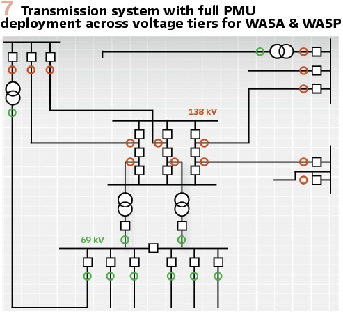
Wide-area Fault and Swing Protection (WASP): For utilities deploying WASA or WAMPAC with high-density PMU measurements across the transmission grid as in the Figure 7 example, the 87LN sensitive ground fault function is a convincing demonstration of sensitive, secure PMU-based backup fault protection from synchrophasor streams. Strong test results for 87LN in TFCP development show how a combination of this ground fault detection and 87L phase protection can be applied in a WASP surgically selective backup fault protection scheme. CIGRÉ Paper B5-112 of the 2014 General Session, Paris, explains the concept; it also explains how voltage synchrophasors can be used for swing and stability protection for events which current differential relays ignore.
WASP is slower than primary relaying (3 cycles or more) but much faster than remote distance backup. It comprises a completely independent, self-monitoring backup protection system with no critical reach settings. Unlike distance relays, WASP trips dependably with weak or variable infeed from IBR or other DER. It surgically removes faults left by failed relays or stuck breakers, tripping only the breakers required to isolate the specific protection malfunction. Non-communicating backup-zone distance relay zones can be left in service as a safety net – they will always lag WASP. This safety net role brings relief from today’s critical backup setting studies and updates.
Conclusion: SDG&E has confronted wildfire risks for over a decade with operating and situational awareness innovations, organizational preparedness, hardening of infrastructure, and sustained technical innovation.
Innovations include invention of distribution and transmission falling conductor protection (DFCP and TFCP) schemes based on PMU measurements.
SDG&E is deploying DFCP on 150 circuits in high fire risk areas. TFCP has now been developed to operate from existing PMU streams from relays supporting the control center WASA system. Tests show dependable tripping performance for conductor breaks under the full range of circuit operating conditions.
The TFCP implementation is augmented with an 87LN ground differential protective function that can trip the line for non-break events of tree contact with fault resistance of up to 5000 ohms, with further sensitivity developments ongoing. Demonstrated 87LN performance sets the stage for development of backup wide-area system protection (WASP) based on the same PMU infrastructure and measurements.
Biographies:

Christopher Bolton is the Construction and Operations Manager for the North-East district of SDG&E, where he has worked since 2011. He has held various positions in the utility space, including substation engineering, capital projects, substation technical analysis and support, system protection maintenance, and recently as the manager of system protection, automation, and control engineering. Christopher graduated with a Bachelor of Science in Electrical Engineering from California State Polytechnic University-Pomona and is a licensed professional engineer in California.

Tariq Rahman – P. E. is a Principal Engineer in the Electric Engineering Department at San Diego Gas & Electric Company (SDG&E®), California. He obtained his BSEE in 1980, and MSEE in 1985. Tariq has 30+ years of experience in working with electric utility industry in Electric Grid Control Room Operations, Generation Planning, and System Protection & Control Engineering. Tariq has been leading SDG&E’s Transmission Synchrophasor-based Wide Area Situational Awareness (WASA) System project since 2010. In 2017 his effort and the accomplishment of SDG&E has earned him the NASPI “Synchrophasor Technology Champion” award, and SDG&E the “NASPI 2017 Outstanding Utility” award.

Daniel Dietmeyer is Lead for the Transmission Protection and Automation Team in SDG&E System Protection and Control Engineering. He managed major projects in Electric Grid Operations including the Falling Conductor Protection program and Transmission Control Room Rebuild. Dan served in the US Marine Corps and is President of the SDG&E VALOR veterans’ organization he co-founded. He holds BSEE and MSEE degrees, numerous professional certificates, and is a licensed Professional Engineer in California.

Eric Udren is Executive Advisor with Quanta Technology. He has a five-decade career in design and application of protective relaying, substation control, communications, and synchrophasors in T&D applications. He is Life Fellow of IEEE and active leader in IEEE PES PSRC and Communications and Cybersecurity Committees, IEC TC 95 relaying standards, IEC 61850, and NERC. He was Industry Guru in the September 2016 issue of PACworld and is a frequent contributor. In 2019, he was elected to the US National Academy of Engineering.