by Benjamin Moesslang, illwerkevkw vkw AG, Austria, Marco Bertolini, Vorarlberger Energienetze GmbH, Austria, and Jochen Heimann, Amprion GmbH, Germany
The protection system of a four-terminal transmission line involves a high degree of complexity. Many devices, including protection and communication devices, are involved in providing optimal protection to the line in operation. The level of complexity is further increased when, as in the case described in this article, three companies with three different protection philosophies come together to protect such a line. This article describes the commissioning test of the line protection of a four-terminal line. During the test, the responsible protection engineers used a system-based protection test to gain a detailed insight into the behavior of the protection system.
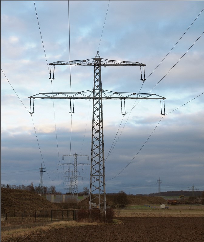
The protected line is a 220 kV line between Austria and Germany. This line is part of the historically significant North-South line, which originally ran between Brauweiler in Germany and the power plants of illwerke vkw AG in Montafon, Austria. The North-South line is one of the oldest commercial electricity links in the world and was built in the 1920s by RWE AG to transport electricity generated in Vorarlberg and the southern Black Forest to what was then Germany’s industrial center, the Ruhr region. It was one of the world’s first commercial power links designed for a voltage level of 380 kV. To date, some line sections have been converted from the original lower voltage levels to 380 kV, but the section discussed in this article continues to operate at 220 kV.
The three companies involved in the operation of this line section, which is more than 200 km long, are: Amprion GmbH on the German side and Vorarlberger Energienetze GmbH and illwerke vkw AG on the Austrian side. The line has four ends, with two in Germany (SSG1 and SSG2) and two in Austria (SSA1 and SSA2). After the new construction of a substation in Germany (SSG2) with the erection of a transformer bank, a new protection concept was required. The previous protection concept was extended to include differential protection in the main protection to increase availability.
Protection System
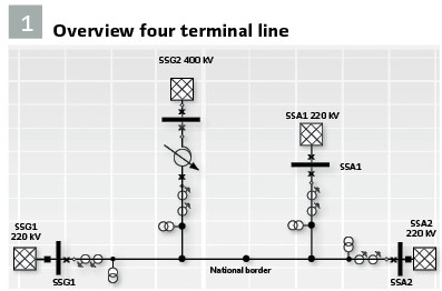
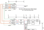
The Main 1 System consists of four Siemens 7SL87 multifunction protection devices and the Main 2 System consists of three Schneider P437 distance protection devices and one P433 (SSA2). Figure 1 shows an overview of the line.
The multifunction devices of the Main 1 System use two protection principles. The first of these protection principles is line differential protection, which allows the entire line to be selectively protected instantaneously. The four devices of the Main 1 System are interconnected in a ring topology with a protection interface enabling function preservation in case of a failure of a part of this communication line. The second protection principle of the Main 1 System, operated in parallel, is a distance protection with permissive overreach transfer tripping (POTT).
The distance protection devices of the Main 2 System work with the same POTT scheme and share the same communication links as the devices of the Main 1 System. This means that there is only one transmit and one receive signal per end, which is used equally by the Main 1 and Main 2 systems. It should be mentioned that due to different protection philosophies and the integration of new protection devices in the inventory, the devices in SSG1 and SSG2 transmit a permissive signal with the tripping of each zone and the devices in SSA1 and SSA2 transmit only with the tripping of the forward zones. The received signals of each end are ORed and release the overreaching zone Z1B, for both the Main 1 and Main 2 systems. The reach of zone Z1 of each end extends to just before the next station, zone Z1B overreaches beyond the station furthest away.
For single-pole faults, the devices of the Main 1 System, as well as the P437 devices of the Main 2 System, perform an automatic reclosure (AR). The P433 in SSA2 cannot trigger single-pole and must therefore not intervene in the AR cycle of the other devices. Therefore, the AR was not parameterized in the P433 and the tripping times of the corresponding zones were selected in such a way that they would not cause a three-pole tripping in case of a single-pole fault before the other devices had the possibility of an AR cycle. With the following tests the correct behavior of the AR could be verified.
In the event of failure of the low voltage-side circuit breaker (CB) on the phase-shifting transformer in SSG2, a Schneider P132 protective device takes over the CB failure protection. The inter-tripping of the CBs works via the protection interface of the line differential protection; in addition, a transmit signal is sent which activates the overreach zones in the other protection devices.
A total of twelve binary signal transmitters and 14 communication modules were installed for communication between the ends. The protection interface signals and the communication for the transfer trip are routed via separate communication links.
Methodology and Phases of the Test
For the commissioning of the new protection system, the responsible protection engineers in Germany and Austria used a system-based, end-to-end test of the entire protection system, which enables significantly more comprehensive scenario coverage than other methods. In system-based testing, a transient network simulation calculates realistic fault quantities which are then output by the test sets. The test technology used allows all test devices in all stations to be controlled simultaneously from just one PC, so that all eight-line protection devices can be subjected to synchronous test quantities at the same time. This ensures that the protection system consisting of the Main 1 and Main 2 systems can protect the line in all operating states and that it remains stable for all other cases.
The commissioning test of the protection system consisted of four different phases:
1. Testing of the POTT scheme and protection interface links
2. Stand-alone testing of each individual protection device
3. System-based testing of the entire protection system
4. Test of the entire protection system with live tripping
In the first test phase, the newly installed communication devices were tested for function. For this purpose, test signals were fed in at all ends and measured so that it could be ensured that communication via the communication links was functioning. This test of the communication links was carried out simultaneously at all ends and coordinated by means of video conferencing.
While the line had been taken out of service for modifications of the primary equipment, the new protection devices could be installed, and the stand-alone tests carried out at the line ends. Each company tested at its ends according to its own test specifications, such as testing the instrument transformers and tripping circuits and the active protection functions of the individual protection relays with time grading and AR function, as well as switch-onto-fault (SOTF).
In the third phase, the system-based test was performed. For this purpose, all protection devices of the systems Main 1 and Main 2 were tested at the same time. This way, the correct interaction of all devices of the systems Main 1 and Main 2 could be validated simultaneously in the same way as it is intended in actual operation for the various possible fault cases.
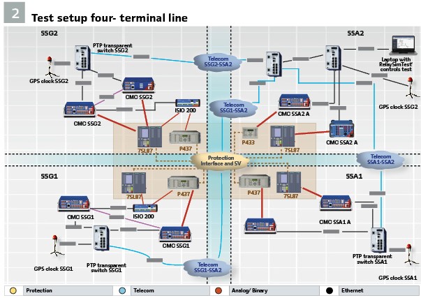
Figure 2 shows the test setup. Two test devices were used at each end so that each protection device could be tested with independent current and voltage triples. In addition to the analog signals, some binary signals were also wired. These were, for each protection device, the phase-selective trip signals, the three phase CLOSE command, a device Start signal, and the send and receive signals. The simulation in the test software provided CB auxiliary contacts (52 a/b) to the protection device in addition to the analog signals. A binary output on the test device in SSG2 was used to trigger the CB failure protection. Binary outputs were also wired for testing the signal comparison run times.
For the execution of the test shots, the test devices must be synchronized in time. For this purpose, GPS-controlled time references were used, which provide a very accurate time to the test devices by means of PTP. At each end, all test devices were connected in a local network with a PTP transparent switch. An additional switch was positioned in SSA2, which acted as a communication switch between the four ends. The control of the test devices was managed with a specially set up network. For this purpose, the telecom departments of the companies set up a direct Layer 2 connection between SSG2 and SSA2, SSG1 and SSA2, and SSA1 and SSA2 via existing communication channels. With the central switch in SSA2, it was now possible to create a separate overall network for testing. The testing software would also have offered the possibility of controlling the locally distributed testing devices by means of a cloud connection, but this was not possible due to the IT security regulations of the companies involved. The test was controlled via a PC in SSA2. This PC also shared the screen in a video conference, so that all the people involved could follow the test live and problems could be rectified immediately.
Two days before the actual test, a dry run was performed, during which the test hardware was set up, wired, configured and assigned IP addresses. This ensured the correct functioning of the test setup, including the synchronization of all test devices before the actual test. This meant that the protection technicians could concentrate fully on the test on the day of the test. The synchronization of the test devices proved to be problematic, as two switches distributed the local PTP time signal to the other ends via the network. As a result, the test devices could not find a reliable PTP time to synchronize. This problem was fixed by blocking the port on the switches that were responsible for the connection between the stations and SSA2 for PTP. Now each end had its own reliable PTP signal available. The fixed assignment of IP addresses in advance now turned out to be a good decision, as it was quite easy to access the required device.
Test
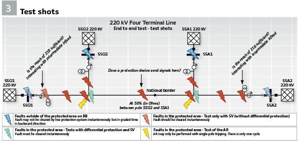
The test cases were planned and prepared in advance. The type and number of these were designed in such a way that good test coverage of all subareas was possible within a single test day (see Figure 3). Thanks to these preparations, testing could be started immediately on the day of the test.
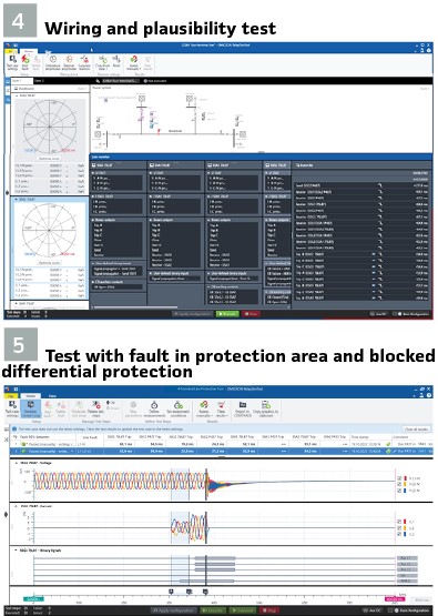
The first test performed was the wiring and plausibility test. This involved checking whether the test devices were correctly connected to the protection system and whether the protection system itself was functioning. Figure 4 shows a snapshot of this test case. The values calculated by the simulation and fed in by the test devices were compared with the displays of the protection devices. A fault was also simulated to verify that the protection system was operating as expected based on the binary monitor in the event list. After ensuring that the protection system was ready for operation, the actual test could be started.
In order to be able to evaluate the measured times correctly for the tests of the POTT scheme, the propagation times of the transmitted signals were measured. For this purpose, a binary trigger signal was output via a binary output which was connected to the inputs of the binary signal transmitters. In this way, the time between transmission and reception could be measured and thus the signal propagation times determined. It turned out that the parameters for the POTT scheme on one protection device had been set to an incorrect procedure. After correcting this setting error, the test could be continued.
The next group of tests were the stability tests. Here, the energization of the line was simulated to ensure that charging currents may not lead to a trip; but also faults which lie outside of the protected area. The latter must not trigger a trip with the differential protection but must be detected by the distance protection and cleared at a given time according to the set time grading. These tests showed that the protection system behaves as expected.
Test cases with faults in the protected area were divided into tests with active and with blocked differential protection.
The faults colored green in Figure 3 correspond to the fault locations of the test cases with active differential protection. In addition to the fault location, the fault loop was also varied. However, the protection engineers also limited the fault loops to a representative minimum (A-N, A-B-C) so as not to unnecessarily extend the test duration. This test also showed that the protection system responded as expected and was able to clear the faults instantaneously.
Since the line has four ends and powerful infeeds, the intermediate infeed effect is clearly apparent. For this reason, test cases were deliberately carried out with deactivated differential protection so that it could be checked whether faults could be cleared quickly and selectively even with blocked differential protection. For this purpose, the corresponding fiber optic cables were simply disconnected from the respective protection device.
The faults colored red in Figure 3 correspond to the fault locations of the test cases with blocked differential protection. The fault loops were selected the same way as for the test with active differential protection. For these test cases, the Iterative Closed Loop function of the test software was used. This made it possible to realistically record the extended tripping times due to the influence of the intermediate infeed.
The intermediate infeed effect means that the fault impedance cannot be correctly measured by some protection relays, because infeed currents that are between the fault and the measuring location raise the measured voltage, making the fault location appear further away. Those protection devices that do not have an intermediate infeed between them and the fault can correctly measure the fault location and thus trip in the correct zone with the correct time. After this intermediate infeed is removed through tripping, the next protective device can correctly measure the impedance and trip.
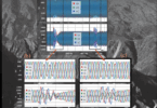
With several infeeding ends, the time until the line was de-energized increased by up to 70 ms compared to the clearing times with differential protection. Figure 5 shows such a test case.
The Iterative Closed Loop function was also used for testing the AR function with active differential protection. The faults colored yellow in Figure 3 correspond to the fault locations for these tests. Unsuccessful and then successful AR cycles were simulated in the test cases. Testing of successful AR showed that for self-clearing single-pole faults, the line is successfully reconnected.
Unfortunately, the unsuccessful AR could not be tested. Presumably, the jitter of the many signals led to overlaps and thus to inconsistent behavior for the test system, which is contrary to the deterministic sequence of the test.
A detailed analysis of the test software log files was not performed in order not to delay the rest of the test and to be able to complete it successfully. The stand-alone tests showed that the unsuccessful AR cycle works per se.
The last test was the test of the circuit breaker (CB) inter-tripping by the CB failure protection in SSG2. Analogous to the test of the signal propagation times, here too a binary trigger was applied via a binary output to the CB failure protection input on the protection device in SSG2, thus triggering the CB failure protection. In this test case, the time between the CB failure protection trip signal and the opening of the circuit breakers at the other ends was measured.
Two days after the system-based test described above, the final phase of commissioning took place with live circuit breakers, during which the inter-tripping of the remote circuit breakers at the other ends was tested. After this test, the line was ready to be put into service.
Summary
With the applied system-based test methodology, the complex protection concept could be comprehensively validated. Using various fault scenarios simulated by the testing software, it was possible to ensure that the protection system would behave correctly in the event of faulty line conditions. The high level of detail of the test is of great importance, as it allowed the protection engineers to gain the necessary confidence in the complex protection system before they put it into operation. Good preparation for the test was of great importance for the smooth running of it, as this allowed a test of unprecedented complexity to be carried out.
Furthermore, it became apparent that an accompanying video conference is essential for the successful execution of such a test. In conclusion, it can be said that the protection engineers involved were able to gain an otherwise impossible deep insight into the function, interaction and communication of their protection system components through the system-based testing methodology used.
Biographies:
Benjamin Moesslang completed his master’s degree in electrical engineering with a focus on electrical power engineering at the Graz University of Technology. Already during and after his studies, he worked at OMICRON as an application engineer for protection engineering. Since September 2022, he has been working as an electrical engineer at the Austrian utility illwerke vkw AG. He is jointly responsible for the electrical protection of all hydropower plants as well as for power plant-related lines and substations.
Marco Bertolini completed his apprenticeship as a plant electrician at Vorarlberger Kraftwerke. He is a member of the grid protection team since 2012 and passed the qualification examination in electrical engineering in 2014. His tasks include the preparation of protection concepts, commissioning and protection testing in the region Vorarlberg.
Jochen Heimann was born in Menden / Germany in 1973 and graduated from the Technical College for Electrical Engineering in Menden in 1997.
He has worked in the operating departments of VEW, RWE and Amprion since 1994; first as a technician for protection and station control technology, later as an engineer. Since the beginning of 2015, he has been working at Amprion in the standards department for secondary technology. There he is jointly responsible for test strategies and test concepts.