by Christoph Brunner, it4power, Switzerland and Alex Apostolov, USA
The electric power industry is in a period of transitioning towards a grid with increased penetration of renewable distributed energy resources. At the same time the protection, automation and control systems are replacing the hardwired interfaces with communications-based solutions. While Edition 1 of the IEC 61850 standard was developed to meet the requirements of substation applications, the success of thousands of projects lead to the expansion of the standard into many other domains of the electric power system, including the support for the integration of different types of distributed energy resources and the standard series was renamed to IEC 61850 Communication networks and systems for power utility automation.
To include distributed generators in the IEC 61850 based modeling in order to support their integration with grid automation systems, IEC Technical Committee 57 Working Group 17 developed an extension to the basic standard – the IEC 61850-7-420 Basic communication structure – Distributed energy resources logical nodes. Since in many cases multiple distributed energy resources are components of a virtual power plant – for example a wind farm – which exports power to the electric power system, they must be integrated into the different protection, automation and control systems.
Considering the large number of DERs already installed and being installed in many countries around the world, they have developed standards defining requirements for the behavior of DERs or DER-based plants during varying electric power system conditions in order to ensure the stable operation of the grid. In the United States, IEEE standard 1547 is the Standard for Interconnection and Interoperability of Distributed Energy Resources with Associated Electric Power Systems Interfaces which was published in 2003. A revision of the standard was published in 2018.
One of the main requirements in the development of the IEC 61850 standard was to support interoperability and some flexibility to address various needs of the wide scope of applications. To meet these requirements, the standard includes a combination of mandatory and optional data objects and data attributes. This results in interoperability challenges caused by the differences in supporting optional elements by the different manufacturers.
The solution to addressing these challenges is to improve the interoperability by limiting the flexibility of the implementation of the standard for a given application scope. This requires the development of profiles of the standard focused on meeting the requirements of the different countries or in some cases even of large electric power systems within a country. Profiles are required to provide a specification for vendors to build to, so that the resulting products will interoperate, and at the same time to provide a specification that a customer may reference for procurement. This is possible because in a profile:
The functional model is based on the defined modeling hierarchy
All data objects and attributes included in the profile are mandatory, even if they are optional in the core standard
The certification testing is based on the profile definitions
This article describes the approach to defining a specific IEC 61850 profile that meets the requirements of IEEE P1547 using the modeling principles of the core standard and the latest draft of IEC 61850-7-420 based on:
- IEEE P1547 information exchange requirements
- Inverter-based DER interface requirements
- IEC 61850 models of a DER, electrical reference point, power management and operational functions
IEC 61850 Modeling Principles
The Elements of an IEC 61850 Device Model: The modeling of an IEC 61850 based complex multifunctional IED such as DER controller is possible only when there is good understanding of the problem domain. At the same time, we should keep in mind that the models apply only to the aspects of the IED exposed to the system and hence accessible through communication.
The DER controller is modeled as a server containing different functions such as:
- Process interface
- Measurements
- Power management
- Response to EPS disturbances
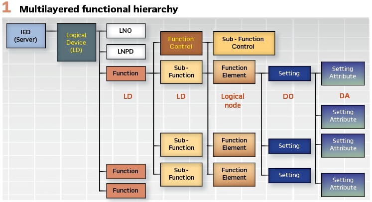
It is good practice to represent the functions in the model by Logical Devices contained in the server (Figure 1).
A function contains function elements – modeled as logical nodes, the building blocks of the IEC 61850 model. A Logical Node is defined as “the smallest part of a function that exchanges data.” It is an object that is defined by its data and methods.
A Logical Device has a single Logical Node Zero (LLN0) representing the characteristics of the logical device itself, may have a single Logical Node Physical Device (LPHD), plus one or more other logical nodes.
Multiple instances of different logical nodes become components of different protection, control, monitoring and other functions in an electric power system automation system. They are used to represents individual steps in a function – for example a different undervoltage level for the trip operation during a voltage disturbance. Logical Nodes contain Data objects and they contain data attributes.
Data Attributes can be simple or nested. The DataAttributes are of certain data type that is of a BasicType for a simple data attribute or composite (DAType) for a nested attribute.
The different Data Attributes can be grouped based on their specific use. For example, some indicate the status of the logical node, while others are used for configuration or measurements. The property of Data Attribute that shows its use is a Functional Constraint (FC). The standard defines many different functional constraints. Some more commonly used are ST (status), SP (set point), and MX (measurements).
The MX functional constraint is used to indicate that the data attribute represents measure and information. The value of this data object can be read, substituted, logged or reported. The values of these Data Attributes are normally based on processed data from the IED.
One of the main interoperability challenges with IEC 61850 based systems is that a large number of data objects and attributes defined in the IEC 61850 standard are optional. That is why we need to define profiles, such as the one proposed to meet the requirements of IEEE 1547. That profile will identify:
- A subset of logical nodes that are required to model the functionality of a DER Controller IED
- A set of optional data objects in specific logical nodes as mandatory in order to implement the functionality
- The grouping of logical nodes in logical devices
Structuring the Device Model with Hierarchical Logical Devices: The functionality of a complex multifunctional IED such as a DER controller is multilevel and is chal-lenging to model using the simple function hierarchy from Edition 1 of the standard. A simple example is the voltage disturbance function. It contains two sub-functions:
- Undervoltage
- Overvoltage
To meet the requirements of such multilayered functional hierarchy, Ed. 2 of IEC 61850 introduced the nesting of logical devices.
The bottom layer of sub-functions contains function elements. As we already mentioned, they are represented by Logical Nodes.
Modeling the Process Interface: The process interface is represented by the logical nodes from LN groups such as:
- Instrument transformers and sensors group T – for example TVTR (voltage transformer)
- Switchgear group X – for example XCBR (circuit breaker)
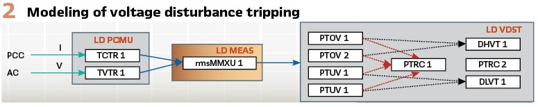
If the process interface with the voltage and current sensors is in a different device than functions performing calculations based on measured values like the MMXU that calculates the instantaneous values, sampled values (SV) are used to transmit the waveform from the sensor interface to the MMXU. The MMXU can make the calculated values available to protection (like PTUV) or DER related (like DLVT) functions.
An example of the use of this modeling principle for voltage tripping is shown in Figure 2.
TCTR1 and TVTR1 digitize the current and voltage signals and provide sampled values to rmsMMXU1. The calculated rms values of the phase voltages are then used by the PTOV and PTUV to determine if there is an overvoltage condition that requires a trip and forward this to PTRC1 to execute the tripping. This information is also provided to DHVT1 and DLVT1.
DER Modeling in IEC 61850
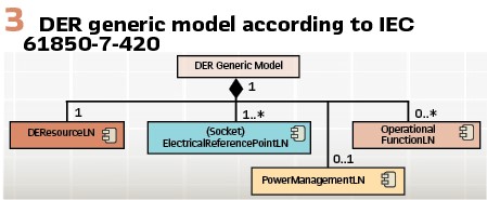
The generic model of a DER according to IEC 61850 consists of the following elements shown in Figure 3. In addition to that generic model, there may be technology specific information available e.g. details of a PV array.
Electrical Reference Point Modeling Considerations: According to IEEE P1547 the reference point of applicability (RPA) is the location where the interconnection and interoperability performance requirements specified in the standard shall be met. The electrical quantities referred to in the standard are those at the RPA, unless stated otherwise. In the IEC 61850 model, the RPA is the Electric Reference Point (ERP)
All interfaces may be hardwired to the terminals of the DER controller or can be digitized using Merging Units (MU). The analog to digital conversion of the current and voltage transformers is performed by the analog interface of the IED.
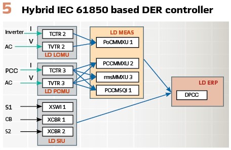
The modeling principle for the electric reference point is shown in Figure 5.
TCTR and TVTR digitize the current and voltage signals and provide sampled values to MMXU logical nodes.
PoCMMXU1 calculates the instantaneous measurements of the electrical parameters at the output of the PV system inverter.
PCCMMXU2 calculates the instantaneous measurements of the electrical parameters at the PCC.
The voltages magnitude and phase angles from MMXU1 and MMXU2 can be used in the DPCC logical node to determine the status of the PCC represented by the data object EcpIsldSt.
The calculated rms values of the logical node rmsMMXU3 are required to meet the monitoring requirements defined in IEEE P1547. The maximum magnitude of phase voltage MaxPhVPhs and the minimum magnitude of phase voltage MinPhVPhs measurements are necessary to monitor the EPS conditions at the PCC and are used as an input to the voltage tripping and ride-through function.
The calculated sequence components values from the logical node PCCMSQI1 can be used to monitor and detect short circuit faults or open phase conditions in the EPS as required by IEEE P1547. Logical nodes XSWI and XCBR provide to DPCC status information for the disconnecting switches and the circuit breaker that can be used for determining the PCC status.
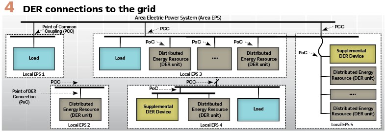
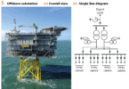
DER Controller Interface Requirements: The DER Controllers play a critical role in the integration of different types of DERs in the electric power system (EPS). DERs can be connected in many different ways to the EPS, as shown in principle in Figure 4 (Figure 2 from IEEE P1547).
The DER Controller needs to be able to support the electric power grid energy management system based on different modes of operation and configuration settings under varying EPS conditions and power output from the renewable resource.
Depending on the type of DER and its location the interface requirements may change. This is especially valid for IEC 61850 based systems in which the replacement of hard-wired connections between the process and the DER controller can be replaced with high-speed peer-to-peer communications.
In order to determine if the inverter is responding correctly to the commands from the DER Controller to the inverter and providing required active and reactive power and voltage phase angle, the controller needs to measure the currents and voltages at the PoC. That is why it needs to be connected to the current and voltage transformers on the output of the inverter. To be able to respond to different events in the electric power system, the DER controller also needs to measure the currents and voltages at the PCC to the EPS. This means that it needs to be connected to the current and voltage transformers at the PCC.
To monitor the status of the switching devices at the PCC, the DER controller needs to be connected to the auxiliary contacts of:
- The circuit breaker CB
- The disconnecting switches S1 and S2
Based on this status information the controller will know if it is possible or not to connect to the EPS.
In case of a fault on the line where the PCC is, the protection IED at the substation will send a Direct Transfer Trip (DTT) signal to the DER controller. This means that the controller should have:
- an interface to the substation protection IED that will allow it to receive the DTT signal
- an interface to the circuit breaker trip coil to be able to disconnect from the EPS
The DER Controller also should be able to connect the DER or reconnect it after it has been disconnected. This will require an interface with the close circuit of the circuit breaker.
Some functions that the DER Controller performs require the monitoring of the voltage angles on the EPS and DER side. Disturbance and event reporting also require time synchronization. That is why the controller needs to have a time synchronization interface.
The DER interfaces and its functionality, as defined in IEEE P1547, will determine the model for the IEC 61850 profile.
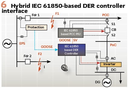
Considering the trend towards the digitalization of the electric power grid based on IEC 61850 and the maturity of the process interface solutions using IEC 61850 GOOSE and sampled values messages, the IEC 61850 based Controller should be capable of having the PCC interfaces using peer-to-peer and client-server communications. Figure 6 illustrates an implementation of an IEC 61850 based DER Controller with a hybrid process interface to the PCC and PoC:
- Hardwired analog interface to the DC output from the PV
- Hardwired analog interface to the AC output from the inverter
- IEC 61850 sampled values analog interface to the PCC
- IEC 61850 GOOSE interface to the PCC switchgear
The IEC 61850 based PCC Process Interface Unit (PIU) is located at the PCC and combines the functionality of two types of interfaces – analog and binary. It is hardwired to:
- The secondary of the instrument transformers
- The auxiliary contacts of the circuit breaker and disconnecting switches
- The trip and close circuits of the circuit breaker
- The open and close circuits of the disconnecting switches
The interfaces between the PCC PIU and the DER Controller is over a fiber optic or wireless communication link using IEC 61850 GOOSE and SV messages. This implementation of communications-based interface between the PIU and the DER Controller offers significant benefits:
- Practically eliminates CT saturation and the safety concerns from high voltage in case of open current transformer circuit
- Significantly reduces construction and installation costs
- Significantly reduces maintenance costs
- Supports condition monitoring of the interfaces between the IED Controller and the circuit breaker and switches at the PCC
A Profile to Support IEEE 1547
A profile to support IEEE 1547 will result in a device model that describes a DER with all the logical nodes to model the functions required to be compliant to IEEE 1547. The LNs need to contain at least the data objects that correspond to the information exchange requirements specified by IEEE 1547.
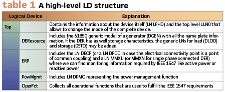
Besides supporting all the requirements from IEEE 1547, such a profile shall also comply to the generic DER model shown in Figure 3. To structure the model, it is recommended to use a hierarchy of logical devices (LD) as supported since Ed 2.1 of IEC 61850. As a high-level structure, we can use the following LD structure (Table 1).
Additionally, the device model would include information related to the switchgear the DER controller is connected to and where e.g., trips from the operational function would be received in case a physical disconnection is required. If no physical disconnection is required, the power management function (LN DPMC) would implement a “cease to energize.”
The power management function responds to the different requests from the various operational functions and calculates the resulting requests for active and reactive power to the DER.
The power management function is modeled with a logical node DPMC. The requested active and reactive power that has been calculated by the power management function is available in the two data objects (DO) ReqTotW and ReqTotVAr. The LN as well includes two DOs that are references to the LN for the DER resource and the LN for the electrical reference point. Additionally, the LN DPMC has multiple setpoints for the requests from the operational functions.
There are setpoints for active power (WSpt), reactive power (VArSpt) and for the power factor (PFSpt). CeaEngzCtl is used for cease to energize request from a power management function.
The FctRef is a reference to the corresponding operational function that is controlling the setpoint. They refer to the corresponding logical device and logical node that is implementing that function. Those are explained in the next chapter.
Modeling the Operational Functions Required by IEEE 1547: The operational functions defined in IEEE 1547 are grouped as:
- Voltage disturbance
- Frequency disturbance
- Return to service after trip
- Voltage and reactive power control
- Voltage and active power control
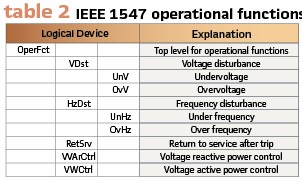
Using again the concept of hierarchical logical devices, the operational functions required by IEEE 1547 can be modeled in the following structure of hierarchical logical devices (Table 2). A logical node DWMX is used to model the capability required by IEEE to limit active power.
Return to service after trip is modeled with a LN DCTE. This LN contains DOs for the settings required by IEEE 1547 like the values for the minimum and maximum for voltage and frequency range and the delays to enter service.
Voltage and reactive power control consist of four elements:
- Constant power factor mode – modeled with the LN DFPF
- Voltage-reactive power mode – modeled with the LN DVVR
- Active power-reactive power mode – modeled with the LN DWVR
- Constant reactive power mode – modeled with the LN DVAR
Voltage and active power control in IEEE 1547 requires a voltage active power mode, which is modeled with the LN DVWC.
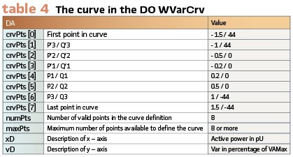
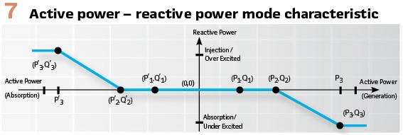
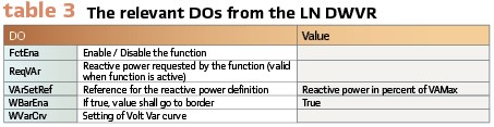
Voltage-reactive power mode, active power – reactive power mode and voltage – active power mode use a curve as a characteristic. The LNs from IEC 61850 support the possibility to describe the curve. To explain the concept, we use the example of Active power – reactive power mode (Figure 7). The relevant DOs from the LN DWVR are shown in table 3, the configuration of the curve in the DO WVarCrv in table 4.
Modeling Voltage and Frequency Disturbance: About voltage disturbance, IEEE 1547 describes:
- Mandatory voltage tripping requirements
- Voltage disturbance ride through requirements
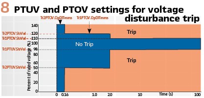
Shall trip and ride through requirements are defined with multiple voltage threshold and for each of them a time. Both are independent, but there is some dependency. Basically, tripping is allowed between the time when the ride through time is over and the trip clearing time expires. The implementation of this functionality can be based on the use of multiple instances of undervoltage (PTUV) and overvoltage (PTOV) elements. For example, if the voltage level during a short circuit fault is lower than the setting Tr2PTUV.StrVal (see Figure 8), it will start the timer of the Tr2PTUV logical node and after the time delay setting Tr2PTUV.OpDlTmms will issue a trip signal.
According to this definition for a DER to meet the IEEE P1547 requirements the overall disconnection time from the fault inception needs to be 160 ms. This time depends on several factors:
- The time for the PTUV or PTOV to start – this for most of today’s devices is about 20 ms
- The time delay setting OpDlTmms
- The breaker tripping time – we can assume about 80 ms for a 5-cycle breaker
Based on such analysis the DER voltage trip function time delay setting will be
Tr2PTUV.OpDlTmms = 60 ms
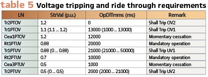
To implement all voltage tripping and ride through requirements from IEEE 1547, the following logical node instances are required (Table 5.) To monitor voltage disturbance events, IEC 61850-7-420 defines two logical nodes DHVT (high voltage ride through) and DLVT. To model requirements from 1547 concerning consecutive voltage disturbances, a new LN DVRT is proposed. Finally, LN PTRC is used to implement the trip based on the operate signals from the over and undervoltage elements that request a trip.
The concept to model frequency disturbance elements is similar, using under frequency and over frequency (LN PTUF / PTOF) elements.
Biographies:

Christoph Brunner is the President of his own independent consulting company it4power LLC based in Switzerland. He has over 25 years of experience with knowledge across several areas within the Utility Industry and of technologies from the Automation Industry. He has worked as a project manager at ABB Switzerland Ltd in the area of Power Technology Products in Zurich / Switzerland where he was responsible for the process close communication architecture of the automation system. He is Convener of WG 10 of the IEC TC57 and is a member of WG 17, 18 and 19 of IEC TC 57. He is member of IEEE-PES and IEEE-SA. He is an IEEE Fellow and is active in several working groups of the IEEE-PSRC and a member of the PSRC main committee and the subcommittee H. He is advisor to the board of the UCA international users’ group.

Dr. Alexander Apostolov received his MS degree in Electrical Engineering, MS in Applied Mathematics and Ph.D. from the Technical University in Sofia, Bulgaria. He is Principal Engineer for OMICRON electronics in Los Angeles, CA. He is an IEEE Fellow and Member of the PSRC and PSCC. He is past Chairman of the Relay Communications Subcommittee, serves on many IEEE PES WGs. He is a member of IEC TC57 WGs 10, 17, 18, 19, Convenor of CIGRE WG B5.69 and member of several other CIGRE B5 WGs. He is a Distinguished Member of CIGRE. He holds 4 patents and has authored and presented more than 500 technical papers. He is an IEEE Distinguished Lecturer and Adjunct Professor at the Department of Electrical Engineering, Cape Peninsula University of Technology, Cape Town, S. Africa. He is Editor-in-Chief of PAC World Magazine.