what incorrect time can lead to and what can we do to receive time reliably
by Galina Antonova, ABB Power Grids, Canada
This article describes what can happen to power system applications if incorrect time is used, why it happens, and how we can fix it. Numerous power system applications rely on synchronization to local or global time such as Coordinated Universal Time (UTC), with varying degree of accuracy. Examples of time accuracy requirements are depicted in Figure 1.
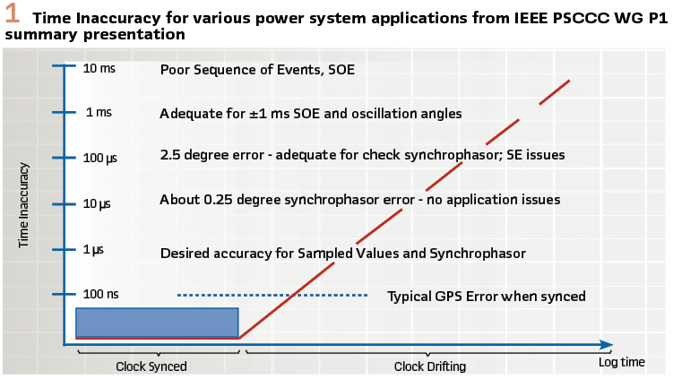
Power systems’ event analysis and reporting requires that disturbance fault recorders (DFRs) and sequence of events (SOE) data be captured with correct date and time information. NERC PRC-002-2 Requirement 10 stipulates “synchronized device clock accuracy within ± 2 milliseconds of UTC.” Many of deployed Remedial Action Schemes (RAS) use synchrophasor measurements with UTC timestamps accurate to microseconds.
Protection schemes, such as line current differential and those using IEC 61850-9-2 sampled values require microseconds accuracy for samples synchronization. To receive time reliably proper design, operation and maintenance of time synchronization are required.
IEEE 2030.101-2018 standard provides detailed guidance on design, installation and monitoring of time synchronization in power utility substations. It covers time sources such as Global Positioning System (GPS) and time distribution technologies, such as Inter-Range Instrumentation Group-B (IRIG-B), Network Time Protocol (NTP), Simple Network Time Protocol (SNTP), and Precision Time Protocol (PTP) profiles for power system applications: IEEE C37.238-2011, IEC/IEEE 61850-9-3:2016 and IEEE C37.238-2017.
A basic time synchronization system from IEEE 2030.101 is shown on Figure 2.
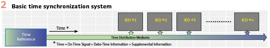
Possible time synchronization sources for intelligent electronic devices (IEDs), such as phasor measurement units (PMUs), DFRs, protective relays and merging units (MUs) are shown on Figure 3.
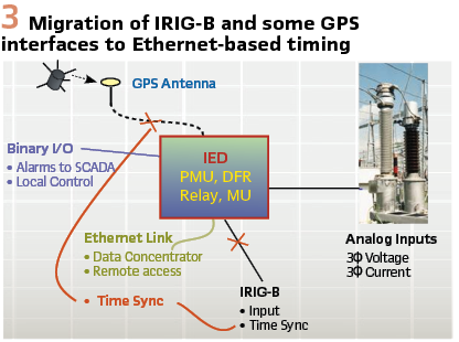
IED’s time synchronization interfaces commonly include GPS and IRIG-B. IRIG-B and some GPS interfaces can be replaced by using Ethernet-based time distribution. This simplifies time synchronization design, eliminates IRIG-B and GPS cabling and antenna, thus reduces cost and maintenance.
What can happen and why time is incorrect?
Fine time synchronization implies that year and date information is correct. Absence of correct year, date and time challenges event analysis and could cause NERC PRC-002-2 compliance issues. Also, enormous time and effort will be spent on sorting time mis-aligned event records within a utility, and even more so across multiple utilities in a region. It was noted that records’ time alignment takes the most time when analyzing events.
IEDs installed today in the field mostly use IRIG-B synchronization. The main reason for not receiving correct year and date information is simply not using IEEE 1344 extensions. While the original IRIG-B format allocated control bits, it did not specify their functions. Transmission of the year, local time offset, leap seconds, daylight-saving and time quality in IRIG-B control bits were later specified by IEEE 1344 and IEEE C37.118 standards.
If IEEE 1344 extensions are not provided or interpreted properly, year and date at the IED will not be correct. It was found while working in the field that it is very easy to think that IEEE 1344 extensions were used when they are not. Often the year at the IEDs can simply be set by the factory to the year of manufacturing, that would be correct initially but will not change at the yearend. A full verification of clocks issuing IEEE 1344 extensions and IEDs receiving and interpreting them correctly is necessary. The simplest way to verify this is to set the year at the IED to future or past and note if it will change to the correct year in a second.
The year information is also needed to get a correct date, as IRIG-B format provides day of the year count (001 to 366). With IEEE 1344 extensions disabled, one could change the year (e.g. to a leap year) and observe a date change.
Time difference in hours could be caused by incorrect interpretation of local time offset transmitted in IEEE 1344 extensions. There was a change in how local time offset is sent and interpreted between IEEE 1344-1995 and IEEE C37.118-2005 standards. Further, IEEE C37.118-2005 standard includes the same specification as IEEE 1344 standard, except it changes the requirement from adding to subtracting the offset to make it consistent with common practice. However, there was a wording inconsistency in the IEEE C37.118-2005 standard that caused confusion; it was clarified in the IEEE C37.118-2011 version. This confusion led to time difference of 2 times the local offset hours in some cases.
Time difference in an hour could occur if daylight-saving information was not interpreted correctly. As the use of daylight-saving time is changing for some states and countries, the most current information needs to be used.
Time difference in seconds can be caused by not interpreting current leap seconds correctly. As the UTC timescale with standardized second duration does not precisely reflect the actual Earth rotation, leap seconds were introduced by the International Earth Rotation and Reference System Service (IERS) to align the UTC timescale with the Earth movement. Leap seconds can occur on the last day of June and the last day of December at midnight UTC. There are currently 37 leap seconds, all of which were additions. Leap second subtraction is also possible and could be more challenging. As it has not yet occurred, it is unknown how existing clocks will handle it.
A single second time difference can occur if the most recent leap second was not properly announced and acted upon.
During an incorrectly processed leap second transition, data timestamps differ from the correct value by one second, and measurements or analog data samples taken at the same time will appear as taken one second apart. This can lead to serious consequences if time synchronized data is used for RAS, automatic controls and other critical system applications, leading to compromised reliability and system stability.
In one example an incorrect leap second transition resulted in halting operation of a utility server and data concentrator after it discarded 5 seconds of received data due to incorrect timestamps.
Another example occurred during line protection end-to-end testing. As a test set at one line terminal failed to register a leap second that occurred a month earlier, fault records were not aligned, and significantly longer time and much more effort were invested into testing than would otherwise be needed.
Time difference in milliseconds could be caused by clock drift or the nature of time distribution protocol(s). NTP and SNTP typically have a ± 1 millisecond time accuracy. This is sufficient for various power system applications, such as those using Generic Object-Oriented Substation Event (GOOSE) messages at the IEC 61850 station bus level. It also meets NERC PRC 002-02 requirement of clock accuracy within ± 2 milliseconds of UTC.
Time difference in microseconds can be attributed to various sources such as clock quality, holdover and drift characteristics, noise coupled into time distribution channel in harsh substation environment, or Global Navigation Satellite System (GNSS) errors. In January 2016 a 13-microsecond GPS error occurred due to a bug in the GPS control system and faulty time predictions were uploaded to GPS satellites.
Time difference in 26 microseconds in 60Hz power systems corresponds to 1% total vector error (TVE), an acceptance criterion defined for synchrophasor measurements. If time is less accurate synchrophasor measurements cannot be trusted, and protection or control schemes relying on them shall be blocked. Phasor data concentrators that aggregate and time align synchrophasor data, also expect timestamps to be accurate to within microseconds, and normally discard the data if this margin is exceeded.
Time difference in 16 microseconds will commonly lead to blocking line current differential protection. For correct Kirchhoff’s current law calculation current samples at line terminals must be synchronized to a common (not necessarily a global) reference. If samples are not synchronized data cannot be valid and protection shall be blocked to avoid mis-operation. Accuracy of time synchronization also determines maximum sensitivity and the minimum pickup setting for the scheme, because any difference less than the one caused by the samples synchronization error cannot be detected.
Examples of utility cases include 500 kV line protection mis-operations caused by a synchronization from a GPS satellite in test mode, and prevention of line mis-operation for unsynchronized line ends, where analysis and finding a remedy took several long months.
Time difference in 4 microseconds to 1 microsecond can lead to blocking all protection functions in an IED, if it relies on digital samples of analog values such as IEC 61850-9-2 sampled values.
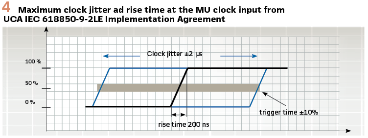
UCA IEC 61850-9-2LE Implementation Agreement specifies an optical 1 pulse per second (1 PPS) signal as a synchronization source. The rising edge of the 1PPS signal sets the sample count to zero. Synchronization to absolute time is not required. Optical cabling is selected due to fiber’s immunity to electromagnetic interference.
The PPS signal rise time imperfection can have an effect on samples timing. An imperfection of 10% is allowed. Network delay is taken into account by limiting jitter to ± 2 microseconds, refer to the image in Figure 4.
Interestingly, a 1 PPS signal can be combined with IRIG-B code transmission if an unmodulated DC shift or Modified Manchester coding are used. With amplitude modulation (AM) signaling separate cables or separate wavelengths can be used to provide both IRIG-B code and 1 PPS in the same fiber optic cable.
Time difference in 100 to 50 nanoseconds can block operation of fault locators or protection operating on the travelling wave principle. Two-way travelling wave methods rely on accurate timing information in their calculations. As the distance to fault is directly proportional to the time difference in the travelling wave arrival at the local and remote terminals, the more accurately local and remote ends are synchronized, the more accurately fault location will be calculated. Only local (not global) synchronization is necessary for these applications.
How to Receive Correct Time Reliability?
The most common method of obtaining global time such as UTC is to use a GNSS, for example GPS, Global Navigational Satellite System (GLONASS), etc.
While much is written about GPS vulnerabilities such as spoofing, GPS has been and continues to be a very reliable system. Instead of looking for what could go wrong, the users can focus on what can be done to receive and maintain good timing from a GNSS. Below recommendations were provided in the paper titled “Protection and Control Dependencies on Time: Applications, Challenges and Solutions.” presented at Georgia Tech Protective Relaying Conference in 2018.
- Choose a reputable manufacturer with a system whose quality matches the needs for accuracy, stability, and security
- Ensure the receiver/antenna/cable system is well-calibrated and has good impedance matching
- Employ best practices for installing the system
- Maintain manufacturer firmware upgrades
- Consult with manufacturer on vulnerability detection and mitigation
- For increased security and reliability, consider installing multiple receivers with diverse antenna locations and a system for monitoring their time differences
- For mitigating loss of GNSS, provide a stable backup timing source (e.g. by using a high-stability atomic oscillator)
As an alternative to GNSS the use of terrestrial time distribution from a national time laboratory has been discussed. It could be possible for a utility to collaborate with a telecom or other provider on obtaining such timing service with microsecond time accuracy range. Also, eLoran, an enhanced version of the Loran-C, long-range, ground-based navigation system could provide a backup or an alternative to GPS in the future. The US Department of Transportation is investigating alternative sources and methods.
For distributing time to the end devices most common method today is electrical IRIG-B. As discussed earlier, to achieve correct year, date, hours and seconds IEEE 1344 extensions need to be properly configured and used. IRIG-B control bits are specified in IEEE 1344, IEEE C37.118-2005 and IEEE C37.118.1-2011 synchrophasor standards. Recently, the use of 17 straight binary seconds (SBS) bits was specified in IEEE C37.237-2018 Standard for Requirements for Time Tags Created by Intelligent Electronic Devices-COMTAG.
To communicate time quality to the end devices IEEE 1344 and IEEE C37.118-2005 standards specified a 4-bit time quality field that, however, is set to zero when clock is locked to UTC, i.e. the actual time accuracy is not known. A new 3-bit continuous time quality field was added in IEEE C37.118-2011 version to continuously communicate the estimated maximum time error.
Thus, the key recommendations for using IRIG-B time distribution reliably are listed below:
- Enable IRIG-B control bits (or IEEE 1344 extensions) for supplemental time information
- Verify that IRIG-B control bits are configured properly for the specific version in use
- Monitor and verify the operation of control bits using an IRIG-B monitor tool, if possible
- Verify that DC shift, AM or modified Manchester coding signaling are configured properly
- Be aware that combining 1PPS and IRIG-B signals is possible, e.g. with DC shift signaling
- Select fiber media over electrical cabling due to fiber’s electromagnetic compatibility
- Utilize optical 1PPS for UCA IEC 61850-9-2LE process bus applications
Some of the IRIG-B challenges were resolved with Ethernet-based time distribution. As PTP distributes time in seconds from the origin of PTP timescale (January 1, 1970), the reception of correct PTP seconds is sufficient to calculate year, date and time correctly. Also, PTP’s mandatory Alternate Time Offset Indication Time Length Value (TLV) extension provides local time, daylight-saving and current UTC leap seconds. Note that PTP timescale is linear and does not have leap seconds like UTC. One challenge found and resolved in early PTP implementations is that local time offset was referenced to UTC not PTP time. This resulted in adding current leap second twice, and the local time being 37 seconds ahead.
The users need to be aware of different PTP profiles currently in existence. Since profile definition in PTP parent standard IEEE 1588-2008, profiles were generated for power, telecom, automation and datacom industries. IEEE 1588-2008 also defines 2 default profiles that are general and do not guarantee any performance. Telecom profiles could be used to distribute time between substations, and power profiles specify synchronization within a substation.
First power profile IEEE C37.238-2011 was split into two standards during revision: base profile IEC/IEEE 61850-9-3:2016 and extended profile IEEE C37.238-2017. While all three profiles follow the same principles: layer 2 multicast messages once a second, and peer-to-peer delay measurements, the revised versions do not interwork with the first power profile.
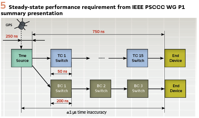
All power profiles guarantee the same performance with ± 1 microsecond time accuracy at the end device. Time distribution network with 15 transparent clocks was specified in the first power profile, and a chain of 3 boundary clocks was added as an alternative in the revised profiles, see Figure 5.
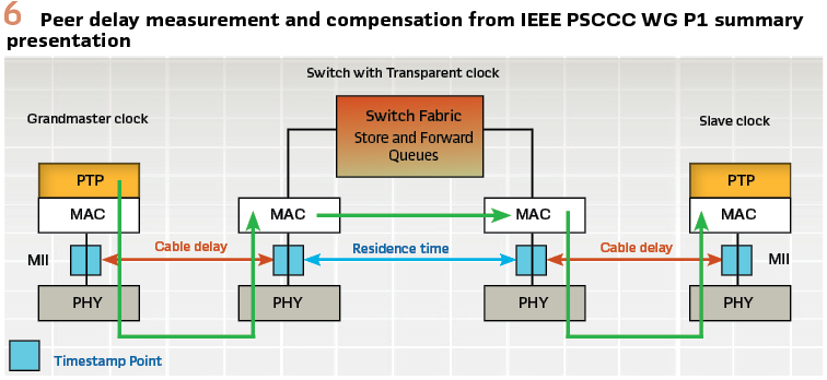
The ± 1 microsecond time accuracy is achievable because three variable delays are measured and corrected for on per message basis: protocol stack delay in grandmaster clock, residence time in transparent clock(s), and delays in communication links, see Figure 7.
The main difference preventing interoperation is that the first profile requires profile specific TLV for best clock selection and profile isolation, while the revised profiles specify standard best master clock algorithm and use domain numbers to separate profiles. Domain number 254 is assigned to extended profile and domain number 93 is recommended for base profile. The first profile also requires IEEE 802.1Q tags, while the revised profiles do not, and leave tags out of scope.
The main distinct feature of the extended profile is continuous provision of dynamic time inaccuracy to IEDs to allow applications to decide on the usability of the received time. For example, line current differential protection shall be blocked, if time error exceeds defined margin.
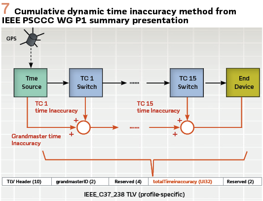
Version 2 profile specific TLV is used to carry time inaccuracy information in a format compatible with version 1 TLV. Time inaccuracy value is initiated by the grandmaster and updated by each device in time distribution network, see Figure 6.
Other features of the extended profile are support for PTP to IRIG-B converters and daylight-saving notifications traversing through up to 7 boundary clocks.
For the complete list of profile differences refer to the IEEE PSCCC WG P1 summary paper “Revision of IEEE Std C37.238, Power Profile for IEEE-1588: Why the Big Changes,” presented at Georgia Tech Protective Relaying Conference in 2018.
Main learnings on using PTP time distribution reliably are captured below:
- Select the same PTP profile version on all devices: clocks, switches, and IEDs
- Choose extended power profile if dynamic monitoring of time inaccuracy is required
- Use basic power profile for IEC 61850-9-2 process bus applications
- Follow IEEE C37.238-2017 guidance on mixed profile operation, if necessary
- Set clock’s priority values per desired grandmaster selection
- Verify and monitor basic Ethernet connectivity between all devices, use fiber whenever possible
- Baseline test and continuously monitor received time accuracy
Conclusions
Time distribution is an invisible service that often gets overlooked. It also often falls into a joint or uncertain responsibility within a utility. Yet, absence of proper time synchronization can lead to significant consequences and enormous time investment. Putting time and effort first into designing and building a reliable time distribution, then operating and maintaining it well will result in improved system reliability and will save us all a lot of our precious time!
Biography:
Galina Antonova is with ABB Power Grids, Grid Automation group, North America. She has over 20 years of experience in the area of electrical engineering, data communications and time synchronization, which she mainly applied to the power industry. In her current role with ABB, Galina is applying her expertise to substation automation and protective relaying applications. Galina received her M. Sc. degree (1993) and a Ph.D. (1997) in Electrical Engineering and Data Communications from the State University of Telecommunications, St. Petersburg, Russia, and spent one year at University of British Columbia (UBC) on a scholarship from the Russian President. She is actively involved with IEEE PSRC and is a Canadian member of the IEC TC57 WG10.