by Burak Tahincioglu, OMICRON electronics GmbH Austria
Having a well-designed secondary project is considered as a key element for a substation. Secondary schematics consist of many subparts including single line diagram (SLD), electrical overview, cable diagram, wiring diagram, terminal plan, connection list and so on. Traditionally, commissioning of protection, automation, and control systems (PAC) during site acceptance testing (SAT) starts with marking all pages of the secondary project to ensure both ends of the cables are terminated at correct locations designated on the project.
These activities are based on visual checks, basic electrical continuity tests and analogue injection applied to the circuits. Finally, observing the displays, LEDs, alarms or simply witnessing the correct functioning of the devices completes the “functional test” part of commissioning activities.
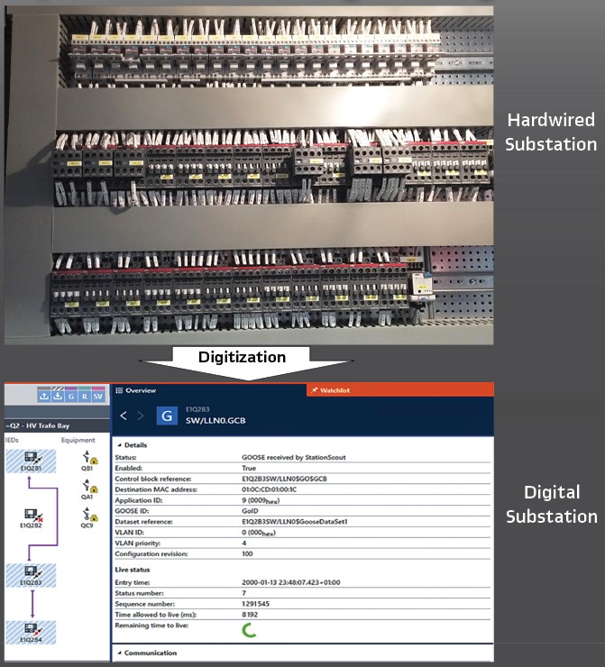
There are many concepts applied to secondary projects to keep the running PAC system representing an exact replica of the secondary project, even after substation is exposed to modifications and extensions. When the transition from paper drawings to IEC 61850 system configuration language (SCL) data started, it is observed that a lot of useful electrical drawing concepts which similarly exists in SCL is often not engineered.
The traditional approach of utilities during tendering stage of a substation is specifying the requirements in written format, and as a result contractor shall deliver electrical projects for approval, matching these specifications. Throughout the years, utilities have been continuously updating their specifications to include more and more information in the electrical projects to gain the optimum benefit. The more information included in the projects, the more efficient commissioning and operation experience is expected. A challenge to tackle during the digital transformation journey would be to develop a new specification and project approval concept for transferring maximum information included in electrical drawings to the machine-readable SCL data. In the following sections of the article, the similarities between electrical drawings and SCL files and some of the important features of electrical drawings that can be implemented to SCL to increase efficiency for commissioning and operation is discussed.
Analogies between electrical drawings and SCL files
Some years ago, electrical drawings started to be drawn using computer aided design (CAD) software instead of hand drawing. Another step forward was witnessed with using intelligent design software which automatically generates wiring and cabling diagrams out of electrical schematics. Both developments had an impact on reducing the human errors and decreased the duration of project preparation significantly.
Even though the improvements described above eased the project design process, while switching from hard wired substations to IEC 61850 based substations, another challenge is introduced. The information included in electrical drawings is required to be transferred to IEC 61850 SCL file. Below some analogies are described to establish a relationship between electrical drawings and SCL file
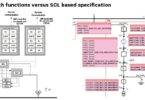
Single Line Diagram – Substation Section: SLD gives an overview about the switchgear characteristics, busbar arrangement and electrical connections of the substation. From protection and control point of view, it is the basis for allocating protection functions and generating interlocking logics. Therefore, it is a common practice to include SLD as one of the first pages in electrical drawings.
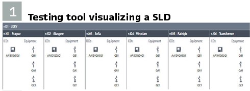
IEC 61850-6 refers to IEC 81346 regarding the reference designations for naming structural substation elements. SCL file follows a similar order like electrical drawings about SLD. It starts with <Substation> section. In substation section, the hierarchical elements can be defined with the tags <Substation>, <VoltageLevel>, <Bay>, <ConductingEquipment>, <SubEquipment>, <Terminal>, <ConnectivityNode>. The exact location of the equipment can be specified according to the coordinates. For this purpose, SCL allows using <sxy: x> and <sxy: y> coordinate tags. How a testing tool visualizes the same SLD without busbar connections (zero-line diagram – ZLD) upon an SCL import is shown in Figure 1.
Given that SLD information is included during SCL engineering, this information can be read out by other tools such as test devices, HMI (Human Machine Interface) or any other clients which utilizes SLD information. For instance, HMI can create SLD automatically out of the SCL file, on the other side SAS test devices can generate test cases automatically out of the SCL file for testing HMI.
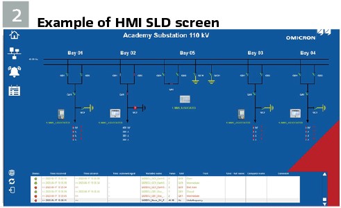
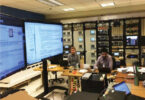
This automated engineering workflow eliminates the intermediate steps that are open to human error such as manual design of the SLD during HMI configuration and creating manual test cases for testing HMI. An example HMI SLD screen is shown in Figure 2. SAS test device automatically creating test steps from SCD to test this HMI SLD screen is shown in Figure 5.
On the other hand, there is still ongoing activities of IEC 61850-6-2 for defining Graphical Configuration Language (GCL) and the HMI Configuration Language (HCL) formats.
Substation Equipment Naming: Assuming SLD information is engineered in the SCD file of the substation, the next analogy to apply should be equipment naming. It is important that utilities develop a standard naming concept for substation equipment.
Non-negligible number of electrical drawings used to refer to DIN 40719-2 to apply a consistent naming concept. Even it has already withdrawn, some of the utilities still stick to the historical norm because of backward compatibility concerns. Currently, the normative reference for substation equipment naming in IEC 61850-6 is IEC 81346 which is the successor of DIN 40719-2 and IEC 61346.
For the utilities which have DIN 40719-2 naming concept applied in electrical drawings for years; transition from hardwired interfaces to IEC 61850 creates discrepancy and unfamiliarity in terms of new equipment naming convention used in SCL referring to IEC 81346.
Some IED configuration tools by default applies IEC 81346 equipment naming, some tools allow freely configurable names. It is still possible to keep DIN norm conformity and use IEC 81346 naming with good engineering practices. SCL allows to define a description attribute with <desc> tag for conducting equipment together with its name. This will keep the utility traditional naming alive in SCL files like in electrical drawings.
Testing tools developed guessing algorithms based on equipment naming to place conducting equipment automatically, even there is no x and y coordinates available in the SCD file. Moreover, the tools can show both the name and description tags of the equipment to give better overview for testing and operation.
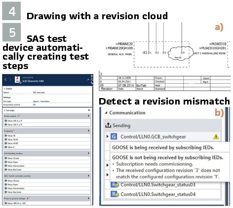
Revisions on the drawing – Configuration Revision Number: It is common that during the years, some extensions or modifications might be required. Revisions on the diagrams are tracked with a revision number on the drawing, generally accompanied with the name of a person who made the change, date and reason of the revision. It is ensured that the running PAC system is represented in an up-to-date project. Modifying the drawings according to the changes requires manual execution.
SCL file contains a similar philosophy for all services: GOOSE, Reports and Sampled Values. According to IEC 61850-6, changes on the GOOSE Control Block datasets increments the ConfRev counter. It is recommended to increment this by 10 000 on each configuration change, to distinguish this from online changes leading to an increment of 1 only. Mismatch of the ConfRev leads to failure on subscription of GOOSE.
The testing tools verify the ConfRev values between SCL file and the values received from network. Continuous monitoring in operation using such tools ensures the reliability of the IEC 61850 services running on.
Figure 4 (a) shows a drawing with a revision cloud and Figure 4 (b) shows how testing tools can detect a revision mismatch, in case an IED configuration for GOOSE is changed but SCL is forgotten to be updated.
Cable number – GOOSE (GoID) Identifier / Report Identifier (Report ID): In hardwire interfaced substations it is common to decide for a cable coding principle representing various specifications of the cable such as voltage level, bay number or duty of the cable. With this principal being applied, it is much easier for the technician to identify cables by looking at written or attached numbers.
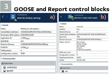
SCL allows to group GOOSE messages according to an application orientation. One of the GOOSE control block attributes for this purpose is GoID (GOOSE Identifier). It can be a good engineering practice to define GOOSE identifiers while keeping the cable number conventions. GOOSE identifier is a text string, if not engineered it will get the GoCBRef (GOOSE Control Block Reference) by default. In most cases, it is assumed that cable numbering format can conform with the GoID data type.
The same convention is also applicable for Report Control Blocks. Figure 3 (a) is a GOOSE Control Block and (b) is a Report Control Block from a SAS test device visualization.
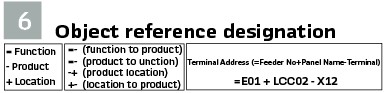
Object Reference Designation – GrRef, ExtRef, IntAddr attributes: Each object (component or functional unit) in a substation is given an “object reference designation” in electrical drawings. The different aspects of an object are shown below in Figure 6, left. This format supports creating a hierarchical structure in the substation to have multiple levels with different aspects. As a result, each object in a substation will have a unique reference designation. Figure 6 in the middle shows transition from one aspect to another and on the right an example object reference of a terminal.
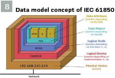
Data model concept of IEC 61850 shown in Figure 8 supports a hierarchical structure. Besides classical data model structure, Logical Devices (LD) in the data model may also have a hierarchy starting with edition 2. This is achieved with Data Object (DO) called GrRef. GrRef consists of a DA (data attribute) of SetSrfRef as an object reference showing the parent or root LD of the LD. GrRef is located in LLN0 of LD. There can be multiple levels of LD hierarchy. It is also important to know that parent LDs inherit some of their attributes to child LDs such as behavior, namespace, statistical calculations.
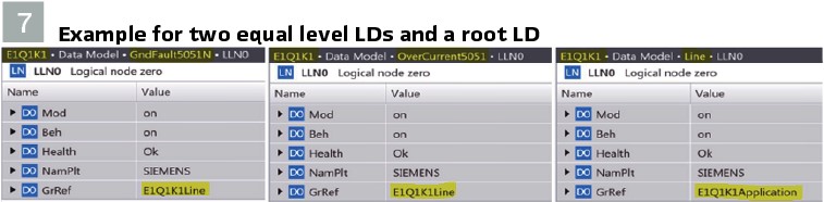
One example is shown above in Figure 7 for two equal level LDs: “GndFault5051N” and “OverCurrent5051” are child of “Line” LD and Line LD is the child of “Application” LD. “Application” LD is the root LD.
The other important electrical drawing feature is called wiring diagram or terminal plan. Each electrical terminal has at least two connections, one is coming down from a cable of another location and the other one is going up to the device in the same location or shorted to another terminal in the same rail. In physical realization, terminals have number or symbol tags, and the wires have shrinkable tubes wrapped around with the incoming/outgoing address printed on. This is widely applied and helpful for detecting connection failures easily.
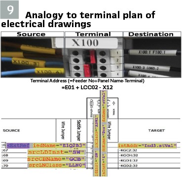
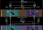
An analogy to terminal plan of electrical drawings can be established for GOOSE message subscription with <ExtRef> tags. A GOOSE message can be thought of as a terminal which has a cable connection from publisher and an internal wiring upwards to the subscriber. In Figure 9, this analogy is shown with related elements of the GOOSE subscription from SCL file. <IntAddr> is filled out by subscriber IED to point out the designated variable for the related dataset element.
A member of published GOOSE dataset which desired to be subscribed is the analogy for “terminal”.
ldInst=”SW” lnClass=”XSWI” lnInst=”3” doName=”Pos” daName=”stVal“
The internal variable that subscribed GOOSE is designated to is the analogy for “target”.
intAddr=”Ind3.stVal“
The published GOOSE Control Block address at publisher IED is the analogy for “source”.
<ExtRef iedName=”E1Q2B3” srcLDInst=”SW” srcCBName=”GCB” srcLNClass=”LLN0” />
Testing
In substations with conventional hardwired interfaces, all wiring and cabling connections between IEDs need to be checked as part of the FAT and SAT. This is performed one-by-one in a manual process of “green marking” all interfaces at printed functional and wiring diagrams (“bit-testing”). For testing the relay logics, the physical inputs need to be forced and logics verified either by monitoring LEDs, outputs or with assistance of the IED software. For testing the HMI signaling, an end-to-end (also referred as point-to-point) check is performed by stimulating the signals directly at the equipment level in the switchyard or by forcing them at the IEDs. Additional documentation is usually needed, like a spreadsheet with RTU signal and mappings list (“data point list”).
In a substation with IEC 61850 communication-based interfaces, the process of testing automation and control can be improved by using software to replace some of the manual steps applied before. This process can be even more efficient if some optional features defined by the standard are used as well as the capabilities of the System Configuration Language (SCL) is fully exploited.
Two major testing activities of SAS: “testing interlocking logics” and “testing SCADA signaling” based on SCL in contrary to testing based on electrical schematics is discussed in the following subsections.
Testing Interlocking Logics: Testing interlockings in conventional substations according to electrical schematics is cumbersome. The negative aspects can be summarized as:
- No concrete test plan
- No documentation as a test report, only a tick-off or a punch list
- Tests are executed according to BCU logics drawn in error prone electrical schematics
- Test steps are a habitual subset of switchgear status combinations, not every combination is tested
- Intermediate and faulty status of switchgear position indications are often skipped
- Negative test cases are not fully covered, also command assessments
- Automation is not possible
Above all, whether it is a hardwired interlocking or not; testing interlockings with electrical schematics is a visual inspection activity. A positive release signal is checked with a command issued by an IED. Given that this command is resulting with position change of the switchgear, it is assessed as passed.
Respectively, a negative release signal shall result with no position change to be assessed as a “passed” test result. Here, often there is no additional coverage of cause analysis for the rejection of the command.
On the other hand, IEC 61850 SCL file-based testing offers much more possibilities and efficiency in both test execution and test result documentation. Logics can automatically be tested by simulating the inputs of the logic (either via IED simulation or real switchgear status) and the result of the logic can be assessed.
To represent the result of interlocking logic conditions, IEC 61850 represents the status of the release in the logical node CILO. For testing, all combination of inputs can be tested, and the logic output assessed by reading the CILO status values automatically. This approach does not demand definitions of the logic conditions within the test set since the result is checked in the CILO logical node.
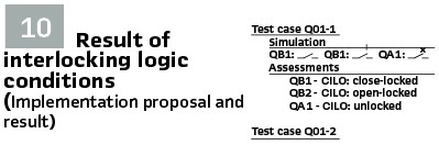
Figure 10 shows implementation proposal and result. Such signals can be controlled, can be used for signal assessment and the command can be assessed.
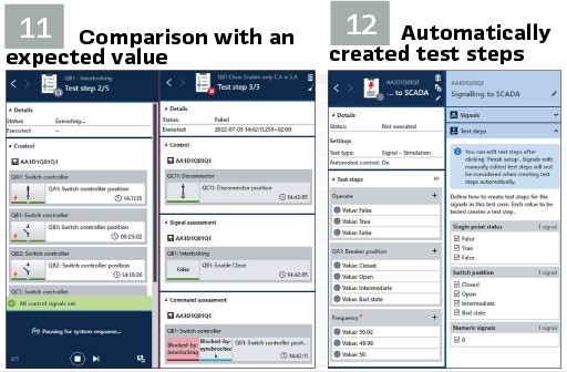
Assessment means the comparison with an expected value. Figure 11 shows an example. Assessments can be done manually or automatically. In addition to the automated assessment of signal values like CILO logical nodes, the test system can issue command operations and check the command response from a switch or bay control unit. Using enough of a timeout value this can also be done by assessing results from hard-wired interlocking logic. The system will automatically issue the correct switching command based on the current position of the switch. The assessment depends on the selected result. If a command response according to IEC 61850-7-2 is selected (for example Blocked-by-interlocking), the system checks if the actual response matches the expected response and assesses the test step as “Passed” or “Failed.”
Testing SCADA Signaling: The schematic drawings-based way of testing signals transmitted from IEDs to SCADA is another time-consuming testing activity. Here, the workflow includes:
- Creating a hand-made spreadsheet signal list of transmitted signals
- Defining a reaction matrix of signals with different indications in this signal list
- Definition of multiple destinations (event list, alarm list, SLD etc.) in the signal list which signals are expected to appear
- Stimulating signals from the process to check reactions defined in the signal list, so-called end-to-end tests
- Tick-off a list for each different destination and observing the behavior as assessment
Contrary to this long-lasting manual process, testing with SCL file allows to create a closed-loop end-to-end testing of signals transmitted to SCADA; from process to control center. Some tools like OMICRON StationScout allows to perform the assessment without an additional documentation. It is important that test cases could be repeatable in order to support different phases of SAS lifecycle such as FAT, SAT and tests during operation and after a firmware upgrade.
Automatically created test steps: Signals, available in the signal list mentioned, must be tested. The signal can differ (double point indication vs. single point) and demand different steps during the test. This results into different test steps (Figure 12).
Although, there is not a specific rule for on which statuses or analogue values to be added as a test step, it is customizable to select the desired values out of the offered test steps.
One example would be based on the current and voltage transformer ratios defined in ARtg and VRtg data objects in TCTR and TVTR logical nodes of the SCL file, predefined test steps can be offered for different phases. With this method, one of the most common mistakes, applying incorrect measurement transformer ratios for measurement values verification can be avoided.
Extension for fully digital substations and additional protocols: The approach presented can be extended with older communication protocols as IEC 60870-5-104 and DNP 3. They are widely used for the communication to control centers. Even if the protocol information as well as the texts to be used are available in the Excel datapoint list, the missing representation in the SCL-files remains a challenge. Fully digital substations with Sampled Values can be covered with this approach easily.
Biography:

Burak Tahincioglu received his bachelor’s degree in Electrical & Electronics Engineering at Mersin University (Turkey) in 2009. He worked as a protection and control engineer at national transmission system operator of Turkey (TEIAS) from 2011 until 2019. He was part of the team commissioning the very first IEC 61850 based substations in Turkey.
In 2019 he joined OMICRON as application engineer for substation automation system testing solutions. He also works on SCL Engineering topics for supporting utilities in this area.