by Diego Gasca and Burak Tahinsioglu, OMICRON electronics, GmbH, Austria
Why build a digital substation? There are several reasons why utilities are building digital substations, in many cases the trigger is to use the first digital substation as a playground for motivated technicians. It follows learning about the process bus technology with Sampled Value (SV) messages and the communication network. Hence, a comparison test against GOOSE versus hard-wired trip is often considered. Some other digital substation projects are sourced from real technical requirements such as space limitations, or some circumstances where conventional wiring or instrument transformer are not feasible (common cases with mixed cable-OHL).
There are also other types of motivations, applied by utilities who are looking at the skyline and realize that upcoming challenges in the horizon like integration of DERs, Smart Grids, data analytics, Virtualization, cost saving over time… are only achievable with a digitalized platform base.
It does not matter what triggered a digital substation project, the testing is, and will be, the key component to guarantee a reliable operation. After been involved in different digital substations around the world, we would like to summarize some aspects that can improve your experience in this new environment and avoid falling into common mistakes.
Improved Specifications
Traditionally, the focus for testing started at the Factory Acceptance Test (FAT) and is complemented during the Commissioning, onsite. We have found several projects facing problems at an advanced stage. The workarounds are not viable, because of extra delays and tight time schedule, or simply due to unsupported capabilities of existing devices. There is a well-known quote applicable during project specifications “if you don’t ask for it, you don’t get it.” That is exactly one of the main traps where digital substations projects fall into. Because of a lack in IEC 61850 specifications, the final product might be highly contractor-oriented, or simply not fulfilling the key utility expectations: “reusable, maintainable, interoperable.”
The technical specifications of a digital substation should include detailed requirements about functionalities expressed in terms of Logical Nodes and Data Model. Besides, communication and time synchronization capabilities (performance, seamless redundancy, segregation and PTP alternatives), as well as monitoring and testing capabilities in form of testing ports, bandwidth, IEC 61850 options (GOOSE and SV supervision, Simulation and Test modes), to mention a few. Consider the case of testing a busbar protection function, where all IEDs and the network were correctly configured and tested off-site, using the traditional style secondary injection, but when testing on-site was needed, the user realizes that doubling the traffic of SV was not considered, or testing ports were not estimated, or even some of the IEDs receiving the trip-GOOSE with Test flag don’t support this functionality yet. These are some examples which a proper technical specification including detailed IEC 61850 capabilities are indeed needed. Basically, the sentence of: “…substation shall be based on IEC 61850” in the specifications is not enough at all.
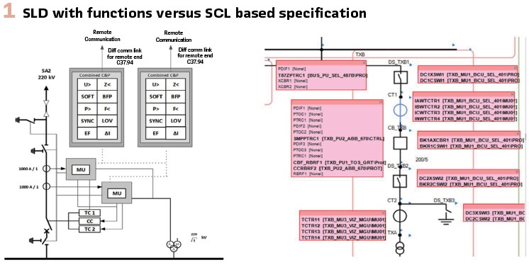
A new trend in specifications is gaining adepts. IEC 61850 opens the door for a unified language where users can customize the data to be used in their system. As a tailored and harmonized basic application profile, completely vendor-agnostic and project independent is becoming the reference for any new project. This is exactly what some utilities are implementing by following a Top-Down approach, where specifications include the required IED capabilities by providing a subset of specified IEDs (in form of SCL files), as well as the expected typical horizontal and vertical communication. This kind of templated-based project also brings additional possibilities by defining utility-standardized test plans based on generic configurations, improving the testing quality, reusability, and efficiency right from the beginning in office environment. In this approach, it is even possible to define allocations of the functions and distributing them amongst the virtual IEDs. This is the same principle of digitizing the traditional single line diagram with IEDs attached ANSI codes. (Figure1).
Testing During the Design
In this stage, the system specification is developed in SCL format as a list of protection and control functionalities required by the utility, represented in IEC 61850 language as Logical Nodes in a pre-defined Data Model structure and the Communication Service Model. In that regard, the initial test should be verifying if the specific IED model and firmware meets the requirements defined during the specification.
Using System Specification Tools, it is possible to compare the SCL from the specification phase against specific vendor ICD files, and get a detailed list of discrepancies, the goal is to validate that all required Logical Nodes, Services and capabilities are available in the actual IED used.
In the early stage of engineering, when multicast messages and reports begin to appear in the SCD file, it is a good time to start verifying the communication relationships. Of course, in the beginning, the information contained will be sparse and need to be improved over time. But inspecting the SCD files early brings advantages:
- The system integrator is pushed to start early with the IEC 61850 engineering to be able to deliver the SCD files
- The awareness of the customer encourages the system integrator to deliver good engineering data
- The progress of the IEC 61850 engineering is continuously checked. Inspecting the SCD file is the only way to do so
- Errors in the engineering can be detected early and the fixes can be applied when this is still easy to do
- The SCD file can be already used to simulate the SAS according to the state of the engineering
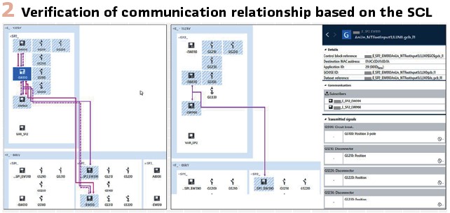
With proper tools it is possible to visualize the signal mappings in a logic-shaped way, analyze the SCD and identify anomalies in a comprehensive environment. Figure 2 shows the communication overview with a tool where the mapping of IEC 61850 messages is tracked down to the specific subscribers.
Testing at FAT
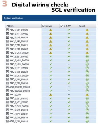
Traditionally, the first thing to do before starting tests is so-called: “Wiring Check.” To verify secondary circuits are exactly the same with the schematics, plays an important role. In digital substations, nothing changes in this regard, but the method only. Marking-up the circuits in schematics has changed to verifying the information on the network against SCL file. And the marker pens are switched to SCL testing tools for accomplishing this highly important task. (Figure 3). This verification is often done first in FAT, then has to be repeated on SAT to reach as-built state. Eventually SCL file must be maintained throughout the lifecycle of the digital substation against any changes. Our experience is, a new job role in utilities called “SCL Manager” is on the horizon who has the task to keep SCL file always up to date.
One of the greatest benefits of testing in a digital substation is the possibility of simulating missing devices and switching from one test scenario to another without changing wires. It expands the possibilities and makes the testing faster and with higher quality.
A common mistake made during FATs, is to address the testing without considering the IEC 61850 Simulation and Test modes. Many users prefer to test with secondary injection, as FAT happens in an isolated environment. Thus, they ignore the possibilities and do not practice how to use it in the safe environment of FAT and pretend to take advantage of it in later stages. In the real substation network, unfortunately there is no room for hesitations.
We recommend getting familiar with these concepts during FAT and check under different test scenarios with identical maintenance tasks. There might be unexpected issues when combining new firmware version with old ones, because these capabilities are still new for some IED series.
Testing the automation system in a digital substation brings many new possibilities and flexibility. Thanks to SCL files and innovative testing tools, it is possible to create automated test plans as a combination of real devices under test (DUT), simulated surrounding devices and even hard-wired process simulators.
In the past, this task was mainly a manual verification process, with no option of re-usability, and the time spent for completing the full Substation and Automation System (SAS) testing was one of the largest components of the full system test.
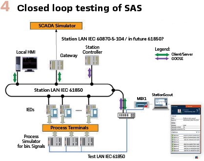
During the testing in a digital substation, the individual components: BCU, SCU, Gateway were addressed separately, based on the SCL file; and as expected from real projects, the permanent changes of SCD versions as part of the engineering process, forced to update the test plans repeatedly. This is why it is recommended using testing tools supporting the SCD update. Being able to control all system inputs (physical and GOOSE signals) together with automatic assessment of the logic outputs, and controlled execution of commands, it is possible to perform an automated closed loop test for the individual component in the SAS, just by powering up the IEDs under test and without need of the full switchgear or a crafted process simulator (Figure 4).
Later during Site Acceptance Test (SAT) when all components are available and interconnected, it is possible to update the test cases and execute the full-chain system test by operating the real primary devices. The main outcome of performing a detailed FAT with re-usable test plan is the time reduction for on-site testing.
First recommendations for SAS testing are to think long term when defining the test strategy, re-usability should be a high priority followed by exhaustive test cases, including positive and negative conditions. It might require an extra effort at the beginning but will pay off when repeating the test cases for typical bays or during the different project phases (FAT, SAT, Firmware updates, Maintenance). Second is to include the signals needed for the testing as part of the Data Model, in some projects we found a lot of signals hidden as part of the Data Model reduction, consequently blocking the options for testing.
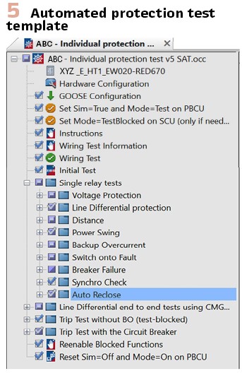
The changes for testing protections in a digital substation are not a big concern for protection specialists, test plans can be easily adapted just by replacing the traditional Pickup and Trip signals by GOOSE messages, and the hard-wired current and voltage signals by Sampled Values (SV). Nevertheless, it is not actually bringing any new advantages beyond the reduction in wiring manipulation. In the projects we have participated in, we created enhanced test plans combining the automatic control of IEC 61850 Simulation and Test mode as part of the test plan routine. This combination enables to create automatic test sequences, not only evaluating the protection functions itself, but also guiding the user throughout the experience of using the full testing capabilities that IEC 61850 brings, in a secure and step by step process. It is also a mechanism to double check that all IEDs are restored to their original operation mode just before the test is finished, similar to not forgetting to remove the test plug in conventional substations (Figure 5).
In this direction, some utilities are also specifying the list of protection signals required for testing, during the IEDs specifications (Top-Down approach), by defining a standard vendor-agnostic GOOSE message and Dataset, to be used only for testing purposes. With this approach, the same GOOSE mapping can be quickly re-used from different vendors, just by copying the GOOSE configuration from one test fil to other one.
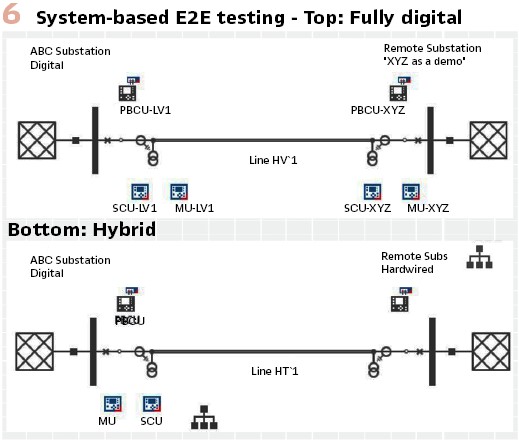
When speaking about system-based testing, either it is a Busbar protection function, a three-winding transformer or an End-to-End line protection, the advantages of testing in a digital environment are much more evident, due the reduction in complexity by bringing all signal together in the same test environment. Also, after completing all the necessary IEC 61850 configuration, testing is basically as simple as testing with hard-wired signals but without dealing with all connections and changes necessary to replicate different topologies. As mentioned earlier, the simulation capabilities also bring possibilities for testing at FATs when not all components are available, as described in the following.
An interesting example to share, was related to testing an End-to-End Line protection function when the local end is fully digital with SV, and the remote end is conventional with hard-wired signals but not available during FAT. To complete this test, a second full-digital bay was used instead, and a fully digital End-to-End test case was performed. Later, during SAT, a minor test plan adaptation removes the Merging Unit and SCU in the remote end, and repeats the same test cases, but this time considering the real tele-protection channels, and the real remote IED (Figure 6).
Another important milestone during protection testing is the busbar protection system. Testing it requires all the signals involved in the zone selection logic, including positions from disconnectors and breakers associated to the busbar, as well as the currents for each test case. Protection specialists normally use crafted process simulators to manually control the system under test, and they need to split the busbar in small segments due to the limitations with analog channels in the test set. It explains why it is one of the more time consuming and laborious test sequences. The first concept to be changed in a digital busbar protection is that zero current does not mean no SV, instead, the SV stream should be transmitted but with magnitudes of zero. It means that all SV streams need to be simulated simultaneously to prevent the protection gets blocked (similarly for GOOSE signals). Testing it with this technique extends the capabilities of a test set to publish multiple SV streams and use multiple test sets simultaneously to complete the test requirements. With the full mapping of currents and positions, the protection people can focus on the protection test cases and zone selectivity, hiding the IEC 61850 concepts in the background. With good preparation, we could complete a busbar protection test including breaker failure function in less than half-day, including more than eighty test points with multiple topologies, and as expected, without doing any wiring changes.
It is recommend to check the GOOSE and SV subscriptions in the central busbar protection unit, before starting with the test cases, signals simulated by test set shall be identical as configured in the distributed units (SCU) and MUs, this process is quite similar to a conventional wiring check, but with GOOSE and SV messages instead.
Testing the communication network has never been more important than now. It is the foundation for all protection and automation functions in a digital substation and cannot be underestimated. The test should include the redundancy via the seamless architecture, propagation delays for real time messages, as well as the bandwidth and segmentation for process or station bus network traffic, whether it is physical or virtual network separation.
Bound to the communication network configuration and testing, is the PTP synchronization, what we have identified as one of the more often underestimated topics in digital substation projects.
It is especially recommended to check the protection function behavior under critical PTP conditions, like poor satellite reception on cloudy days or antenna failures, and during holdover.
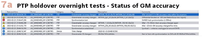
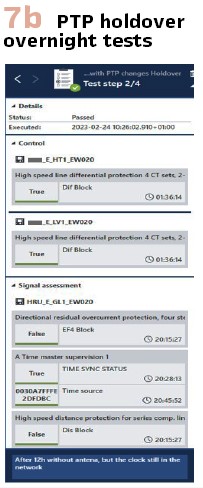
How the IEDs, and especially MUs process the changes in the Clock_class and how they update the smpSynch as a key input for subscribers to validate the usability of those streams. It is becoming increasingly popular in network architectures to include two clocks and even both connected redundant in the PRP network. For those scenarios, it is particularly important to test the protection system response when MUs are synchronized to different Clocks, in parallel to satellite reception issues or antenna failures. (see Figures 7a/7b).
Interoperability for GOOSE and SV communication is a fact, it has been tested many times. Nevertheless, from time to time, there are some interesting cases where detailed analysis is needed to realize the root cause of problems.
A good example is the propagation delay of SV streams is checked by some vendors in order to subscribe or refuse to a specific stream. In the past, subscribers only looked at the smpSynch flag as proof of Global, Local or no synchronization status from MUs, but nowadays some IEDs are smart enough to check the SV time reference (SmpCnt) against their own time and calculate the delay, and even when both publisher and subscriber are correctly synchronized there might a problem due incorrect delay settings.
This kind of troubleshooting is the most challenging task we have faced, that only can be solved with the aid of very accurate network analysis tools in combination with a good understanding of the system.
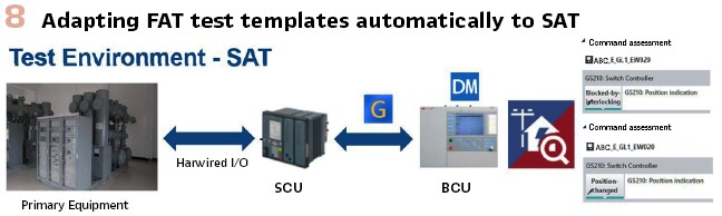
Adapting the Tests to SAT
Most of the test cases already mentioned during FAT need to be repeated during SAT, especially because at this stage all devices are available, then we can take advantage of that and test the Protection, Automation and Control system as a complete solution, including the remote communication with the control center and the operation of the primary devices.
As mentioned, we can take advantage of test plans created during FAT and turn those devices previously as simulated to real devices to be interrogated instead and complete the picture of our test by involving all elements together.
We will not say that injecting secondary signals and verify the complete impedance zones is necessary during SAT, but at least some real trips and auto-reclose should be completed to verify the full protection chain, also measuring the final propagation time under the real communication network conditions. As a recommendation, only if the complete busbar is available for testing, perform a Busbar failure trip using the IEC 61850 Simulation and Test mode, and verify that you can test, even the busbar protection, without interfering with any feeder. It will definitely increase the confidence of using the new testing capabilities and let you demonstrate to all participants the advantages of becoming digital.
Of course, to close with a gold medal, perform a real trip, and validate that all your breakers operate correctly. (Figure 8).
From time to time, we have been requested to inject primary signals and validate the accuracy, phase sequence and phase angle deviation of NCIT, especially working with GIS. Then it is time to inject primary values and verify SV. For doing that, we recommend using a proper filtering of Ethernet traffic to ensure a smooth reading of SV and focus on only analysis of the SV stream under test.
Off-site Setup
Testing in a full digital substation is a matter of combined skills and tools. It is necessary that more and more control and protection specialists should look at the communication field. All previous knowledge of conventional substations is applicable. But now instead of thousands of wires drawn on schematic diagrams, fiber optics and machine-readable documentation can illustrate and analyze the traffic, providing a better understanding and performing auto-diagnostics.
To get familiar with these new skills, tools, and settings, it is recommended to establish your own off-site setup, in the commodity of your lab. After that get familiar with the concepts, try the testing capabilities yourself, run the test sequences and compare it against vendors and firmware versions. Some utilities are using this lab as a pre-qualification area where they can validate if IEDs meet their specifications. They also use it as a training area for new team-members or in general as a technical playground.
Operation and Maintenance
How to maintain a new digital substation is one of the main concerns for utilities. Updating the traditional guidelines, test plans, and modifying the training program will be required in order to achieve the goal of not only building the first digital substation, but instead defining the road map for future projects.
The recommendation for a successful transition is collecting the people related to the substations around the same table. From asset management, IT, project managers, innovation teams, to the operation and maintenance teams. It is necessary to provide the proper training according to their needs, include them during the different project phases and facilitate a test environment as described before.
The success of building a digital substation should not be measured with saving money by replacing copper cables with fiber optics. It is mainly about people, reaching an agreement between well-established control and protection philosophies as well as being open to adopt new technologies.
It is expected to face some resistance, but with proper management support, training, and teamwork it will become the new substation standard.
Biographies:

Diego Gasca studied Electronics and Telecommunication Engineering. He received the MSc in Engineering Project Management and has more than 15 years of work experiences in that field. Diego started at OMICRON in 2016 as regional application specialist for protection and automation in Latin America. At the moment he works as Application Services Expert in customer projects at OMICRON Austria with the focus on power utility communication and protection in digital substations.

Burak Tahinsioglu received his bachelor’s degree in electrical & Electronics Engineering at Mersin University (Turkey) in 2009. He worked as a protection and control engineer at national transmission system operator of Turkey (TEIAS) from 2011 until 2019. He was part of the team commissioning the very first IEC 61850 based substations in Turkey.
In 2019 he joined OMICRON as application engineer for substation automation system testing solutions. He also works on SCL Engineering topics for supporting utilities in this area.