Comparison of Processes for Testing, Commissioning and Maintenance Methods
Craig Wester, Mike Ramlachan, GE Vernova, and Eugenio Carvalheira, OMICRON electronics, USA
This article introduces protection engineers to the differences and similarities for testing, commissioning, and maintaining digital versus conventional substation protection and control schemes. IEC 61850 station bus and process bus solutions have become popular in modern digital substations. IEC 61850 standard employs digitized analog and control signals published and subscribed amongst relays/IEDs and merging units (MUs). Digital substation (DS) advantages include faster implementation with fewer errors, a more reliable and repeatable final product, and significant cost savings from efficiencies in design, testing/commissioning, and operation.
This article describes commissioning and maintaining process-bus/station-bus devices such as merging units, protective relays, and Ethernet network switches, and compares these with conventional (hardwired) protection and control schemes. Topics discussed are configuration testing/verification, factory acceptance tests, site acceptance tests, system testing/verification, periodic/maintenance testing and troubleshooting tools and methods.
Configuration Testing/Verification – Lab Testing
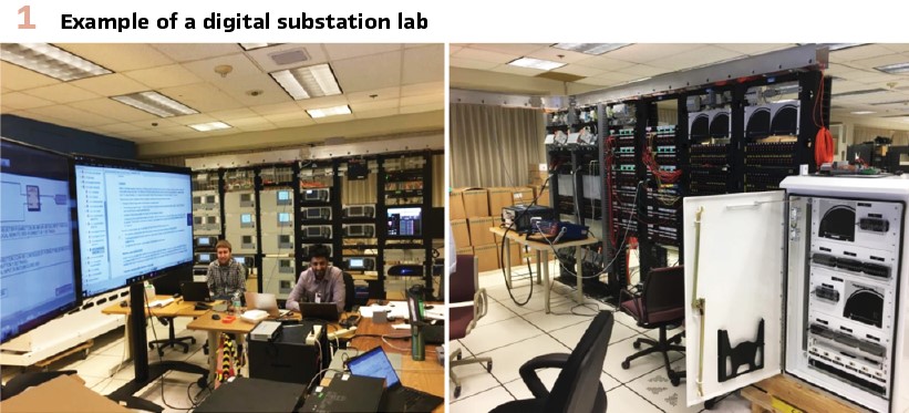
Many electric utilities have protection and control (P&C) labs that are used for testing and validation of new protection and control schemes with associated settings/configuration before the schemes are implemented in the field/substation. These labs use multiple sets of relay test sets that provide current and voltage signals to the equipment used in the P&C scheme under test. Trip control, close control and status for breakers / switches are often simulated by digital relay(s) or breaker simulator(s). Digital substations can be considered a new P&C scheme and treated similar to conventional P&C schemes with regards to the benefits of lab testing. This kind of testing is often called factory acceptance testing or FAT. Figure 1 shows an example digital substation lab. IEC 61850 testing tools can be used during lab testing to aid in validation of SV (sampled values) datasets, GOOSE (Generic Object Oriented) messages and communication links of the digital substation P&C scheme. The lab/FAT testing performs complete testing of the P&C scheme, including all protection element settings, logic, and configuration. The results of the lab/FAT testing for a particular digital substation P&C scheme are:
- Verification of configuration template(s) for MU cabinet(s)
- Verification of various relay/IED protection setting configuration templates
- Verification of protection and control logic within and amongst various relays/IEDs and MUs
- Verification of publisher and subscriber configuration of SV datasets and GOOSE messages of relay/IEDs and MUs
- Verification of Ethernet network switch configurations (such as VLANs and MAC address filtering)
Merging Unit – Factory Acceptance Tests
For new digital substation construction, the MUs or MU cabinet should be factory installed by substation equipment manufacturer (i.e., breaker manufacturer). A standard configuration should be loaded into the MUs that include generic/standard configuration of IOs, SV datasets and GOOSE messages that match the particular MU cabinet wiring design. Basic configuration testing/verification of MU cabinet should be performed at MU cabinet manufacturing site. Current/voltage/IO interface testing of a merging unit is similar to testing a conventional digital relay. The FAT will verify wiring to the merging unit is correct and generic/standard configuration of the merging unit is correct for particular P&C scheme for which MU will be implemented. This MU testing uses a traditional method of injecting currents and voltages to verify current/voltage analog measurements, verify digital inputs and output operation using standard relay testing tools. Similar to a conventional digital relay, the MU’s interface software can be used to verify current and voltage measurements and verify the states of digital inputs and digital outputs being tested.
Merging Unit – Site Acceptance Tests
Specific configuration of IOs, SV datasets, GOOSE messages and current/voltage settings of each MU for a particular P&C scheme should be uploaded at site during commissioning / site acceptance tests (SAT) using the MU’s interface software. SAT of each MU will verify specific configuration of the IOs, CT settings, PT settings, phase rotation, SV dataset(s) configuration and GOOSE messages configuration. Configuration of SV dataset(s) and GOOSE messages of each MU can be confirmed by using IEC 61850 testing tools from relay test manufacturer during commissioning / site acceptance tests (SAT) and as needed during maintenance/troubleshooting. MU’s interface software can monitor the status of the GOOSE inputs subscribed by MU and monitor the on-line/off-line GOOSE subscriber status of the subscribed GOOSE control blocks by particular MU being monitored. The MU’s interface software can be used to verify current and voltage measurements and verify the states of the digital inputs and digital outputs being tested. IEC 61850 testing tools can be used to read MU data, such as GOOSE states, measurements/SV data and GOOSE subscription status.
DS Protective Relay/IED Panel(s) – Factory Acceptance Tests
Panel assembly tests are reduced to a power up test on each relay/IED and verification of relay self-test alarm contact prior to shipping assembled panel. Factory acceptance testing of each relay/IED generic P&C configuration should be done in the lab testing described previously.
DS Protective Relay/IED Panel(s) – Site Acceptance Tests
The specific configuration for protection and control elements, SV datasets and GOOSE messages of each relay/IED for a particular digital substation P&C scheme should be uploaded at the relay panel manufacturer or at site during commissioning / site acceptance tests (SAT) using the relay/IED’s interface software. Factory acceptance testing of each relay/IED configuration template should be done in the lab testing described previously. SAT of each relay/IED will verify specific configuration of CT settings, PT settings, phase rotation, SV dataset(s) configuration and GOOSE messages configuration. The configuration of the SV subscription(s) and GOOSE messages publishing/subscription(s) of each relay/IED can be confirmed by using IEC 61850 testing tools from relay test manufacturer during commissioning / site acceptance tests (SAT) and as needed during maintenance/troubleshooting. The relay/IED’s interface software can be used to monitor the status of the GOOSE inputs subscribed by the relay/IED and monitor the on-line/off-line GOOSE subscriber status of the subscribed GOOSE control blocks by particular relay/IED being monitored. The relay/IED’s interface software should be used to verify the current and voltage measurements simulated by the IEC 61850 testing tools or directly from the various connected switchyard MUs.
Digital Substation System Testing/Verification
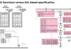
Commission testing of a substation verifies that the protection system is installed correctly, all the devices are operating correctly and that the devices are configured correctly for the application. Commissioning a digital substation is more efficient than commissioning a conventional substation because the testing can be done in parts or modules and IEC 61850 tools are available. MU cabinets and relay/IED panels can be commissioned separately. Most of the testing is already done as part of lab testing or factory acceptance tests (FAT) previously described which proved the particular digital substation protection and control scheme and have individually tested the main components of a digital substation such as MU cabinets and relay/IED panels. IEC 61850 testing tool can be configured to read MU or relay/IED data (GOOSE states, measurements/SV data, GOOSE/SV subscription status) and simulate SV/GOOSE data of MU and/or relay/IED on process bus / station bus Ethernet network. A general commissioning process for a digital substation is shown in Figure 2a.
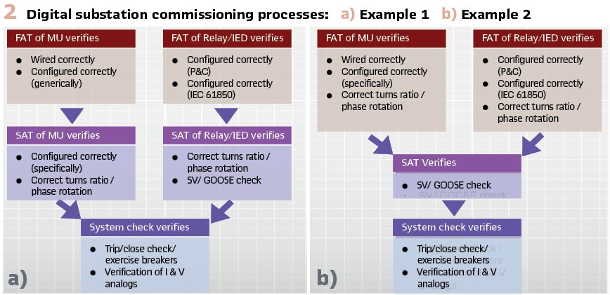
Using specific project MU configurations (if available) and specific project relay/IED configurations (if available) during factory acceptance tests (FAT) is best and will reduce site acceptance tests (SAT) as shown in the steps outlined in Figure 2b. Specific project settings/configuration of MUs and relay/IEDs, and specific communication (SV and GOOSE) mappings could be tested at FAT. This would reduce on-site work to fiber optic Ethernet cabling to primary equipment, confirmation of SV/GOOSE configuration/mapping using IEC 61850 testing tools (analysis of SCD file and network traffic) and final system checks. The described digital substation commissioning process can be modified or adjusted between new substations and the retrofit of existing substations.
DS Periodic / Maintenance Testing
Maintenance or in-service testing of a protection system proves PAC devices are still operating with defined performance parameters or when changes to device configuration or protection element settings are made. For a digital substation, only MUs may require regular maintenance testing. DS relay/IEDs are fully digital devices with complete self-monitoring and do not require maintenance / periodic testing. However, relay/IED may need maintenance testing if protection or control element settings are altered due to changing system conditions. Periodic testing of a digital substation verifies settings in the relays/IEDs have not changed, settings in the MUs have not changed, digital I/O of the MUs are operational, analog measurements of the MUs are within specifications, SV dataset(s) and GOOSE messages configuration have not changed using IEC 61850 testing tool and SV and GOOSE communication links have not changed using IEC 61850 testing tool.
Digital Substation Out-of-Service Maintenance Testing
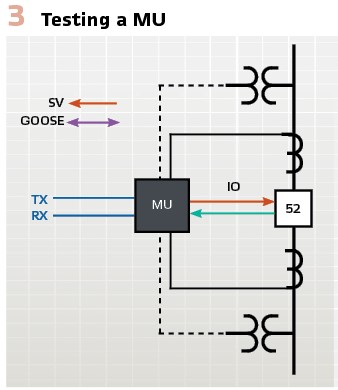
The MU is the digital to analog interface to the primary equipment and has the physical I/O for the protection and control system. This physical I/O should be tested at regular intervals to ensure MU is still operating correctly within desired performance parameters. Maintenance testing of a MU for either testing output contacts or analog inputs usually requires an equipment outage. This is to prevent undesirable operation during testing and to allow the exercise of circuit breaker(s) if desired. Three parts of MU shown in Figure 3 may require testing. The first is MU output contacts, which must be tested to ensure they operate and energize circuit breaker operating coils. The second is MU analog current and voltages inputs, where it is desirable to verify measurements are working correctly. The MU’s interface software can be used to verify current and voltage measurements and verify states of the digital inputs and digital outputs being tested. The third part is verification of configuration of IEC 61850 SV dataset(s) and GOOSE messages of each MU by using IEC 61850 testing tools from relay test manufacturer. The MU’s interface software can monitor the status of the GOOSE inputs subscribed by the MU and monitor on-line/off-line GOOSE subscriber status of subscribed GOOSE control blocks by particular MU being monitored.
Digital Substation In-Service Maintenance Testing
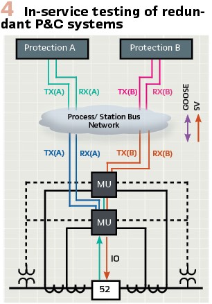
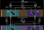
In most digital substations, there will be redundant relay/IEDs and redundant MUs used for protection and control of a particular transformer, transmission line, capacitor bank or bus (an example is shown in Figure 4). With redundant protection and control schemes, one of the P&C systems (relay/IED and associated MU) could be put into various IEC 61850 test modes for in-service maintenance testing such that each protection system could be tested while the one of the systems is still in service. Caution should be taken to isolate relay/IED or MU under test to avoid any accidental breaker trip or undesired exchange of IEC 61850 messages between IEDs due to the testing.
Edition 2 of IEC 61850 has two features that are available to accomplish isolation during testing, which are:
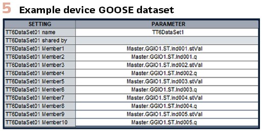
- Capability to put device/IED in test mode using IEC 61850 data object mode (Mod), such as LLN0.Mod. Based on Mod value of a logical device, the resulting test-mode status is determined by attribute behavior (Beh). IED manufacturers usually have a simple implementation with one Mod data object used to set entire IED in test mode. Some typical values for Mod data object (LLN0.Mod) are ON, TEST-BLOCKED and TEST. It is important that the quality of the data items of the GOOSE message, as shown in Figure 5, is configured in the device for IEC 61850 data object mode (Mod) to function properly:
- ON mode is for normal in-service operation. P&C functionality and I/O functionality of device are normal
- TEST-BLOCKED mode allows for device to be placed in a state where the device cannot negatively impact power system or other parts of substation automation system. This mode allows changing settings, loading new firmware, or changing communication connections. All IEC 61850 data published by device in TEST-BLOCKED mode will be test data and will be processed but not used by in-service devices in ON mode. All physical contact outputs of device are blocked when in TEST-BLOCKED mode. The test bit of the quality attribute of values sent via IEC 61850 services (SV and GOOSE) will be set to TRUE. The validity bit of the quality attribute of data sent via IEC 61850 services (SV and GOOSE) will be set to GOOD
- TEST mode ensures all IEC 61850 data published by the device will be test data and will be processed but not used by the in-service devices in ON mode. The test bit of the quality attribute of values sent via IEC 61850 services (SV and GOOSE) will be set to TRUE. The validity bit of the quality attribute of the data sent via IEC 61850 services (SV and GOOSE) will be set to GOOD
- Capability to use simulation flag (LPHD.Sim) in subscribing device for IEC 61850 GOOSE and IEC 61850 sampled values. IEC 61850 data object LPHD.Sim serves as a switch between the messages coming from the real IEC 61850 devices in system and simulated IEC 61850 messages coming from relay test sets or IEC 61850 testing tools. When device is in SIMULATION mode, received GOOSE messages and/or received SV data with “simulation” flag/bit set are used in place of the normal messages in subscribing device.
Merging Unit In-Service Tests
In-service tests of MU could be performed using IEC 61850 data object mode (LLN0.Mod). The steps for testing are:
1. Place MU into TEST mode. All IEC 61850 data published (i.e., SV data and GOOSE messages) by MU will be test data and will be processed but not used by in-service devices in ON mode
2. Perform contact I/O and I/V analog injection using relay test set and associated MU test switches to verify digital I/O of MU are operational and analog measurements of the MUs are within specifications. Caution should be taken to isolate MU I/O under test to avoid any accidental breaker operation. Verification of the configuration of IEC 61850 SV dataset(s) and GOOSE messages of MU can be performed by using IEC 61850 testing tools from relay test set manufacturer. MU could be left connected to process bus/station bus Ethernet network, since it is in IEC 61850 TEST mode, for IEC 61850 SV dataset(s) and GOOSE messages verifications by IEC 61850 testing tools
3. After testing is complete, place MU into ON mode for normal in-service operation and re-connect to equipment using associated MU test switches
Digital Substation Relay/IED In-Service Tests
In-service tests of relay/IED could be performed using IEC 61850 data object mode (LLN0.Mod) and simulation flag (LPHD.Sim). The steps for testing are:
1. Place relay/IED to be tested into TEST mode. All IEC 61850 data published (i.e., GOOSE messages) by relay/IED in TEST mode will be test data and will be processed but not used by in-service devices in ON mode
2. Place relay/IED under test into SIMULATION mode so it will accept simulated SV and simulated GOOSE messages. A relay/IED in SIMULATION mode will use live process data for every subscribed SV dataset and subscribed GOOSE message until it receives simulated SV or GOOSE data (a message where the simulation bit is TRUE) for a specific message. Note the relay/IED under test is now in both TEST and SIMULATION mode
3. Testing requires controlled data, so it is necessary to turn off all live process data by simulating all SV and GOOSE messages to relay/IED under test. Depending on the IEC 61850 test tool used, this may require simulating SV and GOOSE messages one at a time to turn them all off, or this could be done in batches of SV and GOOSE messages. Testing is then performed by having IEC 61850 testing tool simulate fault events, publishing simulated SV and simulated GOOSE messages, and verifying the protection element settings of the relay/IED under test
4. Once testing is complete, the following steps should be followed to place device into normal operation:
a. Relay/IED under test is taken out of SIMULATION mode to only use live received GOOSE messages and live received SV data
b. Relay/IED under test is returned to normal in-service operation by placing to ON mode
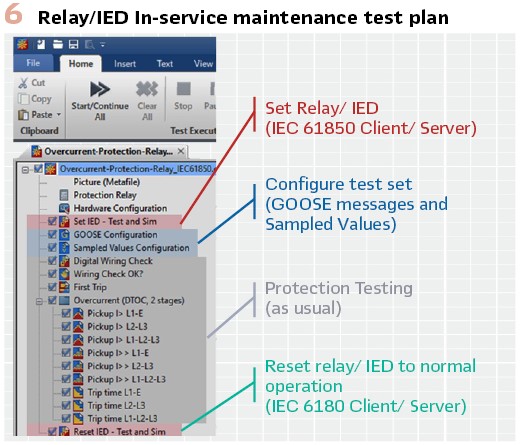
An example automated test plan for in-service testing of relay/IED is shown in Figure 6.
Digital Substation Troubleshooting Tools and Methods
Within IEC 61850, LGOS (logical node for GOOSE subscription) can be used for monitoring the status of GOOSE subscriptions in a device. Similarly, LSVS (logical node for sampled values subscription) can be used to monitor the status of SV subscriptions in a device. A recommended commissioning and maintenance method for the digital substation is the use of HMI screens on relay/IED, substation gateway/HMI, or IEC 61850 testing/monitoring tools to show the on-line connection status of the following using LGOS and LSVS statuses:
- Relay/IED:
- On-line status of connected sampled value(s) from MU(s)
- On-line status of subscribed MUs publishing GOOSE messages
- On-line status of subscribed relays/devices publishing GOOSE messages
- Merging Units (MUs):
- On-line status of subscribed relays/devices or MUs publishing GOOSE messages
With the above information readily available, the P&C technician can easily determine which device is off-line and take appropriate action. There are several possible reasons for a commissioned relay/IED to show an off-line status for a subscribed SV dataset or GOOSE messages from a particular MU:
- Publishing device (i.e., MU) is not powered up
- Ethernet network switch issue
- Fiber optic cable / connector issue
- Publishing MU configuration (SV and GOOSE) has changed
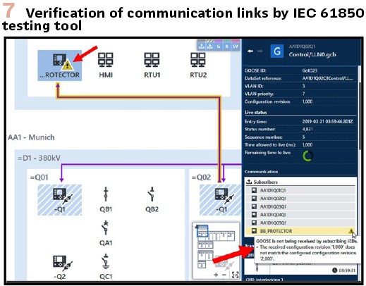
IEC 61850 testing tools are available to aid in all stages of digital substation implementation and operation, such as design, lab testing, factory acceptance tests, site acceptance tests, commissioning, and maintenance. IEC 61850 testing tools uses System Configuration Description (SCD) file for digital substation P&C scheme, which contains all IED configurations (SV and GOOSE) and communication configuration between relay/IEDs and MUs. After importing SCD file into IEC 61850 testing tool, the entire digital substation scheme can be visualized similar to a single line diagram or HMI. IEC 61850 testing tools can perform the following:
- Verification of SV and GOOSE communication links (example shown in Figure 7)
- SV Dataset Simulation
- Simulation/Publishing of GOOSE messages
- Simulation of Relay/IED MMS server functionality
Conclusions
Advantages of digital substation P&C system include faster implementation with fewer errors, a more reliable and repeatable final product, and significant cost savings from efficiencies in design, testing/commissioning, maintenance and operation. Efficient implementation of testing processes of a digital substation is achieved by lab testing, factory acceptance tests, site acceptance tests and system checks. Maintenance testing can be performed by placing the device/IED in test mode or test and simulation modes. IEC 61850 testing tools and the use of LGOS and LSVS aid in testing and troubleshooting a digital substation P&C scheme.
Biographies:

Craig Wester is a Senior Technical Application Engineer for the protection and control division of GE Vernova for the South Region of North America. He was previously a Senior Regional Sales Manager for the south region of GE in North America for protection and control. He joined GE in 1989 as a Transmission & Distribution Application Engineer. He received his Bachelor of Science in electrical engineering from University of Wisconsin-Madison. He is a senior member of IEEE.

Ravindranauth Ramlachan (Mike) is Application Team Leader for the protection and control division of GE Vernova for the South Region in North America. He was previously a Lead Sales Application Engineer at GE in North America for protection and control. Prior to joining Alstom/GE in 2013, he worked at Consolidated Edison of NYC in various P&C positions. He has a Master of Science degree in electrical engineering acquired from Stevens Institute of Technology.

Eugenio Carvalheira received his BSc in Electrical Engineering and his MSc in Computational Engineering. He started his career as a Project Engineer designing, implementing, and commissioning power grid Protection, Automation and Control systems. He joined OMICRON in 2018 as an Application Engineer and became Engineering Manager for North America. Eugenio cultivates a special interest for digital substations, having published many articles and papers, and hosted workshops on this topic. He is currently Global Business Development Manager for OMICRON’s Power Utility Communication solutions, based in Houston, TX. He is also an active member of IEEE PSRC and PSCC working groups.


