by Andre Smit, Siemens Industry, Inc., USA, Eric Easton and Kevin Bryant, CenterPoint Energy, USA
The article contains the work performed at CenterPoint Energy to find a solution to a substation vulnerability that is very old but now becoming more and more of an issue with lawmakers in various countries. In the United States, a Presidential Executive Order on Coordinating National Resilience to Electromagnetic Pulses was signed on March 26, 2019 directing federal agencies to coordinate in assessing, planning and guarding against the risks from human and natural electromagnetic pulse (EMP) sources.
One human way an EMP can be produced is if a nuclear device is detonated in the upper atmosphere. The pulse produced by the detonation is a powerful electromagnetic field covering an unusually large area that can span hundreds or even thousands of miles. Among the most severe threats confronting modern societies, an EMP attack is an example of a malicious hazard that could cause a classic Black Sky-class catastrophe. An EMP strike could cause a large-scale blackout associated with widely distributed damage of a portion of the digital protection and control devices installed in substations throughout the grid. Another potential human-made EMP source comes from portable Intentional Electromagnetic Interference (IMEI) devices that can also produce an electromagnetic pulse strong enough to damage the protection devices in a substation.
It was decided by CenterPoint Energy Leadership to take an active role and find a solution. In 2015 a backup control center building was constructed by the company’s electric utility to the military EMP standard MIL-STD-188-125. The focus has since been moved to substations to further bolster EMP resiliency in a systemic manner.
This article will describe a resilient Protection and Control system design that CenterPoint developed while investigating EMP from 2015 to 2019.
There are several approaches that can be taken to make a substation protection and control house resilient to both nuclear detonated EMP and portable IEMI attacks. However, these approaches are extremely costly, and cost is the major challenge for electric utilities to address. Existing solutions to EMP threats are estimated to cost over $2M per substation.
When attempting to mitigate the effects of high-power, high-frequency electromagnetic energy, the smallest details can compromise efforts to achieve the needed levels of shielding effectiveness (SE). When using the correct components, the digital substation is uniquely capable of achieving electromagnetic resiliency against the harshest High-Altitude Electromagnetic Pulse (HEMP) and IEMI environments.
Electromagnetic Mitigation
The HEMP environment has been studied since the early 1960s when both United States and Russian scientists noted the phenomenon of electric fields capable of damaging electronics emanating from a nuclear burst at altitudes exceeding 19 miles. The resulting 1 GHz HEMP is capable of 50kV/m which can couple to power conductors and control cables. Significant portions of the coupled energy may be reflected though instrument transformers to secondary control cables as conducted energy. Radiated energy can directly couple to unshielded control cables and devices compounding the effects of conducted energy. Combined, the radiated and coupled energy can result in failures of protective relays and SCADA RTUs in the substation environment.
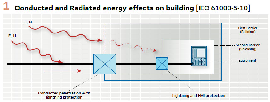
Conducted and Radiated energy effects on building [IEC 61000-5-10]: The effects of such an event are experienced by space and ground-based assets within a line of site from the burst. (Figure 1). The most commonly cited methods of mitigation can be found in MIL-188-125, the United States Military Standard for Hardening of Fixed Installations Against HEMP. However, many of the provisions listed in the standard are difficult to employ in a power substation and require new construction as opposed to retrofit applications. Recent empirical testing and modeling by the Electric Power Research Institute (EPRI), concluded that a HEMP event would result in interconnection level disruptions and most likely system collapse. The Electromagnetic Defense Task Force (EDTF) however, reviewed the EPRI report and suggested that the system damage may be much more severe. Therefore, study continues and efforts to identify effective HEMP mitigation methods have increased significantly.
Alternately, an EMP attack from a portable IEMI would be a more localized event. These devices could range from the size of a suitcase to the bed of a standard size pick-up truck. While the energy level is lower than that produced from a HEMP, the frequency range may extend to 10 GHz. The increased frequency enhances coupling for shorter antenna. The enhanced coupling increases the capability of an IEMI device to disrupt electronic data transmissions such as SCADA telemetry. Operators may be misled into taking incorrect actions as a result of faulty data.
The fundamental aspects of comprehensive EMP mitigation include more robust SE for electric grid components, device power filtering, conducted energy surge suppression and high-frequency bonding and grounding. Each of the aforementioned aspects must be accomplished to achieve systemic protection. Undoubtably, technologies exist to accomplish the stated objectives using legacy substation designs; however, they were found to be cost prohibitive, require lengthy construction processes and necessitate new construction as opposed to retrofit.
The desired solution needed to be economical, compact, low maintenance and allow flexible protection and control configurations. By combining proven electromagnetic mitigation techniques and Digital Substation Design technology, CenterPoint Energy has developed a CenterPoint Energy’s cost-effective EMP mitigation solution which exceeds military standards. The basis of CenterPoint Energy’s cost effective EMP mitigation solution is a module designed using the digital substation architecture. The two fundamental aspects of radiated and coupled energy are inherent to a Digital Substation design.
The physically compact design greatly reduces cost and fiber optic cables decouple primary gear from the protection and control system. More precisely, the resulting solution increases typical shielding effectiveness from 30 dB to greater than 100 dB at one-fifth the costs of the Non-Digital Substation Designs.
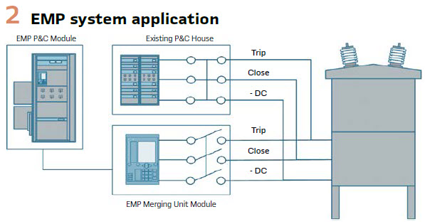
The EMP Mitigation unit or module designed by CenterPoint Energy is intended to serve as indicated in Figure 2 as an online non-tripping data collection and resiliency device. Pre-EMP the device can be used to collect operational data and serve as reference to non-hardened systems in the event of an attempted IEMI attack. In such a scenario, the values from the hardened and un-hardened systems would be compared to determine if data corruption had occurred. Response to an EMP event would entail enabling tripping functions in the hardened system to allow operation of the substation to resume should the EMP damage traditional relaying.
CenterPoint Energy ultimately selected Siemens SIPROTEC 5 hardware for the EMP Mitigation unit due to its ability to support the design requirements of compactness and low maintenance, as well as flexible protection and control functionality.
Compactness
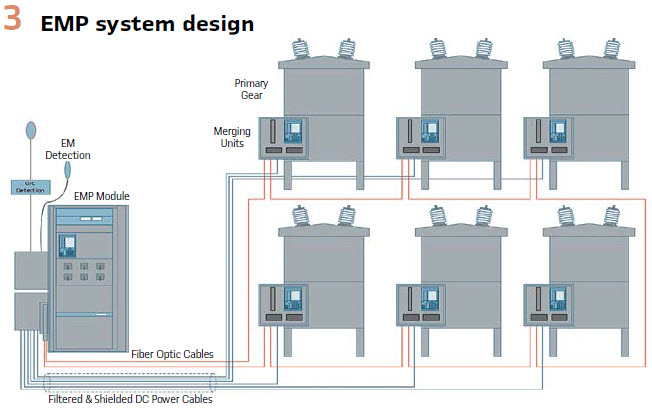
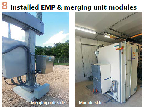
The use of fiber optic cables as indicated in “EMP System Design” eliminates many of the space related and coupled energy concerns associated with large numbers of analog and control terminations required for traditional relay panels. It must be understood that the metallic CT, VT and control cables typically landed from the substation yard to the relay terminals act as long antennas that will capture and transmit the damaging coupled energy to the protection relays. These connections are now located at merging units within the circuit breaker in the substation yard and use very short connection runs. The merging units serve as analog to digital converters to transmit current and voltage values to relays in the control house.
An added benefit to current and voltage terminations remaining in the substation yard is safety and a reduction in construction outage duration. Once the merging unit is installed in the substation yard, construction can continue with the breaker back in service. The ability to protect a transformer and multiple feeders with a single relay also aids the compactness of the solution. The reduction in the number of relays allows the use of a single 36”WX42”DX78”H enclosure to replace 16 traditional relay panels typical in many substation designs. (Figure 3).
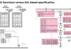
EMP System Functions
A full suite of substation protection functions are available in the Central Protection module. Protection functions can be assigned within and between Central Protection modules. Space available in the cabinet of the CenterPoint Energy-designed EMP Mitigation unit to support multiple Central Protection modules in order to support both distribution substation and complex transmission substation applications. The Central Protection Modules are connected via fiber optic cables to Merging Units. This point to multipoint architecture is extremely modular, flexible and adaptable to the substation design for green or brownfield installations.
Functions include:
- EMP Protection against radiated and coupled energy
- Provide substation operational and nonoperational data and maintain NERC-CIP
- Communication and Controls
- EM Detection and Alert
- GIC Detection
- Substation Protection Functions
- Shielded and Filtered DC Power to Merging Units
- Pilot Scheme Communications
The EMP Module will support up to 96 Analog steams, current and voltage, from merging units deployed at the substation breakers and transformers.
In order to complete the design, mitigations for radiated and coupled electromagnetic energy were developed for the EMP modules. These include:
- Effective device shielding
- Control cable shielding
- Device power filtering
- Conducted energy surge suppression
- High-frequency bonding and grounding
System Design
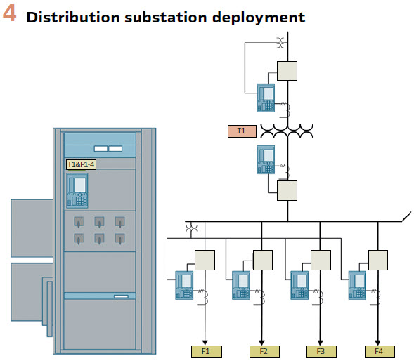
CenterPoint Energy decided to deploy the first EMP Mitigation module in a distribution substation. The substation configuration is depicted in Figure 4.
The system is for a single transformer and 4 feeder application consisting of the Central EMP module and 6 merging units. The EMP Digital system provides protection functionality for the same zones of protection as the standard non-EMP protection and control system.
The EMP Mitigation module includes the Central Protection Module connected via fiber optic cables to the merging units located in the substation yard. The EMP module houses an RTU, Ethernet Switches, Synchronizing Equipment, Cooling Fan, DC UPS and a DC to DC convertor. The RTU is connected via fiber to the substation Telecom cabinet. Provision was made in the cabinet design to house Pilot Wire Communication equipment when deployed in a transmission substation. A hardened PC is included in the module that has the relay and merging units programming and analysis software installed. The entire digital substation IEC 61850 project is saved on this PC. This ensure retention of all settings and data with compatible firmware and software versions. The EMP module will provide immediate and complete availability after an EMP event to operations and engineering staff. It is likely many engineering PC’s in possession of engineers and technicians could be damaged during an EMP event.
On the first EMP Mitigation module deployment, breaker control switches were provided for the associated breakers. The control switches are merely wired to the Central Protection Relay that execute the control commands. It is envisaged to not provide control switches on future systems. Control will be done through the Central Protection Relay HMI.
The existing protection and control logic were duplicated in the digital substation design. The protection settings were also applied to all protection functions in the central protection relay to reflect the existing system’s settings. In the first installation 3 central protection devices were installed to prove system’s expansion capability.
The Central EMP module is supplied with 125V DC from the station service. The supply power passes through an EMP/HEMP filter and then to a UPS. EMP/HEMP power line filters provide over-voltage and Electro Magnetic Interference (EMI) and Radio Frequency Interference (RFI) protection.
The UPS output is at 48V DC and supply all the communication and other ancillary devices in the Central EMP module.
The 48V DC output from the UPS is also connected to the DC to DC convertor. This convertor provides a 125V DC output supply. The 125V DC provide power to the Central Protection Module and merging units.
The merging units 125V DC supply is first passed through a HEMP filter and then through a bonding and grounding cable management system and connected through shielded cables to each merging unit. At the merging units the cable passes again through a bonding and grounding cable management system to enter the merging unit cabinet.
The two binary inputs on the merging units are connected to the relevant breaker’s status contacts. Two output contacts for trip and close are connected to open tests switch contacts. From the test switches the trip, close and DC voltage is connected to the breaker trip and close circuits.
As indicated in Figure 2, in the normal condition the test switches will be open to allow the existing protection and control system to operate if the protection system is unavailable.
Communication of Digital Substation
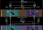
The first CenterPoint Energy deployment at a distribution substation is described in this article. The merging units used were the first generation from Siemens and did not include all the functionalities and features as envisaged in future deployments. The communication architecture will drastically differ in future deployments. The Central Protection Relays and Remote Merging Units will support various architectures that best support the substation design. (Figure 5).
The Central Protection Relay is connected to the merging units through an HSR ring. This network provides the Central Protection unit with Sampled Measured Value streams from all the merging units. In the Central protection relay the protection and control functions are assigned to the available voltages and currents and circuit breakers. GOOSE messages are used to transmit status, trip and close commands between the merging units and the central protection relay.
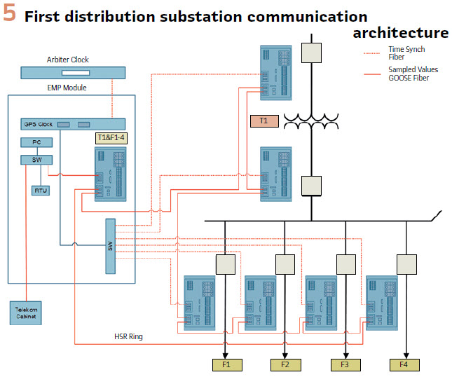
Time synchronization is achieved using the existing Arbiter Master Clock in the substation. A fiber optic connection was formed using necessary IRIG-B TTL to Fiber optic transceivers between the Arbiter Clock and the Precision Timing Clock mounted in the EMP module. The precision timing clock is connected though TTL/Optical converters via fiberoptic cables to the Merging units. IRIG-B is used for time synchronization. Future deployments will likely be PTP and negate the separate Time Synch network.
The Central Protection relay is connected through an Ethernet switch to an RTU and compact industrial PC.
The final communication architectures for transmission substations will differ from the distribution substation design. The protection relay and merging units support both HSR and PRP redundancy, providing the system with the flexibility to be deployed in the most efficient and cost-effective manner.
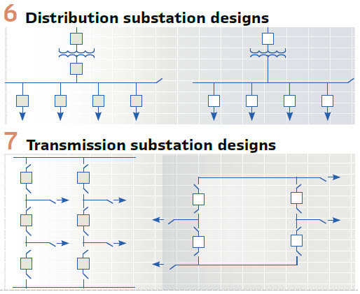
CenterPoint Energy has several standard substation designs that include the following topologies which the EMP Mitigation module must support.
- Distribution Substation designs include two standards with or without low side transformer breakers. The EMP module must support applications of 1 to 4 Transformers and 4 to 16 Feeders. (Figure 6).
- Transmission Substation designs include Breaker and a Half with 1 to 6 bays and Ring Bus Arrangements. (Figure 7).
System Construction Deployment
The EMP system deployment executed at the first substation was a crucial factor in the success of the system.
The aim was to deploy the system with little or no impact to the availability of the substation. The Central EMP module was installed in the existing control house. Merging Units were installed at the breaker and transformer locations.
Breakers could be taken out of service one at a time to perform the required wiring integration. There was as a result, limited impact to the normal substation operation and availability through construction and commissioning.
Fiber optic cables were installed from the EMP module to the merging unit locations. The 125V DC supply cables were also installed between the EMP module and the merging units.
The system testing and commissioning was then performed while the existing protection and control remained in service.
The entire project construction and deployment took 4 weeks. This proved to CenterPoint the viability of the system in that it can be deployed rapidly and cost-effectively with minimal disruption to normal operations.
A lesson learned during the deployment is to improve the system functionality to better support testing. Testing required one person at the central protection device and one person injecting secondary currents and voltages into the merging units. CenterPoint believes this process should be improved to make system testing easier by not requiring two persons to perform testing.
Additional Benefits
The EMP Digital Substation protection system can be monitored and compared to operations of the existing protection system. Several operations have already occurred at the substation and could be compared with the existing protection system operations.
The valuable Non-Operational Data available from the system can be retrieved remotely from the EMP system without compromising NERC-CIP as the merging units are not physically connected to trip and control the circuit breakers. (see Figure 8).
Maintenance
By minimizing the footprint of the EMP protected enclosure, maintenance tasks are greatly reduced. Larger facilities require annual testing to verify shielding effectiveness has not degraded. Risks of the shield accidentally being compromised with larger protected zones were also considered. Additionally, provisions for building mechanicals (A/C and Water) are not required for the module concept. Maintenance is limited to the cleaning of the doors and wave guide vents. The wave guides require periodic removal of dust. While the doors require the cleaning of contacts twice a year using a light abrasive pad and denatured alcohol. Provisions are being made to incorporate differential noise measurements to perform continuous real-time shielding effectiveness tests.
Conclusion: The CenterPoint Energy EMP mitigation solution is cost effective compared to building a new control house. In our estimates, a new EMP control house with protection and control equipment will cost around $2 million to $2.5 million. The EMP module enclosure system would be less than 25% of the cost of a new EMP control house of equivalent SE.
In conclusion, we believe using the EMP Mitigation module designed by CenterPoint Energy would be a cost-effective retrofit solution to harden our substations for an EMP attack. By being a redundant system, we also will have a backup system in case of fire or flooding control house emergencies, and it does not intrude on our current protection and control system. This project is proof that the Digital Substation is a very cost-effective high resiliency solution that can be utilized for multiple recovery scenarios. A digital substation design concept provides an extremely compact solution with many benefits especially rapid deployment in the event of catastrophic man made or natural disaster.
Biographies
Andre Smit completed his studies at the Vaal University of Technology in Power Engineering in South Africa in 1988. He joined Siemens in 1989, working in the field of protective relaying for the past 31 years. He specialized in generator protection systems. From 2004 to 2008 Managed the USA Siemens Protective relay business unit. Current position is P&C Product Manager for Protection and Automation including Distribution Feeder Automation systems. He is the principal inventor of a new Distribution Automation System and holds various patents on new methods to protect and automate distribution feeders. Andre Smit is a member of the IEEE.
Kevin Bryant has been working in the field of protective relaying for over 13 years including 5 years as a Supervising Engineer in Relay and SCADA group at CenterPoint Energy. His current position is Substation Electrical & Structural Manager at CenterPoint Energy. Kevin completed his studies at Tulane University in Electrical Engineering in New Orleans, LA and is a registered Professional Engineer in the state of Texas.