by Walter Schossig, Germany, and Thomas Schossig, OMICRON electronics GmbH, Austria
With the introduction of digital protection several new possibilities and tasks for the protection engineers and testers came up. As examples:
- Choosing the proper protection type and vendor
- Checking the delivered device
- Creating the default parameter set for the different types of feeders
- Preparing the documentation of the parameters
- Commissioning tests
- Creating the time grading
- Defining the detailed parameters of the relay
- Checking defined parameters in the relay
- Regularly and maintenance testing
- Documenting the test results
- …
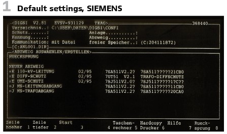
Figure 1 shows the default parameter settings for 110 kV line-, differential- , overcurrent-protection.
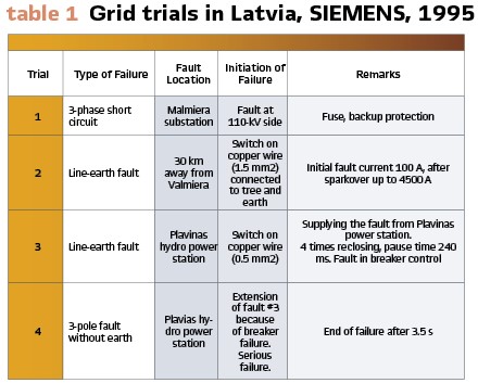
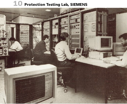
SIEMENS performed a lot of tests with new digital relays- in the early 1990s in Eastern Europe (Ukraine, Poland, Russia, Czech Republic, Latvia, and Romania). The new distance relay 7SA513 could be tested in Lithuanian 330-kV- grid, as a part of the new interconnected grid of the Baltics (Latvia, Lithuania, and Estonia with load dispatching center in Riga). It was in November of 1995, when the tests of the line protection оof substation Valmiera and hydro power station Plavinas took place. The main topics of interest were:
- Checking the accuracy of short circuit calculations, calculating the dynamic and static stability and choosing the protection settings
- Checking the reliability of 7SA513 under different grid conditions
- Checking the accuracy of the fault locator
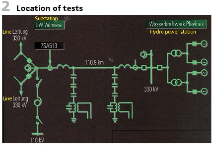
- Table 1 delivers an overview of all tests.
Figure 2 shows the setup under test. Figure 3 shows the fault with the tree, just before the arc was there.
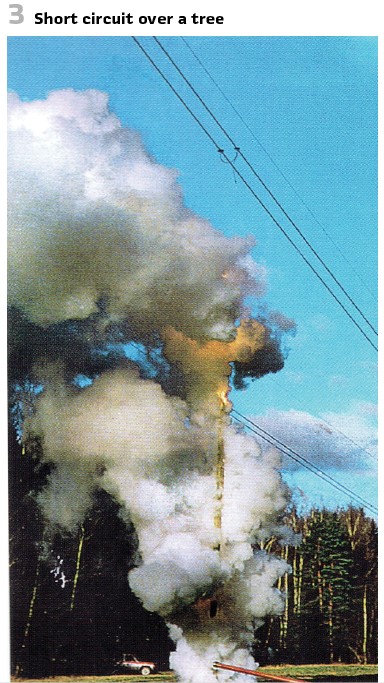
It was important to simulate faults with high transmission power. The angle between the driving voltages at both ends of the line was close to the stability limit. As described in the table the short circuits were initiated as in the practice. With the conductor cross-section chosen the burn-through took some time. So, the resistance of the tree limited the current for some time. After the first arc the fault current was only between 60A and 100 A. It took 20s to develop a full short circuit.
After the sparkover the fault was 2700 A, after 100 ms even 4500 A. Faults like this were very common during the summertime with high temperatures.
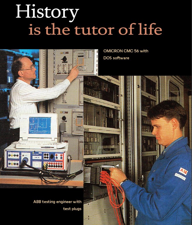
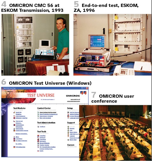
OMICRON was mentioned already in part 1 of the article. The first CMC 56 was delivered to South Africa in November 1993 (Figure 4). The first GPS-synchronized End-to-End tests with CMC 156 were performed in South Africa in March 1996 (Figure 5).

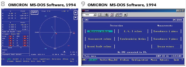
OMICRON replaced the DOS software (Figure 8 and 9) in 1998 with Windows software. OCC (Omicron Control Center) in Test Universe is shown in a later release in Figure 6.
OMICRON is hosting very successful German user conferences (“Anwendertagung”) since the 1990s. The concept of the conference was to share experiences and latest developments (Figure 7).
An example of the wide range of topics at such a user meeting in 1998 in Düsseldorf are some papers:
- Braun: Creation of test plans and test reports in OMICRON Control Center
- Kuntner: Application examples for Quick CMC
- Wurzer: Concept and Application of State Sequencers for testing generator protection
- Steger: Field trials in the 100-kV grid of the Isar-Amperwerke with OMICRON GPS receivers
- Wagner: Grunert: Commissioning of a new protection system in the 400 kV substation Friedrichshain of BEWAG with OMCRON Test Universe. Technology, Application and Documentation
- Stolle: Neunstöcklin; Losing; Wurzer: Application of OMICRON Testing Devices during the commissioning of decoupling protection in the 100-kV- grid of NASF Ludwigshafen
- Zollmer: Testing of multifunctional relays with CMC 56 and OMICRON Test Universe.
The RIO format (Relay Interface by OMICRON) offered the possibility to setup to test software.
The development of software over the years shall be covered in a later article.
Another development in the 1990s were focusing on digital grid simulators and EMTPs (Electromagnetic Transients Program).
In 1994 SIEMENS published a paper on the application of digital simulation with NETOMAC and EMTP with 7SA513 numerical high voltage protection.
Figure 10 shows the simulator for the protection development of 7SA513 with AC-DC-Simulator.
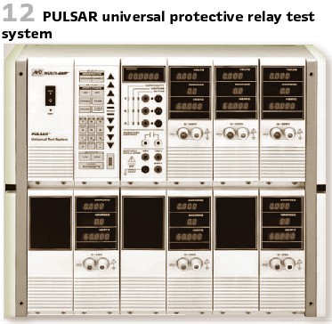
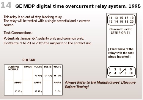
Digital transmission of measuring values utilizing fiber wires could be used for current comparison protection as SIEMENS 7SD51. The efforts for commissioning and maintenance could be reduced dramatically. The PULSAR Universal Test System by AVO Multi-Amp Corporation was introduced in 1993 (Figure 12).
The device came with test sheets describing the test of typical relays to perform acceptance tests. Figure 14 shows an example with GE relay.
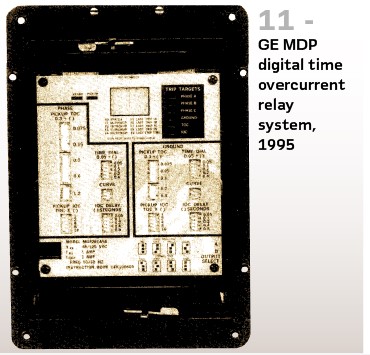
GE released the MDP Digital Time Overcurrent Relaying System for Protection and Control in 1995 (Figure 11).
Type MDP relays were digital, microprocessor based, non-directional overcurrent relays, that protect against phase-to-phase and phase-to-ground faults.
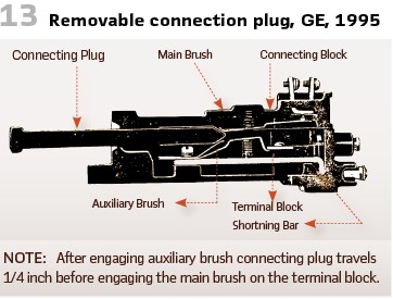
The program operation was a MS-DOS tool, utilizing hot keys and shortcuts. Periodic tests and routine maintenance were essential parts of the system. The manual contained a chapter on acceptance testing and recommended applying this for routine testing of the settings. A connection system was developed (Figure 13).
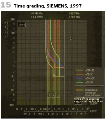
On the one hand, the PC became a common tool for protection engineers. SIEMENS presented the program CUSS (Computer unterstützte Schutzstaffelung – Computer aided time grading) in 1997. (Figure 15).
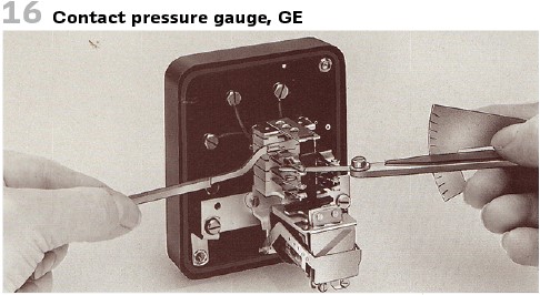
On the other hand, the screwdriver was still in the 1990s a recommended tool, as well as the contact pressure gauge (Figure 16).
The testing recommendations for digital protection relays with self-supervision were released in April 1995. In 1998 a document with additional recommendations for utilizing digital substation automation in distribution systems (“Erganzende Empfehlungen zur Anwendung Digitaler Stationsleittechnik in Verteilnetzstationen”) described the application of the protocol IEC 60870-5-103 for combined protection and control in bay controllers.
Also, other vendors tried to cover the testing aspects within their product portfolio. AEG presented a testing approach utilizing ATP for grid simulation and automated testing in 1995.
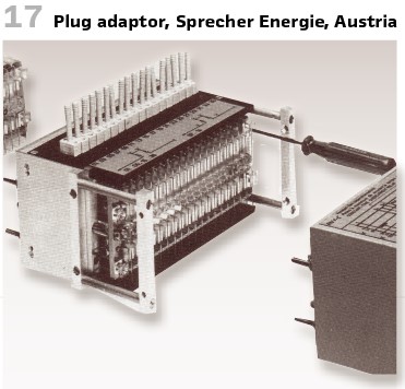
Sprecher Energie from Austria offered test devices and equipment. (Figure 17).
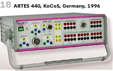
MS Windows became the state of the art for PC operating systems. The first vendor of protection test sets releasing a PC software was KOCOS (Germany) in 1996 for the ARTES 440. Also, the relay software was released for MS Windows (Figure 18).
There have been also activities to automate protective relay testing. The Spanish utility Iberdrola S.A. and the University of the Basque Country have been developing tools to automate protective relay testing, analyze the location and characteristic of faults in the network on the basis of oscillographic records, and to simulate real or hypothetical fault conditions on a protective relay in order to monitor its behavior. The testing system consisted of protection verification automatic system (SVAP) which was a steady-state testing system that helped carry out relay reception, commissioning, and preventive maintenance tasks.
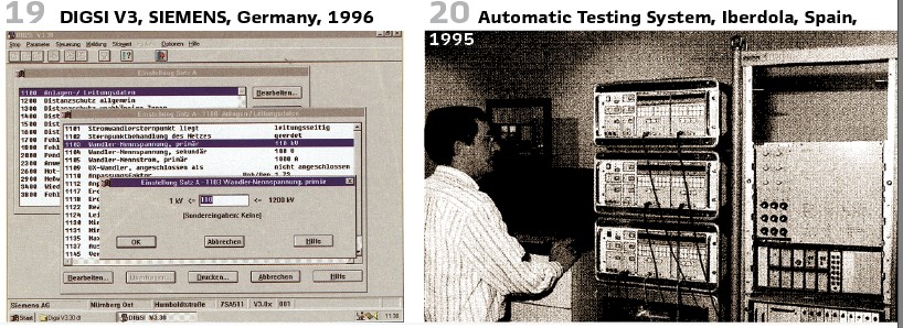
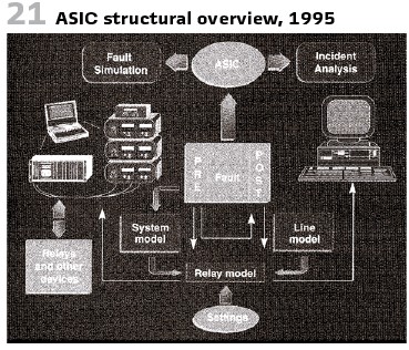
The system also contained a short circuit integrated analysis and simulation (ASIC), which evaluated the performance of a relay installed at a position of the system and dynamically simulates real or calculated faults on it (Figure 21).
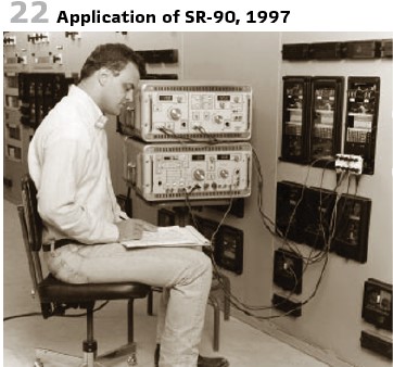
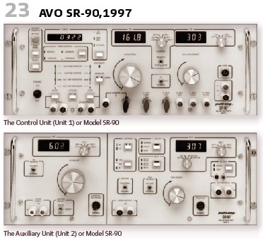
AVO International released Universal Protective Relay Test Set “Multi-Amp Model SR-90” (Figures 22, 23).
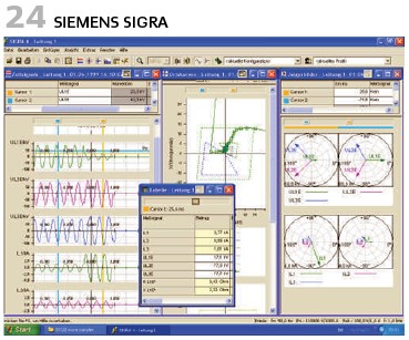
SIEMENS presented with the digital distance protection 7SS52 (SIPROTEC 4) the new software DIGSI 4 for V4 devices in 1998. SIEMENS Sigra allowed the visualization and analysis of fault records and COMTRADE files (Figure 24).
At the end of the decade, in August 1999, Kingsine Electric in China released the relay test set model 308C+, the first generation of microprocessor-based Protection Relay Test Set in China.
info@walter-schossig.de www.walter-schossig.de
thomas.schossig@omicronenergy.com
Biographies:

Walter Schossig (VDE) was born in Arnsdorf (now Czech Republic) in 1941. He studied electrical engineering in Zittau (Germany) and joined a utility in the former Eastern Germany. After the German reunion the utility was renamed as TEAG, Thueringer Energie AG in Erfurt. There he received his master’s degree and worked as a protection engineer until his retirement. He was a member of many study groups and associations. He is an active member of the working group “Medium Voltage Relaying” at the German VDE. He is the author of several papers, guidelines and the book “Netzschutztechnik
[Power System Protection]”. He works on a chronicle about the history of electricity supply, with emphasis on protection and control.
Thomas Schossig (IEEE) received his master’s degree in electrical engineering at the Technical University of Ilmenau (Germany) in 1998. He worked as a project engineer for control systems and as a team leader for protective relaying at VA TECH SAT in Germany from 1998 until 2005.
In 2006 he joined OMICRON as a product manager for substation communication products. He is author of several papers and a member of standardization WGs.